Gate Motors Blank Guide

13_2008
PRODOTTI
PRODUITS
PRODUCTS
ERZEUGNIS
PRODUCTOS
Manuale d’Installazione e d’Uso
Manuel d'Installation et Utilisation
Installation and use manual
Handbuch der Installation und des Gebrauchs
Manual de Uso e Instalación
AUTOMAZIONI PER CANCELLI A BATTENTE
AUTOMATISMES POUR PORTAILS A BATTANTS
AUTOMATION FOR SWING GATES
AUTOMATISIERUNG FÜR FLÜGELTORE
AUTOMATISMOS PARA BATIENTES

SCHEMA FUNZIONALE - SCHÉMA DE FONCTIONNEMENT
OPERATIONAL DIAGRAM - FUNKTIONSPLAIN - ESQUEMA FUNCIONAL
160
320
380
65
24V 230V OIL
24V dc
0,8 - 1
60 W
-------
230V ~ 50 Hz
1,2 - 1,7
300 W
10 µF
230V ~ 50 Hz
1,2 - 1,7
300 W
10 µF
200 N
66
1400 g/m
2,50 m 3,00 m 3,00 m
200 Kg 300 Kg 300 Kg
110° 110° 110°
15” 15” 15”
90% 50% 60%
300 N
66
1400 g/m
300 N
66
1400 g/m
-------- 150° 150°
-25° - +70°C -25° - +70°C -25° - +70°C
mt= Lunghezza anta
Longueur du portail
Leaf lenght
Torflügelbreite
Dimensiones hojas
Kg= Peso anta
Poids du portail
Leaf weight
Torflügelgewicht
Pesa de la hoja
Kg
mt
2,5 3,0 3,5
200
300
400
500
600
_
_
_
_
_
_
_
_
_
Il diagramma è valido con tutta elettronica PROTECO
Ce diagramme n’ast valable que pour une installation avec une électronique PROTECO
The diagram is efective with the whole of PROTECO electronics
Das diagramm ist gültig mit PROTECO elektronic
El diagrama es válido si se utiliza electrónica PROTECO
1 Motoriduttore-
2 Centraleelettronica-
3
4
5
6
7
Motoreducteur-Gearmotor-Antrieb- Motorreductor
Centraleélectronique-Electroniccontrolunit-Elektroschrank-Centraleléctronica
Fotocellule - Photocellules - Photocells - Fotozelle - Fotocélulas Rx
Tx
Antenna-Antenne-Aerial-Antenne-Antena
Ricevitoreradio-Récepteurradio-RadioReceiver-Funkempfänger-Receptorradio
Lampeggiatore-Clignotant-Warninglight-Blinkleuchte-LuzIntermitente
Selettoreachiave-Contacteuraclé-Keycontactor- SchlüsselschalterSelectordellave
--
A 3 x 1,5+T
B 2 x 1,75+T
F 2 x 0,75
C 2 x 0,75
2 x 0,75
_
C¹ 4 x 0,75
D
6
3
3
3
1
1
2
AA
F
D
C¹
C¹ C
C
7
3
5
4
Alimentazione - Alimentation - Power supply - Anschluss - Alimentaci n
Assorbimento - Consommation - Absorption - Stromaufnahme - Absorción de línea
Potenza - Puissance moteur - Motor power - Motorleistung - Potencia
Condensatore - Condensateur - Capacitor - Kondensator - Condensador
Protezione termica - Protection thermique - Thermic protection
Thermoschutz - Protecci n térmica
Spinta max - Poussée - Maximum thrust - Drehmoment - Empuje máx
Grado IP - Classe IP - IP level - Schutzart IP - Grado de protección IP
Giri motore - Vitesse moteur - Motordrehzahl - Rotación del motor
Temperatura di funzionamento - Température de service - Working temperature
Temperaturbereich - Temperatura de servicio
Lunghezza max anta - Vantail maximum - Leaf’s maximum length
Max. Flügelgellänge - Longitud máx. hoja
Peso max anta - Poids maximum du vantail - Leaf-s maximum weight
Max. Flügelgewicht - Peso máx. hoja
Angolo max di apertura - Angle max d’ouverture - Maximum opening
Max. Öffnungswinkel - Ángulo máx. de abertura
Tempo di apertura 90° - Temps d’ouverture 90°- 90° opening time
Öffnungszeit - Velocidad angular 90°
Ciclo di lavoro - Cycle de travail - Duty cycle - Benutzungshäufigkeit - Ciclo de trabajo
ó
ó
Revolutions speed -
CARATTERISTICHE TECNICHE - CARACTERISTIQUES TECHNIQUES
TECHNICAL FEATURES - TECHNISCHE ANGABEN - CARACTERISTICAS TECNICAS

65 65
01 n°1 Motoriduttore - Gear-motor - Motoréducteur - Getriebemotor - Motorreductor
02 n°1 Cassetta di protezione - Protection box
n°1 Coperchio - Cover
n°1 Leva di sblocco - Release lever
n°1 Leva di trasmissione - Trasmission lever
n°1 Condensatore -
n°1
n°4
n°2 Rondelle 3x30 - Washer 3x30
Viti a brugola TCEI 6X12 zinc. -Screw TCEI 6X12
10 n° Sfera inox Ø25 / Inox ball Ø25
11 n° Viti 6x16 per fissaggio coperchio - Screw 6x16
n°1 Manuale d’installazione ed uso - Installation and use manual
Manuel d’installation et utilisation - Handbuch der Installation und des
Gebrauchs - Manual de Uso e Instalacion.
03
04
05
06 Condensateur - Capacitor - Motorkondensator Condensador
07 Chiave di sblocco - Realise key - Clé de deveuillage
Freisetzung des Schüssel - Llave de desbloqueo
08 Dadi M12 per fissagio motore - M12 nuts - Ecrous M12 - Verzinkte
Schraubenmutter M12 - Tuercas M12
09
Fig. B
110°
Fig. A
90°
COMPOSIZIONE - COMPOSITION - COMPOSITION - KOMPOSITION - COMPOSICION
Fig. C
Centrale
ea
Cntr le
21
Fig. D
Scavo di fondazione
Fig. N
Fig. I
Chiave di sblocco
Clé de deveuillage
Realise key
Freisetzung des Schüssel
Llave de desbloueo
Fig. M Posizione dei motori nelle cassette
Positionament des moteurs dans les caisson
Insert the motor in the box - Getriebemotors
Positionamento de los motores las casas
DxSx
Fig. H
L3
L2
L1
F2
Fig. G
L1
Fig. F
Dado M 12
F2F1
Fig. E
Fig. L
P2 P1
C
01
02 03
04
05
07 10
11
06 09
08
INTERNO -
- -
INTÉRIEUR
INSIDE INTERIOR INNENSEITE
ESTERNO - -
EXTÉRIEUR - OUTSIDE
EXTERIOR AUßENSEITE

SAFETY CRITERIA
1 Attention: before beginning anykind of procedure of installation is LOCKED ACTUATOR
absolutelynecessarytoreadallthismanuall. Thegearmotormaywithtrasmissionanddriveleverbeeitherlocked.
2Test/Control that the perfornces of the actuator auswer to your The electric lock must be installed on the wing that opens first and must be
installationneeds. connectedwiththeterminalboardofthecontrolunit.
3Besidescontrolthat: Positionoftheelectriclock:(Fig.C).
•Thegarehingesareingoodconditionsandperfectlyfattened. Position1: Lockbetweenthewings.
•Thegatehasmechanicallstopsintheopeningandtheclosing. (inthiscaseisnecessarytousetheboltRT15onthesecondwing)
Position2: Lockinthefloor.
INSTALLATION ADVICE (inthiscasetheutilisationoftheboltisnotessential)
Connections: Inanyothercase,wesuggestthelockedactuator.
• Seethe“OperationalDiagram” andrefertothecontrolcentralscheme. In this case remenber to remove the lock or at least block the lock in opening
• Theadjustmentmustbeeffectedwhenthedevicehasnopowersupply. positionandtakeawayalltheboltsoflock.
• Foreseea omnipolar breakingdevice near to the apparatus (the contact
mustmeasureatleast3mm). DETERMINATION OF FIXING MEASURES
Always protect the power supply using a 6Aautomatic switch, or a 16A Following the instructions, choose the exact position of the gear motor
single-phaseswitchfises. paying attention to the structure and the opening you want.
• Thepowersupplylinesthemotors,tothecontrolunit andtheconnection GATE FIXED IN THE MIDDLE OF THE PILLAR (FIG. A)
lines to the outfits must be sepated to avoid troubles which could In this case the maximal opening corner of the gate is 90°.
generateproblemsintheinstallationworking. GATE FIXED ON THE EDGE PILLAR (FIG. B)
• Any outfits (ofcontrol or safety) eventually connected to the control unit In this case the gate can open with a corner superior to 90°. (max 110°)
mustbetensionfree.
Spareparts: PROTECTION BOX (FIG. D)
• useesclusivelyoriginalspareparts. - Make, in the established position, a digging on the ground which can
Installation: cobtain the Protectionbox.
• In order to correctly use the product and to exclude the possibility of - PuttheProtection boxinto thedigging.
injury or damage, refer to the "Generals" page enclosure, which is an Make sure that the pin is aligned with the pivot of the leaf and that you
integratedpartofthismanual. have respected the distance of 65 mm between the centre of the pivot
• Theuseofthisequipmentmustbeinobservanceofthesafetystandards andthepiller.(Fig.E)
in force in the country where it is installed, as well as the standards - Make near the holes F1 of the Protection box a discharge for the water
governingproperinstallation. inordertoavoidapossiblebackwateraswellasanoxidationofthegear
Warranty: motor.(Fig.F)
• Thewarrantysupplied bythemanufacturerbecomesvoid intheeventof - Notioe that the electrical cables have to go through the hole F2 of the
interference, carelessness, improper use, lightening damage, power Protectionbox,asinthe“Functionalschemeforswinggate”.(Fig.N)
surgesorusebyunqualifiedpersonnel. - MakesurethattheProtectionbox isperfectlyhorizontalandburyitwith
• The warranty will also become void in the event of the following: concrete.
Failuretoobservetheinstructionsgiveninthemanualssuppliedwiththe
product. GEAR MOTOR
The application of any part in a manner differing from that provided for - Put the gear motor on the bottom of the Protection box and fasten it
current legislation or the use of spare parts which are unsuitable and/or firmlytothetapping-screwwiththerightnutsM12.(Fig.F)
notapprovedbymanifacturer. - Installthelever“L1”onthepinwhichcomesoutfromthebox.(Fig.G)
• The manufacturer cannot be held responsible for damages due to - Install the lever ”L2” lever of Transmission on the “L1” ( just installed).
improperorunreasonableuse. (Fig.H)
- Juin the lever “L2” to the lever “L3” (coming out from the gear motor) by
INSTALLATION INSTRUCTION SEQUENCE driving thepins into the right pivots and them with screws SPEI M6X18.
1Before the installation, anomalyse the risks referring to the chapter (Fig.H)
“Generalities” of this instructions manual, fill the technic table and - Closed the Protection box, with the cover and fasten it with the right
eliminatetherisksanoticed. screwM6x18TPSCEI.
Incaseofmorerisks,foreseethe installationwithsecuritysystem. - Aligne both the leaf of the gate and the lever “L1” which comes out from
2Estthesecuritylawsofthe“SecurityCriteria”. the Protectionbox. Fixthemallwithsoldering.
3Controlallthecomponents.
4Decidethepositionwhereyouwanttoinstallthegearmotor. MECHANICAL STOP
5After deciding the right position tou have to make a digging on the Now it is necessary to put the locks in order to make the openin and in the
Ground. closing of the swing.
6InstalltheProtectionbox inthe diggingon the Ground.
7Foreseeadischargeforthewater. GATE WITH EXTERNAL OPENING
8ConnecttheElectricalcablesasinthe“OperationalDiagram” If the gate has an external opening it is possible to put the motor in to the
9Putthe gear motor onthe botton ofthe Box and fastenit firmly inside the Protection box moving it of 180°.
protection.
10 Installtheleversforthegatemovement MOTOR RELEASE
11 ClosetheProtectionbox. - Turn off the electricity.
12 Aligneandfixtheleafofthegate. - Putthereleasekeyinthecorrectholeonthereleaseleverandturntheleft
13 Connectthecentralandalltheaccessoires clockwise,whereastherightleafintheotherdirection.
14 Programtheradioreceptor Inthiswayyouwillreleasethetransmission.(Fig.I)
15 Pèrogramworkingtimes Takeoutthekeyanddotheemergencymanouvre.
Incaseofbadworking,seethe“AnomaliesandCounsuls” - Nowitispossibletoopenandtoclosethegatehandly.
IF YOU DO NOT FINDANY SLUTION COLLTHE NEATESTASSISTENCE - In order to re-estabilish the transmission, you have to put the leaf in the
CENTRE. startingposition(theclutchisauomatic).
- Re-estabilishthepowersupply.
DEVICE 180° (A 008)
Thedevice hasbeenappliedtoparticularcases,toallowopeningsutil180°.
For a correct installation of the device 180°, fallow carefully these
instructions:
- FindoutthepinionP1onthegearmotor.(Fig.L)
- MounttheleverwithpinionP2onthepinwhichcomesoutfromthebox.
- putthetransmissionkey“C”onthespurwheel,stretchitandfastenit.
- Grease the chain. Close the box with the cover and fix it with suitable
screwsM6x18TPSCEI.
- AligneboththeleafofthegateandtheleverL1whichcomesoutfromthe
box.Fixthemallwithsoldering.
- Repeatthesameoperationwiththeotherleaf.
Other Gate Motors Garage Door Opener manuals
Popular Garage Door Opener manuals by other brands
SI
SI Veil Tracks installation instructions
Seav
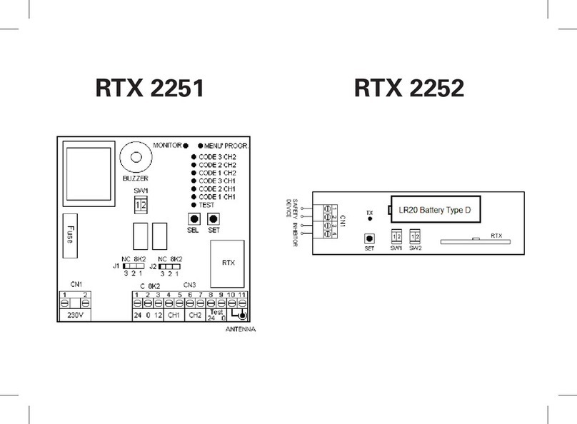
Seav RTX 2251 manual

BFT
BFT KR92522800003 Installation and user manual
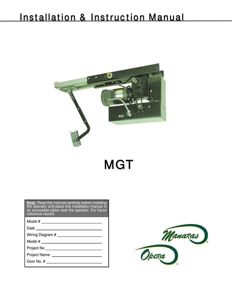
Manaras
Manaras Opera MGT Installation and instruction manual
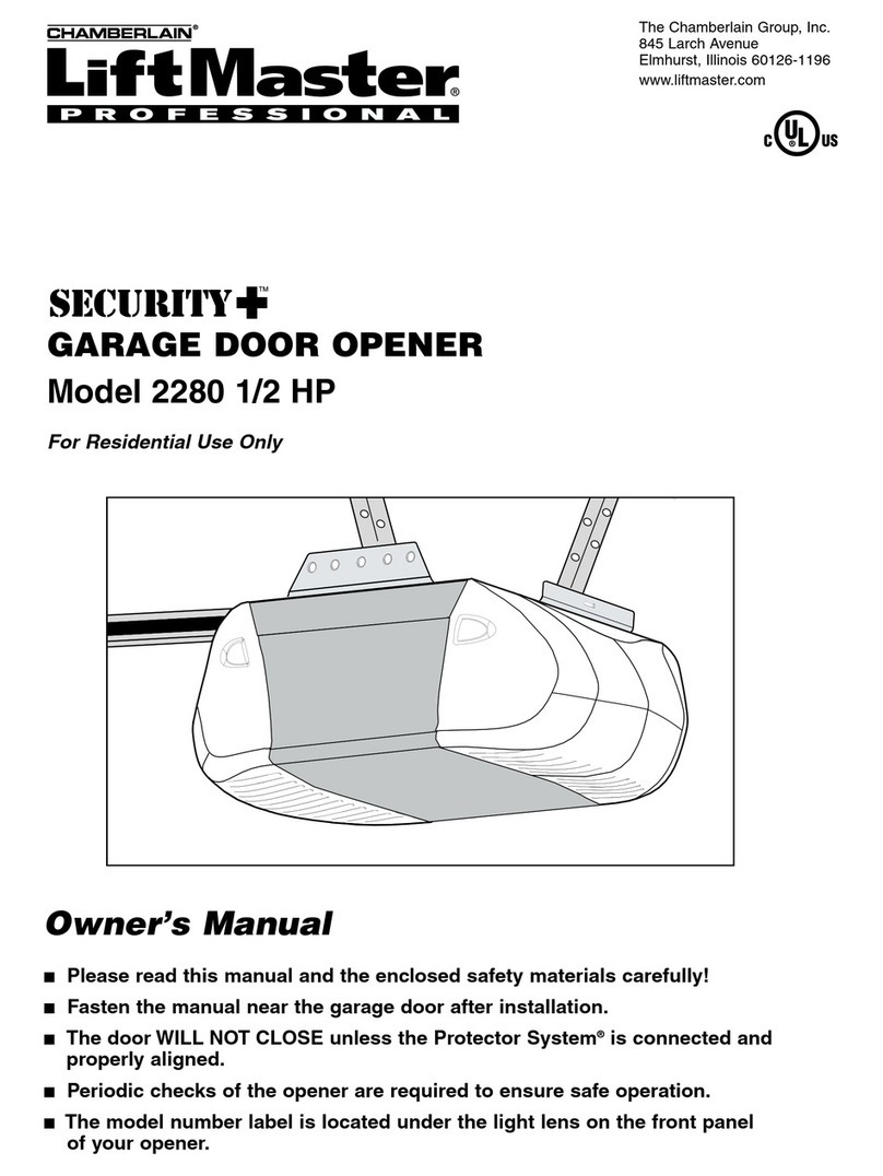
Chamberlain
Chamberlain 2280 owner's manual

CornellCookson
CornellCookson SDCL-5025 Installation instructions and operation manual
Roger
Roger AYRON Series INSTRUCTIONS AND RECOMMENDATIONS FOR THE INSTALLER

Merik
Merik LiftMaster PREMIUM Series user guide
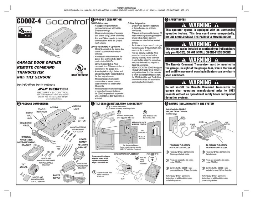
Nortek
Nortek GoControl GD00Z-4 Installation instructions manual
Chamberlain
Chamberlain LiftMaster CSW24V quick start guide

SEA
SEA Saturn 600 manual
Johnson Controls
Johnson Controls HomeLink OHHL3 user manual
