Craftex CX904 User manual

MODEL CX904
3” Mini Grinder with Rotary Shaft
Version 1

2
TABLE OF CONTENTS
General Safety Instructions ......................................................................... 3
Safety Instructions for Bench Top Grinders................................................. 5
Power Supply .............................................................................................. 6
Plug and Grounding Requirements ............................................................. 7
Unpacking Your CX904............................................................................... 8
Specifications .............................................................................................. 9
Control & Components ................................................................................ 10
Inventory...................................................................................................... 11
Assembly..................................................................................................... 12
Adjusting Spark Deflector............................................................................ 13
Operation..................................................................................................... 14
Wheel Dressing........................................................................................... 15
Installing/Removing Grinding Wheel............................................................ 16
Buffing ......................................................................................................... 17
Types of Buffing Compounds ...................................................................... 18
Using the Buffing Wheel.............................................................................. 19
Maintenance................................................................................................ 20
Trouble Shooting......................................................................................... 22
Parts............................................................................................................ 24
Parts List...................................................................................................... 25
Wiring Diagram............................................................................................ 27
Warranty...................................................................................................... 28

3
General Safety Instructions:
Operating a bench top grinder can be
dangerous if safety precautions and common
sense are not followed. The operator of the
machine should be familiar with and
understand the manual before operation of the
tool. Do not operate this bench top grinder if
you have not read the manual and are
understanding of the limitations of this
machine. DO NOT modify this machine in any
way.
Before Operation of Grinder:
WARNING!!!
In order to avoid any potential serious injury
or property damage, read and follow the
safety and operating instructions laid out in
this manual.
1.) Some debris and dust generated by use of
this bench top grinder may contain chemicals
like:
•Lead from lead-based paint
•From Crystalline silica from bricks,
cement, and other masonry
products.
•Arsenic and chromium from
chemically treated lumber
Your risk of exposure to the above listed
chemicals varies based on the type of work
being performed. Always work in a well
ventilated area and with the proper approved
safety equipment. Use of a dust mask capable
of filtering out microscopic particulates should
be worn during operation of the bench grinder.
2.) Read through the owner’s manual
thoroughly and understand how to use this
machine for its intended applications.
3.) Ground all machines. If the machine has
a 3 prong plug, it must be used in
conjunction with a 3 prong electrical
receptacle. The purpose of the third prong is
to provide grounding for the machine and to
prevent accidental electrical shock. DO NOT
under any circumstance remove the third
prong.
4.) Avoid possible hazardous working
environments. Avoid using any electrical
tools or machines and wet or damp locations.
Do not expose to rain.
5.) DO not use electrical machines or tools in
the presences of flammable gasses or
liquids.
6.) Always keep the work are clutter free and
clean. Work area should be free from debris,
slippery floors, grease, and wax.
7.) Keep children away during operation of
the machine and keep everyone out of your
immediate work area.
8.) Do not use the machine for purposes that
are not intended for which the machine was
designed.
9.) Do not wear loose fitting clothing, neck
ties, gloves, or jewelry. These items increase
the risk of serious injury as they may be
caught by the machine during operation and
pull the operator in towards the machines
moving parts. Long hair should also be
covered and kept away
from the machine
during operation to avoid getting caught as
well.

4
10.)
Childproof the workshop area by removing all
switch keys from machinery, unplugging all
equipment, or by use of padlocks.
11.) Always remove or unplug machine from
power source before performing any
maintenance or making any adjustments.
12.) Keep all protective guards in place and in
proper working order to avoid potential injury.
13.) Make sure the on/off switch is in the off
position to avoid accidental starting of the
machine when connecting to its power source.
14.) Remove all tools from work area used for
maintenance before turning machine.
15.) Use only recommended or original
accessories. Use of accessories not meant for
this machine can lead to serious injury or even
property damage. Please check the manuals
for accessories to ensure that they can be
safely used with your machine.
16.) Never leave a running machine
unattended. Wait until the machine has come
to a full stop after turning the power switch off
before leaving the area.
17.) Do not stand on tool as it could result in
serious injury or property damage.
18.) Do not store items above or around the
tool or where anyone may try and stand on the
machine to reach the items.
19.) Keep your balance. Never overextend
yourself around the machine. Make sure work
area is free from grease, oil, and other slip
hazards.
20.) Maintain your machine. Always keep
machine clean and in proper working order.
Dress the grinding wheels and replace other
abrasive accessories when worn out.
21.) Before operating machine check for any
damaged parts or accessories. Thoroughly
check all safety guards are operating as they
should and are not damaged. Also check for
the alignment, binding, breaking of moving
parts.
22.) Do not operate machine under the
influence of drugs, alcohol, medication, or
while tired.
23.) Make sure to secure all work using
clamps or jigs to secure the work piece. This is
much safer then attempting to secure the work
piece using your hands.
24.) Pay attention and stay alert while
operating machine. A second of distraction or
inattention can result in serious injury or
property damage.
25.) You should always wear a dust mask
when operating machine to avoid inhaling any
hazardous dust or airborne particulates.
Machine should be operated in a properly
well-ventilated area and in use with dust
collection when available. Long term exposure
to dust may result serious and permanent
respiratory and health conditions such as
silicosis, cancer, and even death. Always use
a NIOSH/OSHA approved respiratory
protection.
26.) If machine is used in conjunction with an
extension cord it must be heavy enough to
carry the current the machine will draw during
operation. Using a cord with a wire gauge that
is too small or too long can result in voltage
drop causing loss of power and overheating of
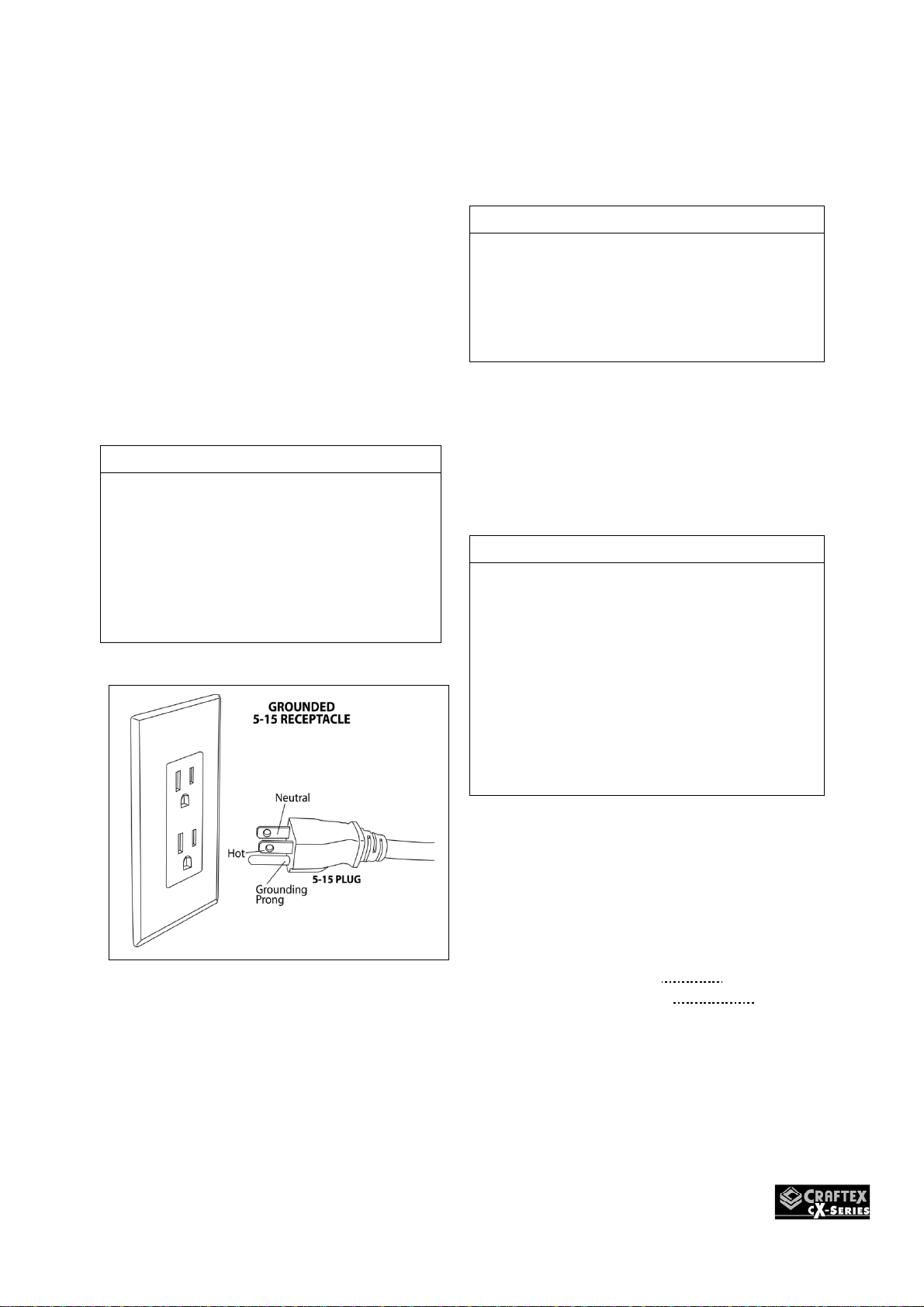
the motor. Use only 3 prong extension cords
that have grounding pin.

5
Specific Safety Instructions For Bench Top Grinders
1.) Read the instructions thoroughly and
understand before use or operation of grinder.
2.) Use eye shields and wheel guards
provided with the grinder.
3.) The Grinding wheels will decrease in
diameter with use. As the diameter changes
make sure to adjust the tool rest to keep and
maintain a distance of 1/16” from the grinding
wheel.
4.) Remove and replace any cracked or
damaged grinding wheels immediately. A
cracked or damaged wheel can cause debris
to be discharged towards the operator at a
high velocity. When replacing the grinding
wheel tighten the spindle nut just enough to
secure the wheel in place. Do not over tighten
the grinding wheel as excessive force can
damage the wheel. When choosing
replacement grinding wheels only use properly
sized wheels that are rated for the RPM of
your machine.
5.) Always stand to the side of the bench
grinder when starting the machine. Stand to
the side of the machine until it has reached full
operating speed to avoid any possibility of
being hit by debris from a damaged grinding
wheel.
6.) Do not force your work piece into the
grinding wheel. Approach the grinding wheel
with the work piece slowly so that the wheel
may have an opportunity to warm up reducing
the chances of wheel damage. Do not grind on
the sides of the grinding wheels or use coolant
or cutting liquids directly on the surface of the
grinding wheel.
7.) The Grinding wheel should be dressed
often to keep the wheel surface flat and free of
contaminates like residue or glaze.
8.) Tool rest should be kept securely in place
and used to position your work piece for
grinding.
9.) Do not operate grinder around flammable
materials as the grinder will generate sparks
and debris. Back of the grinder should be
cleaned regularly.
10.) Never bring grinding wheels to a stop by
forcing your work piece into the grinding
wheels. Let the grinder come to a stop by
itself.
11.) Allow for the grinding wheels to reach full
speed before beginning work on your material.
12.) Only use a wheel dresser to resurface the
face of the grinding wheels.
13.) Keep all safety guards in place. Do not
use the grinder if any of the guards are
damaged or missing.
14.) Secure the grinder to a workbench or
stand using bolts to avoid tipping or sliding of
the machine during operation.
15.) Make sure all wrenches and adjustment
keys are clear of the machine before turning
the grinder on.
16.) Regularly clean all dust and debris from
inside and beneath the safety guards while
machine is unplugged.
17.) Never grind small pieces of material
without being properly supported by the tool
rests or held by clamps to avoid personal
injury or property damage.

6
POWER SUPPLY
AVAILABILITY OF POWER
Before Installation of this machine, you will
need to consider the proximity of your power
supply circuit. If available circuits do not meet
the requirements for this machine you will
have to get a new circuit installed by a
licensed electrician. Use of a licensed
electrician will minimize the risks of fire,
electrocution, damage to equipment, and will
insure everything is wired in accordance to
the applicable codes and standards.
FULL LOAD CURRENT RATING
This is the amount of Amps a machine draws
under 100% of the rated output power.
FULL LOAD RATING FOR 120V
15AMPS
The full load current is not the maximum
amount of amps the machine will draw. The
machine has potential to draw current beyond
the full load rating if it is overloaded.
Overloading of the machine for an extended
period of time can cause damage,
overheating, or even fire. The risk is higher if
the machine is on an undersized circuit. To
help avoid these issues insure you are
connected to a circuit in which meets the
specified circuit requirements for this piece of
machinery.
WARNING!
Do not connect machine to power
before setup has been fully completed
to avoid risk of personal injury or
property damage.
CIRCUIT REQUIREMENTS FOR
CX904 3" MINI GRINDER
BUFFER
The CX904 has been prewired at the
factory for operation on an electrical
circuit that has a verified ground and
meets the below requirements:
Voltage: 110V – 120V
Cycle: 60Hertz
Phase: Single
Circuit Breaker Size:……………15Amps
Please Note:
1.An electrical circuit includes all electrical
equipment between the breaker panel
and the machine. This is why it is
important to have the proper circuit size
so it can safely accommodate this
machine under full load for an extended
period of time.
2.The circuit requirements laid out in this
manual are for a dedicated circuit in
which only one machine will be
operational or installed at a time. If you
choose to connect to a shared circuit
where more than one machine may be
running at a time please consult with a
qualified electrician to insure the circuit
is properly sized for safe operation.

7
PLUG AND GROUNDING
REQUIREMENTS
This machine must be grounded so that
in the event of certain malfunctions it will
reduce the chances of electrical shock
by providing a path of least resistance
for the electric current to travel through.
For this reason the CX904 comes with a
cord equipped with an equipment
grounding wire that leads in to the
grounding prong on the plug.
NOTE
The three-prong plug is only to be
plugged in to matching receptacle that
is properly installed according to the
local electrical codes and standards.
Under no circumstances should you
modify the plug to make it fit in a
receptacle that it is not meant for this
configuration. (see figure A)
Figure A
If there is an improper connection of a
machine grounding wire it may result in
a heightened risk of electric shock. If
repair or replacement of the power cord
is necessary in the future please consult
a licensed electrician.
NOTE
If ever you notice damage or ware to
either the cord or plug disconnect it
immediately from the power supply and
have it replaced by a licensed electrician
or service tech before any further use of
the machine.
USE WITH EXTENSION CORDS
If you absolutely must require the use of
an extension cord with your machine do
so, on a temporary short-term basis
only.
NOTE
We recommend that you do not use an
extension cord with this machine. Also the
longer the extension cord the greater the
possibility of voltage drop that can cause
the motor to work harder as it will be
under powered which in turn will cause it
to draw more amps. This may cause the
thermal overload to trip or even the
breaker in your electrical panel. It may
also cause the extension cord to heat up
which can be a potential fire hazard.
If an extension cord is used with this
machine it must have a ground wire with a
plug that attaches to the one currently
installed on your machine. The extension
cord must also meet the following
specifications below:
Minimum Wire Gauge: 16 AWG
Maximum Cord Length: 50 ft.

8
Unpacking Your CX904
The CX904 will require minimal assembly.
1.) Remove the contents from the carton and
place all items on a clean clutter free work
surface.
2.) Remove all packing, protective materials,
and protective coatings from machine. Use
WD40 to help breakdown the protective
coating. Just spray the WD40 on coated
areas and wipe clean with a cloth. You
may need to repeat this step a couple
times to remove all protective coating.
NOTE
Do not use gasoline, acetone, or paint
thinner to remove protective coating as
they may damage the painted areas.
3.) Compare all the items from the carton with
Figure 1. Make sure all items in the inventory
are accounted for before throwing away carton
and packaging materials.
WARNING!!!
If any parts of the machine appear to be
missing DO NOT plug in or operate the
machine. The bench grinder can only be
turned on once all the guards and
accessories have been properly installed.

9
Specifications:
Product Dimensions:
Weight....................................................................................................................... 5 lbs.
Width (side-to-side) x Depth (front-to-back) x Height........................ 6-3/4 x 5-1/4 x 6-1/4
in. Footprint (Length x Width)....................................................................3-1/4 x 3-1/4 in.
Shipping Dimensions:
Type...................................................................................................................Cardboard
Content..................................................................................................................Machine
Weight........................................................................................................................6 lbs.
Length x Width x Height................................................................................ 10 x 8 x 7 in.
Electrical:
Power Requirement................................................................ 120V, Single-Phase, 60 Hz
Full-Load Current Rating.............................................................................................0.4A
Minimum Circuit Size...................................................................................................15A
Connection Type........................................................................ Cord & Plug Power Cord
Included....................................................................................................................... Yes
Power Cord Length................................................................................................ 6-1/2 ft.
Plug Included…............................................................................................................Yes
Plug Type................................................................................................................... 5-15
Switch Type.................................................................................. Toggle ON/OFF Switch
Motors
Main Type.......................................................................................................... Induction
Horsepower.......................................................................................................... 1/14 HP
Phase........................................................................................................... Single-Phase
Amps.......................................................................................................................... 0.4A
Speed............................................................................................................... 3450 RPM
Power Transfer .............................................................................................. Direct Drive
Bearings.....................................................................Shielded & Permanently Lubricated
Main Specifications:
Operation Info Right Wheel Type............................................................ Aluminum Oxide
Left Wheel Type............................................................................................. Wool Wheel
Bore......................................................................................................................... 1/2 in.
Wheel Speed at Maximum Wheel Diameter..................................................... 3450 RPM
Construction:
Base................................................................................................................... Aluminum
Work Rest.................................................................................................................. Steel
Eye Shields................................................................................................. Polycarbonate

10
Control & Components
Figure 1
A. Safety Shield: Protective barrier that shields user from flying sparks and debris during
grinding operations. Eye protection still must be worn at all times.
B. Spark Deflector: Prevents and reduces the amount of sparking thrown back at operator
during grinding operations.
C. Tool Rest: Flat surface for resting the workpiece during operation.
D. ON/OFF Switch: Turns the motor on when pushed to the right and off when pushed to
the left.
E. Wheel Guard: Protects the operator from accidental contact with the grinding wheel and
helps to contain sparks while performing any grinding operations.
F. Rotating Shaft: Rotary tool attachment that connects to the right side of the grinder
providing additional functionality.

11
Inventory
The list of items below were shipped
with your machine. Before beginning
setup of your new machine, it is wise to
lay these items out and inventory them.
Note:
If you have trouble finding an item on
the list carefully check around inside the
packaging materials. Sometimes these
items get lost in the packaging material
whilst unpacking the machine. Items
may also be pre-installed at the factory.
Figure 2
Qty
A. 3” Mini Grinder………………………..1
B. Rotary Attachment…………………...1
Figure 3
QTY
C. Safety Shield………………………….1
D. Spark Deflector……………………….1
E. Tool Rest Left…………………………1
F. Tool Rest Right……………………….1
G. Pin Wrench………………………...…1
H. Open End Wrench 10mmx7mm……1
I. Collet Wrench………………………….1
J. Wing Bolts M4-0.7……..……………..3
K. Phillips Head Screw M4-.07x40…....2
L. Flange Nut M4-0.7….……………..…1
M. Flat Washers…………………………3
N. Phillips Head Screw M4-0.7x8..…….2
MOUNTING
The grinder features four pre-drilled
holes on its base which allow mounting
it to the workbench.
There are two ways to mount the grinder
onto the workbench; through mount and
direct mount.
"Through Mount" is the strongest
mounting option where the holes are
drilled all the way through the
workbench. Hex bolts, washers and hex
nuts are used to secure the grinder to
the workbench. (Figure 4) (Hardware not
supplied)
Figure 4 Through Mount
"Direct Mount" is to simply secure the
grinder to the workbench using lag

12
screws. See figure 5. (Hardware not
supplied)
Figure 5 Direct Mount
Assembly
With the hardware listed in the inventory
section, completely assemble the
CX904 by attaching the tool rest and
safety shield.
1. Connect safety shield to spark
deflector using (1) M4-.7 x 40 Phillips head
screws and (1) 4mm flat washer, securing it
in place with (1) flange nut as shown in
figure 6 below.
2. Connect the safety shield assembly
to right side of grinder using (2) M4-.7 x 8
Phillips head screws with captive flat lock
washers as seen in figure 6 below.
Figure 6
3. Connect each tool rest to the grinder
using (2) 4mm flat washers and (2) M4-.7 x
10 wing bolts as seen in figure 7 below.
Figure 7
Adjusting Tool Rests
The tool rest supports the workpiece
when grinding hence it is important to
adjust the tool rest correctly.
The tool rest should be positioned at
1/16" - 1/8" from the grinding wheel. As
the grinding wheel wears, and the gap
between the grinding wheel and tool rest
increases, adjust the tool rest closer to
the grinding wheel.
Figure 8
WARNING!
Do not grind without the tool rest in place.
The grinding wheel must be positioned in
place before operation. Free hand
grinding or a large gap between tool rest
and grinding wheel will increase the
possibility of kickback.

13
Adjusting Spark Deflector
The purpose of the spark deflector is to
prevent the workpiece from being
showered with sparks along with the
operator’s hands. As the wheel wears
over time, loosen the mounting screws
shown in figure 9, and adjust the spark
deflector so that it is closer to the
grinding wheel. Please note that a gap
of 1/8”-1/4” must be maintained. Once
adjusted retighten the mounting screws.
Note:
If gap reaches ¼” and there is no more
room for adjustment the grinding wheel
must be replaced at this time.
Figure 9
Test Running Machine
Once you have assembled the grinder
and verified that grinding wheel is
secured, it is then time to do a test run
and see that the machine powers up
and runs properly.
To rest run the grinder:
Remove and clear away all the tools and
objects used for assembling the
machine.
Make sure you have read and
understood the instructions given in this
user manual and your grinder is set up
properly.
Connect the cord to the power source.
Stand to the side of the grinding wheel
and turn the machine ON.
The grinder should run smoothly with
little or no vibration.
During the test run if there is any
unusual noise or vibration turn machine
off and disconnect the grinder from the
power source immediately. Check all the
parts you have assembled, once again
and try to find out the problem.

14
OPERATION
In this section of the manual, we are
providing you with the basic
understanding of the grinding operation
on this machine.
Warning!
Always wear safety glasses or a face
shield and respirator when operating the
machine. Failure to do so can result in
serious damage or injury to your eyes
and lungs.
To Operate CX904
Check the work-piece and make sure it
is suitable for grinding and select the
correct grinding wheel for the work-piece
you want to grind.
Adjust the tool rest so that it is
perpendicular to the grinding wheel and
the gap is 1/16" - 1/8"
Adjust the spark deflector so that the
gap is 1/8" - 1/4".
Make sure eye shields are in position.
Wear safety goggles or face shield and
a respirator and stand to the side of the
grinding wheel.
Connect the cord to the power source
and turn the switch to ON position.
Allow the grinding wheel to reach its full
speed and gently feed the workpiece
into the grinding wheel.
Keep the workpiece moving across the
face of the grinding wheel. Grinding
continuously on the same spot on the
wheel will cause grooves to be worn into
the wheel. The wheel may crack or
become damaged more easily and
grinding of the other objects will be
difficult.
If the workpiece becomes hot, dip it into
the water or oil to cool it preventing
surface hardening or temper loss.
If the surface of the grinding wheel is no
longer square, the wheel should be
reshaped using a wheel dressing tool or
replaced.
GRINDING WHEEL INSPECTION
The CX904 comes with an aluminum
oxide grinding wheel. The grinding
wheel should be inspected properly
before installation.
Clean the dust and/or dirt from the
surface of the wheel and inspect it for
any cracks, dents, chips, or any kind of
external damage.
To inspect the wheel for any internal
damages:
Inspect the grinding wheel and make
sure it passes the "ring-test".
Hold the wheel up with a finger through
the hole located in the middle of the
wheel and tap it using a wooden mallet
or a light non-metallic object as shown in
figure 10.
Wheels should be tapped gently with a
light wood or non-metallic instrument. A
stable grinding wheel will give a clear
metallic tone or "ring."
That distinctive ring comes from the
hardness of the material in the wheel
and its ability to transmit sound
vibrations. If the wheel is cracked, the
vibrations stop at the crack and there is
no ring. However, a ring test may not
detect all defects in a wheel, so a

15
careful visual inspection is also
necessary.
Figure 10
Warning!
Tapping wheel with heavy or metallic
objects can damage the grinding wheel.
WHEEL DRESSING
When the grinding wheel becomes
loaded and dull or the diameter of the
grinding wheel is not longer round, the
wheel should be reshaped using a
dressing tool.
Turn the grinder ON.
Position the wheel dresser on the tool
rest.
Slowly move the dressing wheel towards
the grinding wheel maintaining slight
pressure until you see a clear grinding
surface on the wheel.
Turn OFF the grinder.
Adjust the tool rest and the spark
deflector as instructed.
Wheel Care
When performing grinding operations
your safety largely depends on the
condition of the grinding wheel. A wheel
in poor condition has the possibility of
breaking apart during operation and
injuring the operator or others in the
area.
Tips to Help Avoid Breaking a Wheel
•Always store and transport the
wheels with care. Wheels can
become damaged if dropped or if
heavy objects are place on top of
them.
•Only use wheels that are compatible
and are rated for the RPM of your
grinder.
•Use the proper grinding wheel for
the application. Do not grind material
on a wheel that is not meant for the
application.
•Make sure that the grinding wheel is
mounted properly on the machine
before operation.
•Do not force the tooling into the
grinding wheel with such force that it
causes to grinder to slow down.
•Do not apply pressure to the
grinding wheel to stop it from
rotating after machine has been shut
off.
•Prevent wheel from becoming
glazed by dressing it when
necessary.
•Wheels should not be stored in
damp locations.
•Be careful not to over tighten the nut
when mounting the grinding wheel.

16
Installing/Removing Grinding
Wheel
Warning!
Always visually inspect and perform a
“ring test” on a wheel before installation.
Do not use damaged wheels for any
reason.
Installing/Removing Grinding Wheel
1. Make sure that machine is disconnected
from its power source.
2. Remove outer guard by loosening (3)
M4-.7 x 10 Phillips head screws with
captive flat and lock washers holding the
guard in place. See figure 11 on the next
page.
3. Remove the wheel guard by twisting
guard clockwise until screws align with
the access holes.
Figure 11
4. Remove M6-1 hex nut. See Figure 12
below.
Figure 12
5. Remove outer wheel flange along with
the paper disc. Note: hold grinding
wheel with free hand to stop the spindle
from turning while removing the hex nut.
6. Now remove the grinding wheel and
bushing from the spindle. Pay attention
to the fiber or paper disc between the
wheel flange and wheel. The paper disc
is there to cushion the pressure of the
wheel flanges and help to be distribute
the pressure evenly. See figure 13.
Figure 13
7. Place the inner and outer flanges on a
flat surface to verify their flatness. If
either flange appears to be warped or
damaged it must be replaced.
8. Mount the new grinding wheel and
bushing in the order displayed in figure
13. Tighten the M6-1 hex nut firmly,

17
however you must be careful not to
overtighten. Overtightening can cause
the grinding wheel to crack.
9. Re-attach the outer wheel guard using
the hardware removed in step 2.
10. While standing safely to the side of the
grinder, turn the grinder on and run the
new grinding wheel for about 1 or 2
minutes before standing in front of it.
This will protect you in the event the
wheel is damaged and comes apart.
Only use the grinding wheel if it is
running smoothly and not wobbling.
Buffing
Here are some tips below on how to get
the most out of your CX904 and buffing
wheel. Learning to effectively use your
machine and properly hold your
workpiece and knowing the amount of
pressure to apply as well as how to
move the workpiece against the wheel
and which compound to use requires a
certain amount of discovery.
•Clean all parts thoroughly that you
intend on buffing. All oil, dust, rust,
paint, or other residue must be
removed with water or chemically.
Always dry workpiece with rag after
cleaning.
•Use buffing compounds in tiny
amounts at a time. Add paste like
compounds with a wand or directly
to the part. For waxed based
polishing or stick type compounds
you will need to press the compound
against the wheel for a couple
seconds while the machine is
running. Be careful not to use too
much compound.
•Place your workpiece under the
wheel when you are applying the
compound on to the buffing wheel.
By doing this should any of the
compound drop it will land on the
workpiece and won’t be wasted on
the floor.
•To start buffing you will need to
place your workpiece on to the tool
rest and slowly start moving it
towards the buffing wheel. You must
always hold the workpiece firmly
while performing any buffing
operations. Remember placing one
hand near the contact point will
increase you control.
•Have buffing wheel raked out before
each use or when build up becomes
heavy. This will require you to clean
the wheels with a wheel rake to
remove any buildup of compounds
as well as metal particles. Always
use light pressure when using rake
to avoid damaging the buffing
wheels.
•For best results when buffing do not
mix different compounds on the
same wheel. Use different wheels
for different compounds.
•When buffing you should always
wear proper protective equipment. If
the buffer forces the workpiece from
your hand it most likely will be
coming right at you. Therefore it is
necessary to be prepared by
wearing googles or face shield as
well as a heavy leather apron. A
respirator or dust mask should also
be worn to protect your lungs from
fine metal particles.
Warning!
Always hold workpiece firmly against
tool rest while buffing as failure to do so
will cause the workpiece to be thrown
from operator’s hands resulting in
possible personal injury.

18
Types of Buffing Compounds
Most colours of the compounds have
similar applications; however, it is
always wise to check with the
manufacturer of the particular compound
you decide to use.
Red - Generally made for fine polishing
on brass or gold. This provides a
superior shine when using a loose
muslin buffing wheel.
Green (Extra Fine) – Generally used for
extra fine polishing on various metals to
help bring out the mirror like finish. Best
applied with loose muslin and spiral
sewn buffing wheels.
Green (Fine) - Slightly more abrasive
than the Green (Extra Fine) above. This
compound is great for a medium to fine
polish on most metals.
White – This compound is great for
ivory, plastics and resins when used in
conjunction with a soft spiral sewn and
soft airway buffing wheels.
Black – Meant to be used with sisal and
airway hard buffing wheels. The black
compound is perfect for the initial rough
cut on stainless steel and iron.
Tripoli – This is a middle of the road
abrasive that provides a great medium
cut for aluminum, brass, or zinc alloy.
Installing/Removing Buffing
Wheels
The CX904 has a left and right shaft to
allow for the option of mounting grinding
or buffing accessories dependent on the
application.
Warning!
Safety shield must always be installed
for all grinding operations. Failure to do
so can result in serious personal injury.
How to Install/Remove Buffing Wheel:
1. Machine must be disconnected from
its power source.
2. Loosen the (3) M4-.7 x 10 Phillips
head screws with captive flat and
lock washers that hold the wheel
guard in place.
3. Remove the outer guard.
4. Remove the M6-1 hex nut.
5. Remove the outer flange of the
buffing wheel and bushing from
spindle.
6. Now install the new buffing wheel,
bushing and wheel flange. Then
reinstall the M6-1 hex nut and
tighten firmly.
Figure 14

19
Using the Buffing Wheel:
1. Use safety glasses and respirator.
2. Select the desired polishing
compound and buffing wheel for the
application.
3. Turn the machine on and apply the
compound to the rotating face of the
buffing wheel.
4. Position workpiece for buffing.
5. Perform buffing operations outlined
in Buffing section of manual.
6. When desired results have been
achieved turn machine off.
Rotary Shaft Operations
The rotary shaft installs onto your
CX904 3” Mini Grinder to allow you to
operate in tight spaces with greater
control. Do not operate the rotary shaft
with sharp bends.
Installing Rotary Shaft:
1. Make sure machine is disconnected
from its power supply.
2. Remove cover and screw or
thread rotating shaft onto spindle
located on the right-hand side of
the grinder. (See figure 15)
Figure 15
NOTE
Hold the wrench on flats of the rotating
shaft, then rotate the grinding wheel
counter-clockwise with spare hand to
tighten.
Installing Bits in Rotary Shaft:
CX904’s rotary shaft uses cutter and bits
with a 1/8” shaft diameter.
How to Install a Bit:
1. Make sure machine is
disconnected from its power
source.
2. Now rotate the collet nut until the
locking holes in the rotary shaft are
aligned with the grip, then insert the
pin wrench. (See figure 16 below)
Figure 16
3. Turn the collet nut counter-
clockwise to loosen. Do not
remove nut from shaft
completely.
4. Insert shank of bit into the collet.
At least ½” of shank on bit should
be mounted into end of the collet.

20
5. Tighten collet nut with the pin
wrench inserted into the locking
hole.
6. Carefully tighten 1/3 of turn with
collet wrench. Do not over
tighten.
Figure 17
MAINTENANCE
:
During the life of your machine, you will
need to practice some regular
maintenance to keep your grinder in
peak performance condition. Check your
grinder routinely for damaged or loose
grinding wheels, worn power cord or
worn switch as well as any loose
hardware. The grinding wheel should be
checked regularly from any internal or
external damages. The bearings are
pre-lubricated and require no additional
lubrication.
Warning!
All maintenance should be done while
machine is turned off and removed from
its power source. Failure to do so could
result in property damage or even
serious personal injury.
Daily Maintenance:
•Check for loose mounting bolts
•Check for cracked, loose or
damaged grinding wheel
•Check for torn, damaged, loose or
severely worn buffing wheel
•Check chord for any wear or
damage.
Grinding Wheels:
Grinding wheels must be inspected
before each use. You can use a method
called the ring test that was mentioned
in the wheel inspection section of this
manual. When storing grinding wheels
you have to mindful to keep them from
potential damages by being dropped or
having other items stacked on top of
them.
Grinding wheels should be replaced
when the spark deflector or the tool rest
have not more room for adjustment and
the gap has exceeded the safe limit.
Wheel Dressing:
Your grinding wheels will require
dressing periodically dependent on the
type of grinding you do.
There are a few different types of wheel
dressing tools available. By dressing the
wheel, you are helping to restore the
abrasive qualities as well as returning
the wheel edge back to square.
Wheel Storage:
Grinding wheels are easily damaged for
that reason it is important that they are
stored properly. Grinding wheels should
be store in a location that is dry and safe
from potential damage from being
dropped or having other items stacked
Table of contents
Other Craftex Grinder manuals