Jet JPSG-618M1 Service manual

Operating Instructions and Parts Manual
6”x18” Precision Manual Surface Grinder
Model JPSG-618M1
WMH TOOL GROUP
2420 Vantage Drive
Elgin, Illinois 60123 Part No. M-414519
Ph.: 800-274-6848 Revision A 4/05
www.wmhtoolgroup.com Copyright © WMH Tool Group

2
This manual has been prepared for the owner and operators of a JET JPSG-618M1 Surface Grinder. Its
purpose, aside from machine operation, is to promote safety using accepted operating and maintenance
procedures. To obtain maximum life and efficiency from your Surface Grinder and to aid in using it safely,
please read this manual thoroughly and follow the instructions carefully.
Warranty and Service
WMH Tool Group warrants every product it sells. If one of our tools needs service or repair, one of our
Authorized Repair Stations located throughout the United States can provide quick service or information.
In most cases, a WMH Tool Group Repair Station can assist in authorizing repair work, obtaining parts, or
perform routine or major maintenance repair on your JET product.
For the name of an Authorized Repair Station in your area, please call 1-800-274-6848, or visit our web
site at www.wmhtoolgroup.com
More Information
Remember, WMH Tool Group is consistently adding new products to the line. For complete, up-to-date
product information, check with your local WMH Tool Group distributor, or visit our web site at
www.wmhtoolgroup.com
WMH Tool Group Warranty
WMH Tool Group makes every effort to assure that its products meet high quality and durability standards
and warrants to the original retail consumer/purchaser of our products that each product be free from
defects in materials and workmanship as follows: 1 YEAR LIMITED WARRANTY ON ALL PRODUCTS
UNLESS SPECIFIED OTHERWISE. This Warranty does not apply to defects due directly or indirectly to
misuse, abuse, negligence or accidents, normal wear-and-tear, repair or alterations outside our facilities,
or to a lack of maintenance.
WMH TOOL GROUP LIMITS ALL IMPLIED WARRANTIES TO THE PERIOD SPECIFIED ABOVE,
BEGINNING FROM THE DATE THE PRODUCT WAS PURCHASED AT RETAIL. EXCEPT AS STATED
HEREIN, ANY IMPLIED WARRANTIES OR MERCHANTABILITY AND FITNESS ARE EXCLUDED.
SOME STATES DO NOT ALLOW LIMITATIONS ON HOW LONG THE IMPLIED WARRANTY LASTS,
SO THE ABOVE LIMITATION MAY NOT APPLY TO YOU. IN NO EVENT SHALL WMH TOOL GROUP
BE LIABLE FOR DEATH, INJURIES TO PERSONS OR PROPERTY, OR FOR INCIDENTAL,
CONTINGENT, SPECIAL, OR CONSEQUENTIAL DAMAGES ARISING FROM THE USE OF OUR
PRODUCTS. SOME STATES DO NOT ALLOW THE EXCLUSION OR LIMITATION OF INCIDENTAL
OR CONSEQUENTIAL DAMAGES, SO THE ABOVE LIMITATION OR EXCLUSION MAY NOT APPLY
TO YOU.
To take advantage of this warranty, the product or part must be returned for examination, postage
prepaid, to an Authorized Repair Station designated by our office. Proof of purchase date and an
explanation of the complaint must accompany the merchandise. If our inspection discloses a defect, we
will either repair or replace the product at our discretion, or refund the purchase price if we cannot readily
and quickly provide a repair or replacement. We will return the repaired product or replacement at WMH
Tool Group’s expense, but if it is determined there is no defect, or that the defect resulted from causes
not within the scope of WMH Tool Group’s warranty, then the user must bear the cost of storing and
returning the product. This warranty gives you specific legal rights; you may also have other rights, which
vary from state to state.
WMH Tool Group sells through distributors only. Members of the WMH Tool Group reserve the right to
effect at any time, without prior notice, alterations to parts, fittings and accessory equipment, which they
may deem necessary for any reason whatsoever.

3
Table of Contents
Warranty and Service ..............................................................................................................................2
Table of Contents....................................................................................................................................3
Warning...................................................................................................................................................4
Introduction..............................................................................................................................................6
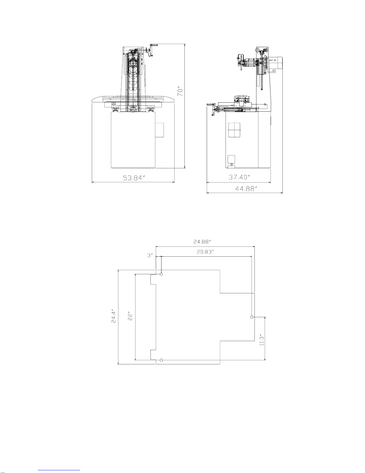
Specifications ..........................................................................................................................................6
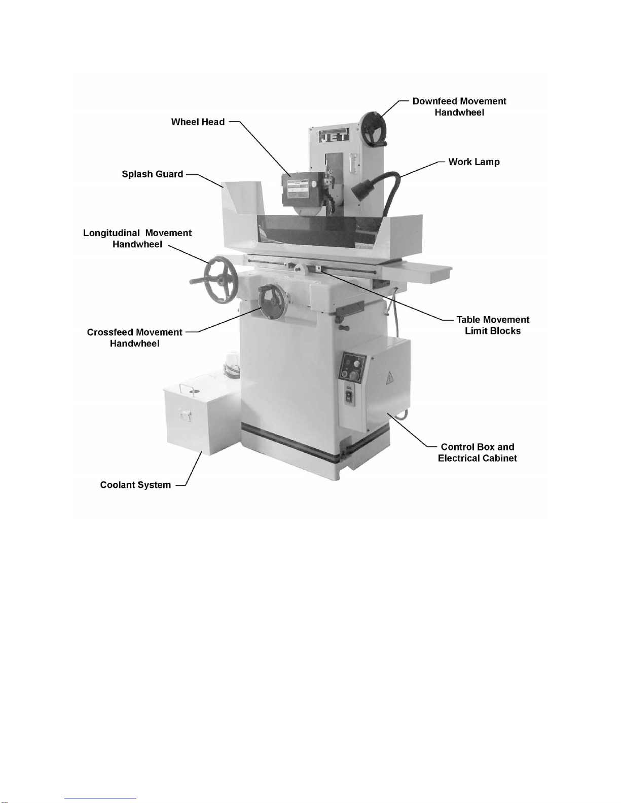
Features of the JPSG-618M1...................................................................................................................7
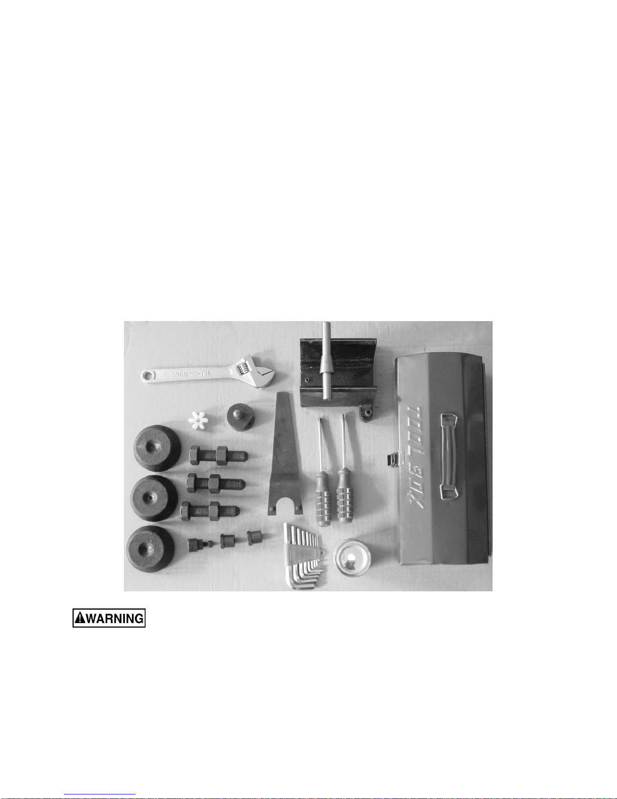
Unpacking ...............................................................................................................................................9
Contents of the Shipping Container......................................................................................................9
Installation and Assembly ......................................................................................................................10
Installing Table...................................................................................................................................11
Leveling the Machine .........................................................................................................................11
Installing Splash Guard......................................................................................................................12
Installing Coolant System...................................................................................................................12
Installing Grinding Wheel....................................................................................................................12
Removing Wheel Assembly................................................................................................................13
Wheel Dressing..................................................................................................................................13
Wheel Balancing................................................................................................................................14
Grounding Instructions...........................................................................................................................14
Extension cords..................................................................................................................................15
230 Volt, Three Phase Operation........................................................................................................15
Converting from 230 Volt to 460 Volt..................................................................................................15
Adjustments...........................................................................................................................................16
Timing Belt.........................................................................................................................................16
Operating Controls.................................................................................................................................16
Operation...............................................................................................................................................16
Longitudinal Movement of Table.........................................................................................................16
Crossfeed Movement of Table............................................................................................................16
Coolant System..................................................................................................................................17
Auto Lubrication System.....................................................................................................................17
Grinding Wheel Selection Chart.............................................................................................................18
Troubleshooting.....................................................................................................................................19
Replacement Parts................................................................................................................................19
Parts List: Spindle Assembly..............................................................................................................20
Spindle Assembly...............................................................................................................................21
Parts List: Column Assembly..............................................................................................................22
Column Assembly..............................................................................................................................26
Parts List: Saddle and Base Assembly ...............................................................................................22
Saddle and Base Assembly................................................................................................................23
Parts List: Table Assembly.................................................................................................................27
Table Assembly..................................................................................................................................29
Parts List: Base Assembly..................................................................................................................30
Base Assembly..................................................................................................................................31
Parts List: Guard and Electrical Assembly ..........................................................................................32
Guard and Electrical Assembly...........................................................................................................33
Parts List: Coolant System .................................................................................................................34
Coolant System..................................................................................................................................35
Parts List: Electrical Panel..................................................................................................................36
Electrical Panel ..................................................................................................................................37
Electrical Connections ...........................................................................................................................38

4
Warning
1. Read and understand the entire owners manual before attempting assembly or operation.
2. Read and understand the warnings posted on the machine and in this manual. Failure to comply with
all of these warnings may cause serious injury.
3. Replace the warning labels if they become obscured or removed.
4. This surface grinder is designed and intended for use by properly trained and experienced personnel
only. If you are not familiar with the proper and safe operation of a surface grinder, do not use until
proper training and knowledge have been obtained.
5. Do not use this surface grinder for other than its intended use. If used for other purposes, WMH Tool
Group disclaims any real or implied warranty and holds itself harmless from any injury that may result
from that use.
6. Always wear approved safety glasses/face shields while using this machine. Everyday eyeglasses
only have impact resistant lenses; they are not safety glasses.
7. Before operating the surface grinder, remove tie, rings, watches and other jewelry, and roll sleeves up
past the elbows. Remove all loose clothing and confine long hair. Non-slip footwear or anti-skid floor
strips are recommended. Do not wear gloves.
8. Wear ear protectors (plugs or muffs) during extended periods of operation.
9. Some dust created by power sanding, sawing, grinding, drilling and other construction activities
contain chemicals known to cause cancer, birth defects or other reproductive harm. Some examples
of these chemicals are:
• Lead from lead based paint.
• Crystalline silica from bricks, cement and other masonry products.
• Arsenic and chromium from chemically treated lumber.
Your risk of exposure varies, depending on how often you do this type of work. To reduce your
exposure to these chemicals, work in a well-ventilated area and work with approved safety
equipment, such as face or dust masks that are specifically designed to filter out microscopic
particles.
10. Do not operate this machine while tired or under the influence of drugs, alcohol or any medication.
11. Make certain the switch is in the OFF position before connecting the machine to the power supply.
12. Make certain the machine is properly grounded.
13. Make all machine adjustments or maintenance with the machine unplugged from the power source.
14. Remove adjusting keys and wrenches. Form a habit of checking to see that keys and adjusting
wrenches are removed from the machine before turning it on.
15. Keep safety guards in place at all times when the machine is in use. If removed for maintenance
purposes, use extreme caution and replace the guards immediately.
16. Check damaged parts. Before further use of the machine, a guard or other part that is damaged
should be carefully checked to determine that it will operate properly and perform its intended
function. Check for alignment of moving parts, binding of moving parts, breakage of parts, mounting
and any other conditions that may affect its operation. A guard or other part that is damaged should
be properly repaired or replaced.
17. Provide for adequate space surrounding work area and non-glare, overhead lighting.
18. Keep the floor around the machine clean and free of scrap material, oil and grease.
19. Keep visitors a safe distance from the work area. Keep children away.

5
blahblahblah
20. Make your workshop child proof with padlocks, master switches or by removing starter keys.
21. Give your work undivided attention. Looking around, carrying on a conversation and “horse-play” are
careless acts that can result in serious injury.
22. Maintain a balanced stance at all times so that you do not fall or lean against the grinding wheel or
other moving parts. Do not overreach or use excessive force to perform any machine operation.
23. Use the right tool at the correct speed and feed rate. Do not force a tool or attachment to do a job for
which it was not designed. The right tool will do the job better and safer.
24. Use recommended accessories; improper accessories may be hazardous.
25. Make sure the work piece is secured before grinding operations.
26. Turn off the machine before cleaning. Use a brush or compressed air to remove chips or debris — do
not use your hands.
27. Do not stand on the machine. Serious injury could occur if the machine tips over.
28. Never leave the machine running unattended. Turn the power off and do not leave the machine until it
comes to a complete stop.
29. Remove loose items and unnecessary work pieces from the area before starting the machine.
Familiarize yourself with the following safety notices used in this manual:
This means that if precautions are not heeded, it may result in minor injury and/or
possible machine damage.
This means that if precautions are not heeded, it may result in serious injury or possibly
even death.
- - SAVE THESE INSTRUCTIONS - -

6
Introduction
This manual is provided by WMH Tool Group covering the safe operation and maintenance procedures
for a JET Model JPSG-618M1 Surface Grinder. This manual contains instructions on installation, safety
precautions, general operating procedures, maintenance instructions and parts breakdown. This machine
has been designed and constructed to provide years of trouble free operation if used in accordance with
instructions set forth in this manual. If there are any questions or comments, please contact either your
local supplier or WMH Tool Group. WMH Tool Group can also be reached at our web site:
www.wmhtoolgroup.com.
Specifications
Model Number......................................................................................................................JPSG-618M1
Stock Number................................................................................................................................ 414519
Table Size (L x W)(in.)..................................................................................................................... 6 x 18
Grinding Capacity (L x W)(in.)............................................................................................................9 x 7
T-Slot (in.)...........................................................................................................................................9/16
Maximum Longtitudinal Manual Table Travel (in.)...................................................................................20
Maximum Cross Manual Table Travel (in.).........................................................................................7-3/4
Cross Handwheel Graduation (in.) .................................................................................................. 0.0005
Cross per Handwheel Revolution (in.)...................................................................................................0.2
Maximum Spindle Centerline to Table (in.).............................................................................................18
Vertical Handwheel Graduation (in.)................................................................................................0.0001
Vertical per Handwheel Revolution (in.)...............................................................................................0.05
Maximum Wheel Diameter (in.)................................................................................................................8
Maximum Wheel Thickness (in.) ...........................................................................................................3/4
Wheel Center Bore (in.).....................................................................................................................1 1/4
Spindle Speed (RPM).......................................................................................................................3,450
Main Motor (TEFC)......................................................................2 HP, 3 Ph, 230V/460V Prewired 230V
Floor Space Required (L x W x H)(in.).....................................................................................74 x 45 x 68
Net Weight (lbs.)...............................................................................................................................1,585
The above specifications were current at the time this manual was published, but because of our policy of
continuous improvement, WMH Tool Group reserves the right to change specifications at any time and
without prior notice, without incurring obligations.

7
Features of the JPSG-618M1

8
Dimensions and Layout

9
Unpacking
Open shipping container and check for shipping
damage. Report any damage immediately to
your distributor and shipping agent. Do not
discard any shipping material until the Surface
Grinder is installed and running properly.
Compare the contents of your container with the
following parts list to make sure all parts are
intact. Missing parts, if any, should be reported
to your distributor. Read the instruction manual
thoroughly for assembly, maintenance and
safety instructions.
Contents of the Shipping Container
1 Surface Grinder
1 Coolant Tank (with two hoses inside)
1 Balance Stand
1 Splash Guard (with 3 Sectional Pieces)
1 Table
2 Bearing Strips
1 Tool Box containing: [see photo below]
3 Leveling Blocks
3 Hex Cap Screws with Nuts
1 Hex Wrench Set (9 pcs.)
1 Adjustable Wrench
1 Cross Point Screwdriver
1 Flat Head Screwdriver
1 Dressing Diamond
1 Offset Diamond Holder
1 Can Touch-Up Paint
1 Balancing Arbor
1 Arbor Wrench
2 Square Head Bolts with Washers/Nuts
1 Wheel Extractor
1 Rubber Coupling (PN: SG1090)
1 Owner's Manual
1 Warranty Card
Read and understand the entire contents of this manual before attempting set-up
or operation! Failure to comply may cause serious injury.

10
Installation and Assembly
The Surface Grinder should
be disconnected from power during
assembly procedures.
Refer to parts breakdowns at the end of this
manual if clarification is needed for any
assembly procedure.
1. Remove the top and sides of the crate.
Leave the surface grinder bolted to the
pallet until it reaches the desired location.
2. Clean all rust protected surfaces with
kerosene or a light solvent. Do not use
gasoline, paint or lacquer thinner – these
will damage painted surfaces.
3. Cover all machined surfaces with a film of
light machine oil to inhibit rust.
4. Remove all absorption bags and any other
packing material. Remove bolts and/or
shipping straps, and remove everything
from the pallet except the Surface Grinder.
5. Use nylon straps that are rated for the
proper weight of the machine to be lifted.
See specifications. Attach the straps to the
lifting bolts. See Figure 1.
Keep people a safe distance
away from the Surface Grinder while it is
being moved.
6. The Surface Grinder must be on a solid,
level surface. If the Surface Grinder is
located next to another machine or wall, you
must leave minimum clearance of 2 feet for
maintenance and operation. Also take into
consideration the size and location of the
Coolant Tank.
7. When the Surface Grinder is in place, the
lifting lugs can remain on the machine.
8. Thread the leveling screws into the base of
the machine. Place the leveling blocks
underneath the screws, and tighten the hex
nut. See Figure 2. NOTE: You will adjust
these to level the machine after the table
has been installed.
9. Raise the wheelhead and remove the block
of wood which was used for shipping.
10. Remove the table hold-downs and socket
head cap screws. These should be saved
for future use.
11. Loosen the table lock (knurled knob) on the
right side of the table.
Figure 1
Figure 2

11
Installing Table
1. Raise the wheelhead.
2. Clean all rust protected surfaces of the table
with kerosene or a light solvent. Do not use
gasoline, paint or lacquer thinner, as these
will damage painted surfaces.
3. The bearings are in sections and are easily
installed with the dovetail connecting ends.
4. Place the 23-bearing section on the front
slide way, and the 21-bearing section on the
rear slide way. See Figure 3. Center the
bearing strips on the rail with a measuring
device.
5. With the help of an assistant, place the table
on its side, sitting on the saddle directly in
front of the rails.
6. Rotate the longitudinal handwheel to move
the fixed plate as far to the left as it will go.
Attach the table to the fixed plate with the
socket head cap screw and washer. See
Figure 4. NOTE: Be careful not to pull or
pinch the belt.
7. Move the fixed plate as far to the right as it
will go. Attach the table to the fixed plate
with the socket head cap screw and washer.
See Figure 4. NOTE: Be careful not to pull
or pinch the belt.
Leveling the Machine
Two spirit levels are needed to accurately level
the Surface Grinder.
1. Move the worktable to the middle of the
machine.
2. Set one spirit level on the table in the
longitudinal direction and the other in the
cross direction.
3. Adjust the screws over the leveling blocks
(Figure 2) until the machine is level. Check
periodically for accuracy.
Figure 3
Figure 4

12
Installing Splash Guard
1. Attach the splash guard (tall side to the left)
to the table, with four phillips pan head
machine screws and four flat washers. See
Figure 5. The rear splash plate should be
secured to the splash guard with wing nuts
and flat washers, and the tinted front splash
plate should be installed in the tabs at the
front of the splash guard.
Installing Coolant System
1. Blow out coolant tank with an air hose to
remove any dirt and debris.
2. The coolant system should be placed on the
left side of the machine.
3. Connect the hose from the coolant pump to
the fitting on the wheel guard. See Figure 6.
4. Connect the drain hose from the tank intake
to the drainage port at the left bottom side of
the saddle See Figure 7.
Disconnect machine from
power source before making electrical
connections. Electrical connections must be
made by a qualified electrician in compliance
with all relevant codes.
5. Run the power cable coming from the
coolant pump through the electrical cabinet.
Match up wires U2, V2, W2 and Ground
wire to the terminal strip. (Consult the wiring
diagrams inside the cover of the coolant
pump and electrical cabinet.)
Do not start the coolant
pump until coolant has been added.
6. The coolant should be visible, anti-high
pressure, soluble and non-foam. The
coolant must be non-flammable. Coolant
mix should be 1/60 to 1/80 for normal
surface grinding.
7. Pour the coolant mixture into the enclosure
below the coolant pump.
Installing Grinding Wheel
Visually check the wheel for any cracks or
damage. Make sure it is the correct size for your
grinder. Then proceed with a “ring” test, as
follows:
1. Suspend the wheel with your finger or a
wooden stick through the hole.
2. Using a wood mallet, tap the wheel about
45° each side of the vertical center line and
1 to 2 inches from the center.
Figure 5
Figure 6
Figure 7

13
3. A grinding wheel in good condition will give
a clear sound at any tap point. If it does not,
the wheel is damaged. Do not use
damaged wheels.
4. Place a grinding wheel onto the shaft of the
grinding wheel seat (Figure 8).
5. Place the large washer onto the shaft, then
thread the flat nut (left-hand threads; rotate
counterclockwise to tighten) onto the wheel
seat shaft. See Figure 9. Tighten the flat nut
using the provided arbor wrench.
6. To remove a grinding wheel, reverse the
above procedure.
Removing Wheel Assembly
1. To remove the complete wheel assembly,
remove the center nut (left-hand threads)
from the shaft.
2. Thread the wheel extractor into the shaft of
the wheel seat (Figure 9) and pull off the
wheel assembly.
Wheel Dressing
Dressing procedures may vary depending upon
optional accessories.
The diamond dresser seat provided with this
machine must be used with a magnetic chuck or
an overhead dresser system. These last items
are optional accessories and can be purchased
through your JET dealer.
1. Set the diamond in the overhead dresser, or
in the seat on the magnetic chuck. The
collar of the dresser is about 5°. The collar
should be turned a small degree to keep the
cutting edge in sharp condition. Use the
coolant during dressing of the wheel. Start
dressing in the center of the wheel.
2. If the grinding allowance is between .0008
and .0012 inches, the diamond should pass
through the wheel quickly.
3. If the grinding allowance is .0004 inches, the
diamond should pass through slowly.
4. Repeat the process 2 to 3 times until the
wheel is clean and its corners are square.
NOTE: Do an initial dress before balancing the
wheel to make the wheel round and true to the
spindle. After the wheel has been balanced, do
your final dress.
Figure 8
Figure 9

14
Wheel Balancing
1. Attach the wheel to the surface grinder.
2. Turn on the surface grinder and then turn on
coolant flow.
3. Dress the wheel (see instructions above).
4. Remove the dresser, turn off the coolant
and dry-run the wheel for ten minutes to
remove any coolant.
5. Turn off the surface grinder and disconnect
the machine from power source.
6. Remove the center nut and pull the wheel
assembly off the shaft using the wheel
extractor. Wipe out the inside of the wheel
assembly.
7. Wipe off the balancing arbor and insert it
into the wheel assembly.
8. Place the wheel assembly on the balancing
stand (Figure 10) and mark its gravity center
“S” with chalk. See Figure 11.
9. Insert a balancing weight “G” directly
opposite of gravity center “S” (Figure 11).
10. Determine which side is heavier, “G” or “S”.
11. Insert two balancing weights “K” on the
lighter side. If the wheel is still out of
balance, adjust “K” for balance. See Figure
11.
12. After balancing, do a final dressing of the
grinding wheel.
Grounding Instructions
Electrical connections must
be made by a qualified electrician in
compliance with all relevant codes. This
machine must be properly grounded to help
prevent electrical shock and possible fatal
injury.
This machine must be grounded. In the event of
a malfunction or breakdown, grounding provides
a path of least resistance for electric current to
reduce the risk of electric shock.
Improper connection of the equipment-
grounding conductor can result in a risk of
electric shock. The conductor with insulation
having an outer surface that is green with or
without yellow stripes, is the equipment-
grounding conductor.
If repair or replacement of the electric cord or
plug is necessary, do not connect the
equipment-grounding conductor to a live
terminal.
Figure 10
Figure 11

15
Check with a qualified electrician or service
personnel if the grounding instructions are not
completely understood, or if in doubt as to
whether the tool is properly grounded.
Repair or replace a damaged or worn cord
immediately.
Make sure the voltage of your power supply
matches the specifications on the motor plate of
the Surface Grinder. The machine should be
connected to a dedicated circuit.
Extension cords
The use of an extension cord is not
recommended for the Surface Grinder. But if
one is necessary, make sure the cord rating is
suitable for the amperage listed on the
machine’s motor plate. An undersize cord will
cause a drop in line voltage resulting in loss of
power and overheating.
Use the chart in Figure 12 as a general guide in
choosing the correct size cord. If in doubt, use
the next heavier gauge. The smaller the gauge
number, the heavier the cord.
230 Volt, Three Phase Operation
Th Surface Grinder is factory-wired for 230 volt,
but can be converted to 460 volt if so desired
(see “Converting From 230 Volt to 460 Volt”).
You may either install a plug or “hard-wire” the
Band Saw directly to a control panel.
If you are connecting a plug, use a proper UL
listed 3-pole, 4-wire grounding plug suitable for
230 volt operation.
If the Band Saw is to be hard-wired to a panel,
make sure a disconnect is available for the
operator. During hard-wiring of the Band Saw,
make sure the fuses have been removed or the
breakers have been tripped in the circuit to
which the Band Saw will be connected. Place a
warning placard on the fuse holder or circuit
breaker to prevent it being turned on while the
machine is being wired.
Converting from 230 Volt to 460 Volt
There are two motors on this machine
(Wheelhead Motor and Coolant Motor) that must
be rewired for 460 volt. Consult the wiring
diagram inside the electrical box of each motor.
Also, the transformer in the machine’s electrical
box must be switched to 460V operation.
If using a plug, install a proper UL listed plug
suitable for 460V operation.
Recommended Gauges (AWG) of Extension Cords
Extension Cord Length *
Amps 25
feet 50
feet 75
feet 100
feet 150
feet 200
feet
< 5 16 16 16 14 12 12
5 to 8 16 16 14 12 10 NR
8 to 12 14 14 12 10 NR NR
12 to 15 12 12 10 10 NR NR
15 to 20 10 10 10 NR NR NR
21 to 30 10 NR NR NR NR NR
*based on limiting the line voltage drop to 5V at 150% of the
rated amperes.
NR: Not Recommended.
Figure 12

16
Adjustments
Timing Belt
The timing belt should have 1/2” to 3/4” give with
six pounds of pressure applied. The timing belt
has been properly tensioned at the factory and
should not be adjusted when you receive the
machine.
As the machine receives use, however, the
timing belt may eventually need tightening. To
tension the timing belt:
1. Move the table to the left.
2. Loosen one of the hex nuts (A, B, Figure 13)
and turn the socket screw (C, Figure 13)
with a hex wrench as needed.
3. After getting the desired tension, tighten the
hex nuts (A, B, Figure 13) against the plate.
Operating Controls
(Figure 14)
The emergency stop button remains engaged
after being pushed; to re-start the machine,
rotate the stop button until it pops back out.
NOTE: The machine will not start if the electrical
cabinet is open.
Operation
Longitudinal Movement of Table
1. Loosen the socket head cap screws in the
limit blocks (A, Figure 15), and slide the limit
blocks to the desired position. Retighten the
socket head cap screws.
2. Move the table using the handwheel (B,
Figure 15) and lock the table in position by
tightening the knurled knob (C, Figure 15).
Crossfeed Movement of Table
The crossfeed handwheel (D, Figure 15) has a
scale for precision setting. The crossfeed
movement of the table can be locked by
tightening the knurled knob on the column (E,
Figure 15).
Figure 13
Figure 14
Figure 15

17
Maintenance
Disconnect machine from the
power source before doing any maintenance.
Failure to comply may cause serious injury.
Coolant System
Check coolant level once a week.
Change coolant after every 100 hours of use, as
follows: Remove coolant tank lid, and dispose of
the old coolant properly. Clean out the tank with
hot soda water. Pour in water/coolant mix to fill
the tank. (Pour the water slowly to minimize
bubbles.) After changing coolant, wash hands
and arms thoroughly.
Periodically check the coolant pump to make
sure all connections are tight.
Auto Lubrication System
The auto lubrication system lubricates the table
slideways, elevating leadscrew and crossfeed
leadscrew. The system operates whenever the
spindle is turning.
Open the upper rear panel and check the oil
level – it should reach halfway in the reservoir.
Add Mobil Vactra® Oil No. 2 to the reservoir if
the level falls below the halfway mark.
Completely change the oil every three months
using the drain valve (remove lower rear panel
to access the valve).
The oil distributor comes pre-adjusted from the
factory and should not require any further
adjustment.

18
Grinding Wheel Selection Chart
To obtain an accurate, finished surface the proper grinding wheel must be used.
Wheel Specification
Material to be ground Hardness Under 8” Under 14”
Under HRC 25 WA
A 46K WA
A 46K
Carbon Steel
Steel Plate
Carbon Steel
Carbon Steel Pipe
Forging Carbon Steel
Cast Carbon Steel Above HRC 25 WA
A 46J WA
A 46J
Nickel Chrome Steel
Nickel Chrome
Molybdenum Alloy Steel
Chromium Steel
Under HRC 55 WA 46J WA 46J
Alloy Steel Chrome Molybdenum Steel
High Carbon Alloy Steel
Alloy Cast Steel
Tool Carbon Steel
Above HRC 55 WA 46I WA 46H
High Speed Steel Under HRC 60 WA 46I WA 46H
Tool Steel Alloy Tool Steel Above HRC 60 WA 46H WA 46G
Stainless Steel WA 46I WA 46H
Stainless
Steel Anti-Heat Steel WA 36J WA 30J
Gray Cast Iron C 46J C 46I
Special Cast Iron GC 46I GC 46H
Malleable Cast Iron WA 46K WA 46J
Cast Iron
Forging Cast Iron
Brass C 30J C 30I
Bronze A 46K A 46J
Aluminum Alloy C 30J C 30I
Nonferrous
Metal
Cemented Carbide GC 60 ~ 100HI
Diamond Wheel
KEY:
Abrasives
A = Regular Aluminum Oxide
WA = White Aluminimum Oxide
C = Regular Silicon Carbide
GC = Green Silicon Carbide
Grit Sizes
30, 36, 46
Hardness
A (softest) through Z (hardest)

19
Troubleshooting
Trouble Probable Cause Remedy
Excess machine vibration. Make sure machine is level and on a
solid surface.
Check the spindle.
Grinding wheel is not balanced. Dress and balance the wheel.
Frequent wave on the
surface of workpiece.
Wheel is too hard.
Use a softer wheel.
Use a rough wheel.
Reduce the feed amount.
Improper operation.
Dress the wheel. Make sure wheel
edge is parallel with workpiece.
Slow down your crossfeed.
Make sure workpiece is securely
fastened to the table.
Minor scratch on the
surface.
Improper dressing of wheel.
Tighten the dresser.
Use proper dressing speed.
Don’t dress too deep at one time.
Improper operation. Reduce feed amount.
Use proper crossfeed speed.
Improper heat treatment. Perform heat treatment again.
Burning spots and
cracks.
Unsuitable grinding wheel. Dress the wheel finely and frequently.
Use a softer and rougher wheel.
Poor grinding ability,
wheel clogs and
workpiece shows
burns. Wheel is too hard.
Increase table and crossfeed speeds.
Reduce the wheel diameter or width.
Use a sharp diamond for dressing.
Use a rougher wheel.
Wheel dulls and grit
falls off. Wheel is too soft.
Reduce table and crossfeed speed.
Increase wheel diameter if possible.
Lightly dress the wheel, repeatedly.
Replacement Parts
Replacement parts are listed on the following pages. To order parts or reach our service department, call
1-800-274-6848 between 7:30 a.m. and 6:00 p.m. (CST), Monday through Friday. Having the Model
Number and Serial Number of your machine available when you call will allow us to serve you quickly and
accurately.

20
Parts List: Spindle Assembly
Index No. Part No. Description Size Qty
A1 ............618M1-01A1 ........... Complete Wheel Assembly ............................ ...................................1
1...............SG1202................... Balancing Arbor................................................. ...................................1
2...............SG1206................... Wheel Extractor................................................. ...................................1
3...............SG1083................... Nut .................................................................... ...................................1
4...............618M-164................ Grinding Wheel.................................................. 203x31.75x12 mm ......1
A2 ............618M1-01A2 ........... Grinding Wheel Seat........................................ ...................................1
5...............SG1082................... Wheel Setting Nut.............................................. ...................................1
6...............SG1081................... Wheel Washer................................................... ...................................1
7...............SG1079................... Wheel Hub......................................................... ...................................1
8...............SG1080................... Balance Block.................................................... ...................................1
9...............618M1-019.............. Steel Ball........................................................... ...................................1
10.............TS-1523031............ Socket Set Screw .............................................. M6x12 ........................3
A3 ............618M1-01A3 ........... Balance Stand Assembly................................. ...................................1
11.............TS-1524041............ Socket Set Screw .............................................. M8x16 ........................1
12.............SG1201...................Balance Stand................................................... ...................................1
13.............TS-1504051............ Socket Head Cap Screw.................................... M8x25........................2
A4 ............618M1-01A4 ...........Complete Wheel Cover.................................... ...................................1
14.............618M1-0114............ Lock Screw........................................................ ...................................1
15.............SG1085................... Wheel Guard Door............................................. ...................................1
16.............618M1-0116............ Retaining Ring................................................... E8...............................1
17.............SG1084................... Wheel Guard ..................................................... ...................................1
18.............618M-149................ Cross Head Screw............................................. M5x8..........................2
19.............SG1086................... Cover................................................................. ...................................1
A5 ............618M1-01A5 ...........Complete Spindle Assembly........................... ...................................1
20.............TS-1522011............ Socket Set Screw .............................................. M5x5..........................1
21.............SG1078...................Setting Nut......................................................... ...................................1
22.............SG1077................... Collar................................................................. ...................................1
23.............SG1076...................Pressing Plate ................................................... ...................................1
24.............618M-154................ Ball Bearing....................................................... NN3006K....................1
25.............SG1075...................Spacing Ring..................................................... ...................................1
26.............SG1074................... Spindle.............................................................. ...................................1
27.............1020A-292 .............. Key.................................................................... 6x6x20 mm.................1
28.............618M-142................ Angular Bearing................................................. 7204C.........................2
29.............SG1073................... Bearing Washer................................................. ...................................1
30.............SG1072................... Bearing Washer................................................. ...................................1
31.............618M1-0131............ Setting Nut.........................................................AN04..........................2
32.............TS-1503061............ Socket Head Cap Screw.................................... M6x30........................6
33.............SG1069...................Spindle Housing................................................. ...................................1
34.............SG1070................... Rear Cover........................................................ ...................................1
35.............TS-1503081............ Socket Head Cap Screw.................................... M6x35........................4
36.............SG1088................... Coupling............................................................ ...................................1
37.............TS-1503011............ Socket Set Screw .............................................. M6x6..........................1
38.............TS-1503021............ Socket Set Screw .............................................. M6x8..........................1
Table of contents
Other Jet Grinder manuals