STEELE PRODUCTS SP-PB008 User manual

Owner's Manual
©hGrind
SP-PBO08
C_U_S
226002
TLG=2OOL4
r_ WARNING!ToReduceTheRiskOfInjury,User
FORSERVICECALL:@Q@ Oa_ _0@t
PAR#= SERVlClO LLAME: LlUU=e,J_,8=W, JU_,J &
Owner's Manual
CONTENTS
Product Specifications........................................................... 1
Description..................................................................... 1
GeneralSafetyInformation ........................................................ 2
Specific SafetyRulesForTheBenchGrinder.......................................... 3
GeneralSafetyInformation ........................................................ 4
AssemblyAnd Installation ......................................................... 6
Troubleshooting ................................................................ 9
Wiring Diagramand KnowYour BenchGrinder........................................ 10
Partsand List .................................................................. 11
Warranty..................................................................... 13
PRODUCTSPECIFICATIONS
MODEL WHEEL
RatingVoltage 120Vac Diameter 8 in.
Frequency 60Hz Face l in.
Amperes 4.8 Hole 5/8 in.
No LoadSpeed 3450 RPM WORKLIGHT
Weight 38Ibs RatingVoltage 12V
HP 3/4 Watt 10W
Base Cast Iron
DESCRIPTION
Uniquedesignwith 2fixed work light to illuminateyour work area;Dry doubleend grinding wheels
can giverapid sharpeningto varioustypes of blades.Powerfulmotor quickly bringsthe coarse
andfine grinding wheelstotheir requiredoperatingspeed.
WARNING Topreventaccidentalstartingorelectricalshockthatcouldcausepossible
seriouspersonalinjury,assembleall partstoyourbenchgrinderbeforeconnectingitto power
supply.Thebenchgrindershouldneverbeconnectedtopowersupplywhenyouareassembling
parts,makingadjustments,installingorremovinggrindingwheels,cleaning,orwhennotinuse.

Owner's Manual
GENERALSAFETYINFORMATION
To operatethistool,readthisinstructionmanualand allthe labelsaffixedtothe benchgrindercarefully
beforeusing. Keepthismanualavailablefor futurereference.Safetyisa combinationofcommonsense,
staying alertand knowing howyour benchgrinder works.
1. WORKAREA
Keepthe work areacleanand well lit. Cluttered benchesanddark areasinviteaccidents.Donot use
the tool in explosiveatmospheres,such asin the presenceofflammable liquids, gases,or dust.
Powertools createsparkswhich mayignitethe dust or fumes.Keepbystanders,visitors, andchildren
awaywhile operating a powertool. Distractions cancauseyou to losecontrol.
2. ELECTRICALSAFETY
3,
Groundedtools must be pluggedinto an outlet properly installedand groundedin accordancewith
all codesand ordinances.Neverremovethe grounding prong or modifythe plug in anyway. Donot
useanyadapterplugs. Checkwith a qualifiedelectricianifyou arein doubtas to whetherthe outlet
is properlygrounded. If thetool electricallymalfunctionsor breaksdown, groundingprovidesa low
resistancepathto carry electricityawayfrom the user. Avoid contactwith groundedsurfacessuch
aspipes, radiators, ranges,andrefrigerators.There isan increasedriskof electricalshock ifyour
body is grounded.Donot exposepowertools to rain or wet conditions. Waterenteringa powertool
will increasethe risk of electricshock.
Do not abusethe cord. Never usethe cord to carry the tool or pull the plug from an outlet. Keep
the cord away from heat,oil, sharp edgesor moving parts. Replacedamagedcords immediately.
Damagedcords increasethe riskof electricshock.
Whenoperating a powertool outside, usean outdoor extension cord marked"W-A"or "W'. These
cords areratedfor outdoor useand reducethe risk of electricshock.
PERSONALSAFETY
Stayalert, watchwhat you aredoing, andusecommon sensewhen operatinga powertool. Do not
usethe tool whenyou are tired or underthe influenceof drugs, alcohol, or medication.A moment
of inattention while operating powertools may resultin serious personalinjury Dressproperly. Do
not wear looseclothing or jewelry.Wear protective hairnettingto contain long hair.Keepyour hair,
clothing,and glovesawayfrom movingparts.Rubberglovesandnon-skidfootwearare recommended
when working outdoors.
Avoid accidentalstarting. Makesure the switch is off before plugging in. Carryingtools with your
finger on the switch or plugging in tools that havethe switch on invitesaccidents.
Removeadjustingkeysor switchesbeforeturning the tool on. A wrenchor a keythat isleftattached
to arotating part of thetool mayresult in personalinjury. Donot overreach.Keepproper footing
and balanceatall times. Properfooting and balanceenablesbettercontrol of the tool in unexpected
situations. Usesafety equipment. Alwayswear eyeprotection. Dust mask, non-skid safety shoes,
hard hat, or hearingprotection must beusedfor appropriateconditions.
4. TOOLUSEANDCARE
Do not forcethe tool. Usethe correct tool for your application.Donot usethe tool ifthe switch does
not turn it onor off. Any tool that cannot be controlledwith the switch is dangerousand must be
repaired.Disconnectthe plug from the power source beforemakinganyadjustments, changing
accessoriesor storing the tool. Such preventivesafety measuresreducethe risk of starting the tool
accidentally.Store idletools out of reachof children andother untrained persons.
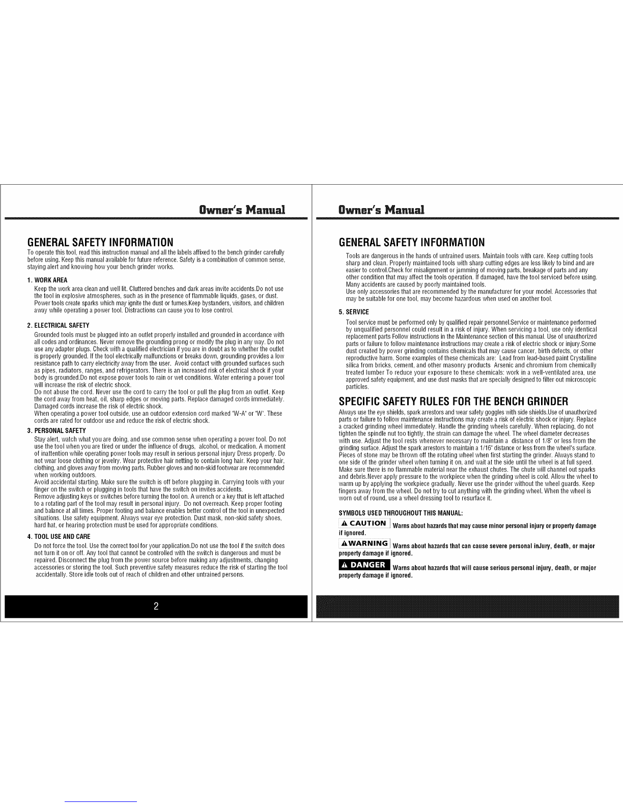
Owner's Manual
GENERALSAFETYINFORMATION
Toolsaredangerousinthe handsof untrainedusers. Maintaintools with care.Keepcutting tools
sharpand clean. Properlymaintainedtools with sharp cutting edgesare less likelyto bind andare
easierto control.Checkfor misalignmentor jamming of movingparts, breakageof partsandany
other conditionthat mayaffectthetools operation. Ifdamaged,havethetool servicedbeforeusing.
Manyaccidentsare causedby poorly maintainedtools.
Useonly accessoriesthat are recommendedbythe manufacturerfor your model. Accessoriesthat
may besuitablefor onetool, maybecomehazardouswhen used on anothertool.
5. SERVICE
Toolservice mustbeperformedonlyby qualifiedrepairpersonnel.Serviceor maintenanceperformed
by unqualified personnel couldresult in a risk of injury. When servicing atool, useonly identical
replacementpartsFollowinstructions inthe Maintenancesectionof this manual.Useof unauthorized
partsor failureto follow maintenanceinstructions may createa risk of electricshockor injury.Some
dust createdby power grinding contains chemicalsthat may causecancer,birth defects, or other
reproductiveharm.Someexamplesofthesechemicalsare: Leadfrom lead-basedpaintCrystalline
silicafrom bricks, cement,andother masonry products Arsenic and chromium from chemically
treated lumber To reduceyour exposure to these chemicals: work in a well-ventilated area, use
approvedsafetyequipment, andusedust masksthat arespeciallydesignedto filter out microscopic
particles.
SPECIFICSAFETYRULESFORTHEBENCHGRINDER
Alwaysusethe eyeshields,sparkarrestorsandwearsafetygoggleswith sideshields.Useof unauthorized
parts or failureto follow maintenanceinstructions may createa risk of electricshockor injury. Replace
acrackedgrinding wheel immediately.Handlethe grinding wheels carefully.When replacing,do not
tighten the spindle nut too tightly, the strain candamagethe wheel.Thewheeldiameter decreases
with use. Adjust the tool restswhenever necessaryto maintain a distance of 1/8" or lessfrom the
grindingsurface.Adjustthesparkarrestorsto maintaina1/16"distanceor lessfrom thewheel'ssurface.
Piecesof stonemay bethrown off the rotating wheelwhen first starting the grinder. Always standto
one sideof the grinder wheelwhen turning it on, and wait atthe side until the wheel isatfull speed.
Make surethere is no flammablematerial nearthe exhaustchutes. Thechute will channel outsparks
and debris.Neverapply pressureto the workpiecewhenthe grinding wheel is cold. Allow the wheelto
warm up by applyingthe workpiecegradually.Neverusethe grinder without the wheelguards. Keep
fingers awayfrom the wheel. Do not try to cut anythingwith the grinding wheel.Whenthe wheel is
worn out of round, usea wheeldressingtool to resurface it.
SYMBOLSUSEDTHROUGHOUTTHISMANUAL:
_tAUT!ON IWarnsabouthazardsthatmaycauseminorpersonalinjuryorpropertydamage
if ignored.
_WARN!NG IWarnsabouthazardsthatcancauseseverepersonalinJury,death,ormajor
propertydamageif ignored.
_Warnsabouthazardsthatwillcauseseriouspersonalinjury,death,or major
propertydamageif ignored.

Owner's Mariu!!
GENERALSAFETYINFORMATION
_w_!m_ WARNING:INALLCASES,MAKECERTAINTHERECEPTACLEIN QUESTIONIS
PROPERLYGROUNDED.IFYOUARENOTSUREHAVEAQUALIFIEDELECTRICIANCHECKTHE
RECEPTACLE.
DONOTMODIFYTHEPLUGPROVIDED.Ifitwill not fit the outlet,
havethe proper outlet installed byan electrician.iMPROPER
CONNECTIONof the equipment ground conductor can result
m risk of electricshock.The conductorwith the greeninsulation
(with or without yellowstripes) isthe equipmentgrounding conductor.
If repairor replacementof theelectriccord or plug isnecessary,
DONOTconnectthe equipmentgroundingconductorto a liveterminal
a liveterminal
EXTENSIONCORDS
Useproper extensioncords. Makesureyour extensioncord isin good condition and isa 3-wire
extensioncord which hasa 3-prong groundingtype plugand matchingreceptaclewhichwill accept
the machine'splug. Whenusing anextension cord, besureto useone heavyenoughto carrythe
currentof the machine.An undersizedcordwill causea drop in line voltage, resulting in loss of power
and overheating.Thetable, showsthecorrect gaugeto usedependingon the cordlength. If in doubt,
usethe next heaviergauge.Thesmallerthe gauge number,the heavierthe cord.
MINIMUM GAUGEEXTENSIONCORD
RECOMMENDEDSIZES FORUSEWiTH STATIONARY ELECTRICMACHINE-
Ampere TotalLength
Rating Volts ofCordin Feet
0-6 120 upt0 25
0-6 120 25-50
0-6 120 50-100
0-6 120 100-150
6-10 120 upt0 25
6-10 120 25-50
6-10 120 50-100
6-10 120 100-150
10-12 120 upt0 25
10-12 120 25-50
10-12 120 50-100
10-12 120 100-150
12-16 120 upt0 25
12-16 120 25-50
12-16 120
Gaugeof
ExtensionCord
18AWG
16AWG
16AWG
14AWG
18AWG
16AWG
14AWG
12AWG
16AWG
16AWG
14AWG
12AWG
14AWG
12AWG
GREATERTHAN 50 FEETNOT RECOMMENDED
Owner's Manual
GENERALSAFETYINFORMATION
UNPACKING
After unpackingthe unit, inspectall componentsfor any damagethat mayhaveoccurred in transit.
Readthe following precautionsand instructions beforeyou attach. Failureto comply with these
instructions could resultin personalinjuryor propertydamage.Keepthese instructionsin a convenient
locationfor future reference.Thefollowing itemsare includedwith your bench grinder.
ToolRest(Left&Right)&AdjustingKnob
Eyeshields(Plain&withMagnifier)
EyeshieldsMountingHardwareKit
WARNING Ifanypartsaremissingdonotoperatethistooluntilthemissingpartsare
replaced.Failuretodosocouldresultinpossibleseriouspersonalinjury.Call888-896-6881
forreplacementparts.

Owner's Mariu!!
ASSEMBLYANDINSTALLATION
,&WARN!NG Alwaysdisconnectthebenchgrinderfromthepowersourcebeforeperforming
anyassemblyguard.oradjustment.Failuretodosocouldresultinaccidentalstartingandpossible
seriouspersonalinjury.
EyeshieldAssembly(Fig 1)
1. Fastenthe safety shieldto the shield bracket usingthe adjusting knob and smallwasher.
NOTE:Theslotted partof the safety shieldbracket must facetowards the grinding wheelguard.
2.Attachthe safetyshieldassemblyandbracketto the work wheelguard usinga washer, lockwasher
and rearshield bracket knob.
ADJUSTING
KNOB
WASHER
f
SMALL
WASNER
NGH_)
Fig, Fig 2
Toolrestassembly(Fig2)
3. Removethe adjusting knob, starwasher, and washerfrom the carriage bolt onthe lower portion
ofthe wheel. (Fig.2)
4. Usingthe slottedscrew, star washer,washer andadjusting knob, attachthetool rest bracketto
the insideof the wheelguard asshown.
NOTE:Thegroovedtool restmounts onthe leftside.
NOTE:the tool rest bracket'slower slot must bepositioned overthe pin onthe guard.
With the remaining adjusting knob, installthe tool rest to the bracket.
NOTE:Adjustthe distancebetweenthe wheelandthe tool restto maintain1/16 in. or less separation
as the diameterof the wheeldecreaseswith use.
Owner's Manual
ASSEMBLYAND INSTALLATION
INSTALLATION(Fig. 3)
MountingGrinderToa WorkBench
Ifgrinder isto beusedinapermanent location,it shouldbefastenedsecurelyto a firm supporting
surface,suchas a workbench.
1. Use 1/4 in. bolts, washers,and nuts (not included).Thebolt length should be1-1/2 in. plusthe
thickness of the workbench.
2. Locateand markthe holeswherethe grinder isto bemounted.
3. Drill four 3/8 in. diameterholesthrough workbench.
4. Placegrinder onworkbench, aligning holes in basewith holes drilled Inworkbench.
5. Insertfour 1/4 in.diameter bolts, flat washers,lock washerand attachhex nuts securely.
OPERATION
_WARNiNG / Alwayswear safetygoggles
or safetyglasseswith sideshieldsduring
power tooloperation or whenblowingdust•
If operationis dusty,wear a dustmask.
If operationisdusty,weara dustmask.
Tobe efficientand work asdesigned,your tools should Lock
be keptsharp. Dulltools can andwill cause HexNut
accidents. BenchGrinders areidealfor sharpeningtools
such aschisels, planerblades,scissors, etc., Fig.3Mounting grinder to the workbench.
andfor removing rust or corrosion.
,&WARNING] Neversharpenor grindanythingmadeof aluminum•
•EyeshieldAdjustment
Thesee-through eyeshieldallows usersto seeoperationclearlyand work precisely. Eyeshieldscan
beadjusted upand down.
2. ToolRestAdjustment
Theappropriateadjustment of tool rests providesthe correct working angleto do efficientgrinding.
Thisadjustment can bedone byregulating its relatedadjusting knob. Dueto normalwear of the
grinding wheel,it is necessaryto adjust the tool rest.
3. SpeedAdjustment
Thegrinder is equippedwith a variablespeedcontrol knob. Whenthe variablespeedcontrol knob
is positionedto thefurthermost left position (counter clockwise), the RPM is2000. Therotation
increasesasthe knob is turned clockwise. RPMis3450.
MAINTENANCE
_WARNING IWhenservicing,useonlyidenticalreplacementparts.Useofanyother
partmaycreatehazardorcauseproductdamage•
General
Keepthebenchgrinderclean.Frequentlyremovedustfromworkingpartsandbeneaththegrinder.
MakesurethebenchgrinderoperatesproperlyFrequentlycheckscrews,nuts,andboltsfortightness.
NOTE:Thisbenchgrinderhasmadesufficientlylubricatedatthefactory,therefore,thebench
grinderdoesnotneedanyadditionallubricationduringthelifetimeofthegrinder.

Owner's Manual
ASSEMBLYANDINSTALLATION
Wheel Replacement (Fig. 4)
_WARNiNG ITurnthe power switch off and remove the plug from the outlet before
adjustingor maintainingthegrinder.Donotattempttorepairor maintainthemotorelectrical
components. Thisshould only be done by aqualified service technician.
If you must replaceagrinding wheel, besure to obtainone with a safe ratedspeedat leastas high as
the "noload speed"RPMmarked onthe dataplateof the grinder.Toreplacethe grinding wheel,
removethe wheelguard cover bylooseningthe screws, next, loosenthe wheelnut in aclockwise
direction for the left side and acounterclockwisedirection for the right side.Removethe outer flange
and grindingwheel.To installa newgrinding wheel, reversethe aboveprocedure.Besurethe grinding
wheeland outer flangeare properly seatedonthe spindleshaft.
Electrictools usedon fiberglass material,wallboard, spackling compounds,or plasterare subjectto
acceleratedwearand possible prematurefailure becausethefiberglasschipsandgrindings arehighly
abrasiveto bearings,brushes,commutators, etc. Consequently,we do not recommendedusingthis
tool for extendedwork onthesetypes of materials.However,if you dowork with any ofthesematerials,
it is extremelyimportant to cleanthetool usingcompressed air.
Fig ,5 Fig 4
WORKLIGHT BULBREPLACEMENT(Fig. 5)
1. Unplugthe grinder.
2. Removethetwo phillips screwsfrom the top of worklight cover.
3. Removeworklight cover.
4. While gentlypushing in bulb,turn bulb to left to remove.
5. Placenewbulb into bulb receptacleand gentlypush in while turning to the right until bulb is fully
seated.
6. Reinstallthe worklight cover using the two phillips screws.
NOTE:Toavoid the riskof fire, alwaysuse a 12v bulbwithwattage no greaterthan low.
8what's Manual
TROUBLESHOOTING
Thissection coversthemost common problemsencountered during operationandwhat to doabout
them. Donot makeanyadjustments until machineisunpluggedandmoving partshavecometo a
completestop.
SYMPTOM POSSIBLECAUSE CORRECTIVEACTION
Motor will not start. 1. Low voltage. 1.Check power line for proper voltage.
2. Openciruit in motor or loose connections. 2. Inspect all leadconnections on motor for loose
or open connections
Motor will not start; fuses 1. Short circuit in line cord or plug. 1. Inspect cord or plug for damagedinsulation
or circuit breakers blow 2. Short circuit in motor or looseconnections, shorted wires.
3. Incorrect fuses or circuit breakers 2.Inspect all connections on motor for loose or
in power line. shorted terminals or worn insulation
&Install correct fuses or ciruit breakers.
Motor overheats. 1. Motor overloaded. 1. Reduceload on motor.
Motor stalls (resulting in 1. Short circuitin motor or looseconnections. 1. Inspect connections on motor for loose or
blown fuses or tripped 2. Low voltage, shorted terminals or worn insulation.
circuit). 3. Incorrect fuses or circuit breakers in 2.Correct the low voltage conditions.
power line. 3. Install correct fuses or circuit breakers.
4. Motor overloaded. 4. Reduceload on motor.
Machine slows when 1. Depth of cuttoo great. 1.Slow down the rate of movement of the
operating, workpiece into wheel.
Wavy condition on 1. Machine vibrating 1. Makesure machine s is securely mounted on
surface of workpiece. 2. Workpiece not being held firmly, a solid surface.
3. Wheelface uneven. 2. Usea holding deviceto firmly realignthe
4. Wheel istoo hard. workpiece
&Dress the grinding wheel.
4.Use softer wheel,or reducethe feed rate.
Lines on surface of 1. Impurity on wheel surface. 1. Dressthe grinding wheel.
workpiece. 2. Workpiece not being held tightly. 2. Usea holding deviceto firmly retain the
workpiece.
Burning spots or cracks 1. Improper type of grinding wheel.
in the workpiece. 2. Improper feed rate.
3. Coolant required,
Wheeldulls quickly,
grit falls off.
Wheelclogs and workpiece
shows burn marks
1. Depth of cuttoo great.
2. Wheel is soft.
3. Wheel diameter too small.
4. Bad wheel dress.
5. Defectivewheel bonding.
1. Wheel istoo hard.
2. Feed ratetoo slow.
3. Bad wheel dress.
4. Coolant required.
1. Try awheelwhich issofter styleor a coarsergrit.
2.Slow down the rate of movement of the
workpiece into wheel.
3. Add optional coolant system or introduce
a coolant by hand.
1.Slow down the rate of movement of the
workpiece
2. Wheel too soft for the material being ground,
harder bond.
3. Replacethe wheel.
4. Dressthe wheel.
5. Consult manufacturer of grinding wheel.
1. Wheel too hard for the material being ground,
select softer bond,
2. Increaseethe rate of movement ofthe
workpiece eworkpiece into wheel.
3. Dressthe wheel.
4. Add optional coolant system or introduce
coolant by hand,

O_neP'sMariu!!
WIRING DIAGRAM lamp(12v)
+secondary winding
KNOWYOURBENCHGRINDER
EyeShield Mounting Bracke
Magnifier
EyeShi_
Right SparkGuard
_eShield
Medium Grindin(
Wheel (60 Grit)
LeftTool Rest g
Wheel(36 Grit)
htTool Rest
ON/OFFSwitch
Owner's Manual
PARTS
64
25
66 2O
53
28
lg
21
20

Owner Manual
PARTSLIST
APA Parts No. No. Description APA Parts No. No. Description
PBO08-01-AW 01 PHILIPSSCREW(M5x16) PBO08-38-AW 38 STANDARDSPRINGWASHER(D6)
PBO08-02-AW 02 BIGWASHER(D5) PBO08-39-AW 39 FLATWASHER(D6)
PBO08-03-AW 03 PHILIPSSCREW(M4x8) PBO08-40-AW 40 RIGHTEYESHIELDMOUNTINGROD
PBO08-04-AW 04 STANDARDWASHER(D4) PBO08-41-AW 41 I TYPEHEXNUT(M4)
PBO08-05-AW 05 FLATWASHER(D4) PBO08-42-AW 42 EYESHIELD
PBO08-06-AW 06 CAPACITORSUPPORT PBO08-43-AW 43 RIGHT EYESHIELDFIXPLATE
PBO08-07-AW 07 I TYPEHEX NUT(M8) PBO08-44-AW 44 PHILIPS SCREW(M4xlO)
PBO08-08-AW 08 CAPACITOR PBO08-45-AW 45 RIGHTSPARKDEFLECTOR
PBO08-09-AW 09 HEXBOLT(M8x22) PBO08-46-AW 46 PHILIPSSCREW(M4x6)
PBO08-IO-AW 10 STANDARDWASHER(D8) PBO08-47-AW 47 LAMPCORDFIXINGPRESSPLATE
PBO08-11-AW 11 STARWASHER(D4) PBO08-48-AW 48 LAMP BASE
PBO08-12-AW 12 RUBBERBASE PBO08-49-AW 49 PLASTICNUT
PBO08-13-AW 13 POWERCORDCLIPFIX PLATE PBO08-50-AW 50 PHILIPSSCREW(M4x30)
PBO08-14-AW 14 POWERCORDW/PLUG PBO08-51-AW 51 LAMP COVERASSY
PBO08-15-AW 15 STRAINRELIEF PBO08-52-AW 52 LAMPCORDPRESSPLATE
PBO08-16-AW 16 BASE PBO08-53-AW 53 LAMP HOLDER
PBO08-17-AW 17 SWITCH PLATE PBO08-54-AW 54 BULB
PBO08-18-AW 18 PHILIPSSCREW(M5x8) PBO08-55-AW 55 PHILIPSSCREW(M5xlO)
PBO08-19-AW 19 SWITCH(RFIO01) PBO08-56-AW 56 EYESHIELDFIXINGKNOB(M5x14)
PBO08-20-AW 20 WHEELFLANG PBO08-57-AW 57 WORK RESTFIX KNOB(M6x16)
PBO08-21-AW 21 36 WHEEL(P200x25x15.88) PBO08-58-AW 58 RIGHTWORK REST
PBO08-22-AW 22 I TYPEHEX NUT(M16) PBO08-59-AW 59 WORK RESTSUPPORTFIX NUT
PBO08-23-AW 23 RIGHTWHEELGUARDCOVER PBO08-60-AW 60 STARWASHER(D5)
PBO08-24-AW 24 BOLT(M5x51) PBO08-61-AW 61 PHILIPSSCREW(M4xlO)
PBO08-25-AW 25 PHILIPS SCREW(M5x48) PBO08-62-AW 62 RIGHTWORK REST SUPPORT
PBO08-26-AW 26 PHILIPSSCREW(M5x148) PBO08-63-AW 63 RIGHTWHEEL GUARD
PBO08-27-AW 27 FATWASHER(D5) PBO08-64-AW 64 LEFTWHEELGUARDCOVER
PBO08-28-AW 28 ENDCAP PBO08-65-AW 65 I TYPEHEXNUT(M16 LEFT)
PBO08-29-AW 29 WAVEWASHER(D40) PBO08-66-AW 66 60 WHEEL(P200x25x15.88)
PBO08-30-AW 30 BALL BEARING(180203) PBO08-67-AW 67 LEFTSPARKDEFLECTOR
PBO08-31-AW 31 STATOR PBO08-68-AW 68 MAGNIFIER
PBO08-32-AW 32 WIRE BUSHING PBO08-69-AW 69 LEFTEYESHIELDFIX PLATE
PBO08-33-AW 33 BASEFIXINGNUT PBO08-70-AW 70 LEFTEYESHIELDMOUNTINGROD
PBO08-34-AW 34 ROTOR PBO08-71-AW 71 LEFTWHEELGUARD
PBO08-35-AW 35 STANDARDSPRINGWASHER(D5) PBO08-72-AW 72 LEFTWORK RESTSUPPORT
PBO08-36-AW 36 I TYPEHEX NUT(M5) PBO08-73-AW 73 LEFTWORK REST
PBO08-37-AW 37 HEXBOLT(M6x30) PBO08-74-AW 74 LOGO
Owner'sManua!
_|,=d Warranty
Steele@ warrants to the original purchaser who uses the product in a consumer application (personal,
residential or household usage) that all products covered under this warranty are free from defects in
material and workmanship for one year from the date of purchase. All products covered by this limited
warranty which are used in commercial applications (i.e. income producing) are warranted to be free of
defects in material and workmanship for 90 days from the date of original purchase. Products covered under
this warranty include air compressors, tools, service parts, pressure washers and generators.
Steele@ will repair or replace, at Steele@'s sole option, products or components which have failed within the
warranty period. Service will bescheduled according to the normal work flow and business hours at the
service center location, and the availability of replacement parts. All decisions of Steele@with regard to this
limited warranty shall befinal.
This warranty gives you specific legal rights, and you may also have other rights which vary from state to
state.
RESPONSIBILITY OFORIGINAL PURCHASER(initial User):
To process awarranty claim on this product, DO NOTreturn item to the retailer. The product must be
evaluated by an Authorized Warranty Service Center. For the location of the nearestAuthorized Warranty
Service Center contact the retailer or place of purchase.
Retain original cash register sales receipt as proof of purchase for warranty to work.
Use reasonable care in the operation and maintenance of the product as described in the Owner's Manual(s).
Deliver or ship the product to the Authorized Warranty Service Center. Freight costs, if any must be paid by
the purchaser. If the purchaser does not receive satisfactory results form the Authorized Warranty Service
Center, the purchaser should contact Steele@ toll free 888-896-6881.
THIS WARRANTY DOESNOTCOVER:
Merchandise sold as reconditioned, used as rental equipment, or floor or display models.
Merchandise that has become damaged or inoperative because of ordinary wear, misuse, cold, heat, rain,
excessive humidity, freeze damage, use of improper chemicals, negligence, accident, failure to operate the
product in accordance with the instructions provided in the Owner's Manual(s) supplied with the product,
improper maintenance, the use of accessories or attachments not recommended by Steele@, or
unauthorized repair or alterations.
oRepair and transportation costs of merchandise determine not to be defective.
oCosts associated with assembly, required oil, adjustments or other installation and start-up costs.
Expendable parts or accessories supplied with the product which are expected to become inoperative or
unusable after a reasonable period of use.

Owner's Manual
Merchandise sold by Steele@ which has been manufactured by and identified as the product of another
company, such as gasoline engines. The product manufacturer's warranty, if any, will apply.
ANY INCIDENTAL, INDIRECT OR CONSEQUENTIALLOSS, DAMAGE, OR EXPENSETHAT MAY RESULT
FROM ANY DEFECTS,FAILURE OR MALFUNCTION OFTHE PRODUCTIS NOT COVEREDBY THIS
WARRANTY. Some states do not allow the exclusion, so it may not apply to you.
IMPLIED WARRANTIES, INCLUDING THOSE OF MERCHANTABILITY OR FITNESS FORA PARTICULAR
PURPOSE,ARE LIMITED TO ONEYEAR FROM THE DATE OFORIGINAL PURCHASE.Some states do not
allow limitations on how long an implied warranty lasts, so the above limitations may not apply to you.
Distributed by:
730 S.Epperson Dr.
City Of Industry,CA91748
www.steele-products.com
all rights reserved
Other STEELE PRODUCTS Grinder manuals