Craftmade Bellows IV BW414 User manual

For Model:
BW414
net weight of fan:14.52 lb (6.6 kg) PRINTED IN CHINA
READTHESE INSTRUCTIONS AND
SAVETHEM FOR FUTURE USE
Installation Guide
3170356
Bellows IV
APPROVED FOR USE
IN DAMP LOCATIONS
Table of Contents:
Safety Tips. pg. 2
UnpackingYour Fan.pg.3
Parts Inventory.pg.3
Installation Preparation.pg.4
Wall Bracket Installation.pgs.4 - 5
Wiring. pg. 5
Fan Assembly.pg.6
Wall ControlWiring.pg.6
Wall Control Operation.pg.7
TestingYour Fan.pg.7
Troubleshooting.pg.8
Parts Replacement.pg.8
Warranty. pg. 8
page 1

WARNING: To reduce the risk of electrical shock,turn off the electricity to the fan at the main fuse box or
circuit panel before you begin the fan installation or before servicing the fan or installing accessories.
1. READ ALL INSTRUCTIONS AND SAFETY INFORMATION CAREFULLY BEFORE INSTALLINGYOUR
FAN AND SAVETHESE INSTRUCTIONS.
CAUTION: To avoid personal injury,the use of gloves may be necessary while handling fan parts with sharp
edges.
CAUTION: To reduce the risk of personal injury,mount the fan base to a stud,wood post or beam using the
hardware provided with your fan.
2. Make sure all electrical connections comply with Local Codes or Ordinances,the National Electrical
Code,and ANSI/NFPA 70-1999. If you are unfamiliar with electrical wiring, please use a qualified
electrician.
3. Make sure you have a location selected for your fan that allows clear space for the fan to rotate and at
least seven (7) feet (2.13 meters)*of clearance between the floor and the fan.
*Please note that in Canada,it must be 8.3 feet (2.53 meters) of clearance.
WARNING: The support joist on which the fan will be installed must be securely mounted and capable of
supporting at least 35 pounds (16 kilograms).The support joist must be supported directly by the building
structure.
WARNING: Support Fan Directly from Building Structure.To avoid personal injury,damage to fan and
possible electrical shock and/or fire,do NOT install fan directly to SheetrockTM (drywall);fan must first be
secured to appropriate size stud or wood beam underneath.
4. After installation is complete,check that all connections are absolutely secure.
5. Do not insert anything between the fan blades while they are rotating.
WARNING: To reduce the risk of serious bodily injury,DO NOT use power tools to assemble any part of the
fan,including the blades.
WARNING: To reduce the risk of personal injury or electrical shock,the fan should be installed where it will be
out of reach of children. The fan isNOT a toy--DONOT play with the fan or allow anyone else to play with the
fan.
WARNING: To reduce the risk of personal injury,do not bend the blade arms.Do not insert objects into the
path of the blades.
WARNING: To avoid personal injury or damage to the fan and other items,be cautious when working around
or cleaning the fan.
6. Do not use water or detergents when cleaning the fan or fan blades.A dry dust cloth or lightly
dampened cloth will be suitable for most cleaning.
WARNING: To reduce the risk of personal injury,use only parts provided with this fan. The use of parts
OTHER than those provided with this fan will void the warranty.
Distributed by: Craftmade,3901 South 20th Avenue,DFW Airport,TX,75261;1-800-486-4892
NOTE: The important safety precautions and instructions appearing in the manual are not meant to cover all
possible conditions and situations that may occur. It must be understood that common sense and caution are
necessary factors in the installation and operation of this fan.
SAFETYTIPS.
page 2

page 3
2.Parts Inventory.
a.fan assembly.1 piece
b.wall bracket.1 piece
c.canopy.1 piece
d.wall control.1 piece
e.plate.1 piece
f.hardware packs
1.UnpackingYour Fan.
Carefully open the packaging.Remove items
from Styrofoam inserts.Remove fan assembly
and place on carpet or Styrofoam to avoid
damage to finish.Do not discard fan carton or
Styrofoam inserts should this fan need to be
returned for repairs.
Check against parts inventory that all parts have
been included.
IMPORTANT REMINDER: You must
use the parts provided with this fan for
proper installation and safety.
a
bc
w/wall
control
de
f

page 4
3.Installation Preparation.
Determine the approximate position where you
want the fan to be located on the wall.Note:To
prevent personal injury and damage, this fan
must be mounted at least 7 feet (2.13m) from the
floor.
ThisfancanonlybemountedonanINDOORwall
oronanENCLOSEDporchorENCLOSEDpatio
wall.
NOTE:Ensure there is an electrical source near
the approximate location,such as an outlet box
or an electrical outlet.
CAUTION:If you are going to attach the fan to a
wood stud or wood post,the stud or wood post
must be wide enough and thick enough to
sustain the wall bracket and the weight of the
fan.
Installation requires these tools:
Phillips screwdriver,flathead screwdriver,
adjustable pliers or wrench and stepladder
7 feet
(2.13m)
ENCLOSED porch or
ENCLOSED patio
wall installation
INDOOR
wall installation
7 feet
(2.13m)
7 feet
(2.13m)
4.Wall Bracket Insatallation.
ON
OFF
ON
OFF
Turn off circuit breakers to current fixture from
breaker panel and be sure operating light switch
is turned to the OFF position.
WARNING:Failuretodisconnectpowersupply
priortoinstallationmayresultinseriousinjury.
You MUST use ALL FOUR holes in wall bracket
when installing wall bracket.Position the wall
bracket at desired installation spot and mark
4 hole locations.
Drill 4 pilotholes over hole locations marked
onto mounting surface.
["Wall Bracket Installation" continued on next
page.]
Pilot holes

page 5
4.Wall Bracket Installation.(cont.)
Thread electrical wires from wall through the
opening in the middle of the wall bracket.
Position wall bracket over pilot holes and
insert a lock washer,a flat washer and a screw
(provided in hardware pack) into each hole.
Tighten all screws securely with a Phillips
screwdriver.
WARNING:It is very important you use the
proper hardware when installing the wall
bracket as this will support the fan.
Thread electrical wires through the canopy.
Pull extra wire slack completely through the
canopy.
wall
bracket
screw
screw
lock washer
flat washer
canopy
wiring
Makesureallelectricalconnectionscomply
withLocalCodesorOrdinancesandthe
NationalElectricalCode(ortheCanadian
ElectricCode).Ifyouareunfamiliarwith
electricalwiringorifthehouse/buildingwires
aredifferentcolorsthanthosereferredtobelow,
pleaseuseaqualifiedelectrician.
Connect GROUND (GREEN) wire from wall
bracket to BARE/GREEN wire from wall with
wire connector provided.
Connect WHITE wire from fan assembly to
WHITE wire from wall with wire connector
provided.
Connect BLACK wire from fan assembly to
BLACK wire from wall with wire connector
provided.
Connect BLUE wire from fan assembly to
BLUE wire from wall with wire connector
provided.
5.Wiring.
GREEN
GREEN/BARE
GROUND
WHITE
WHITE
WHITE
WHITE
BLACK
BLACK
BLACK
BLACK
WHITE WHITE
BLUE
BLACK BLACK
BLUE

page 6
6.Fan Assembly.
IN ORDERTOWIREWALL CONTROL,
remove existing wall switch.Wire theWALL
CONTROL with wire connectors provided as
shownindiagramatright.
*Wrap each wire connector separately with
electrical tape as an extra safety measure.
Gently push wires and taped wire
connectors into outlet box.
WARNING:CONNECTWIRESINTHE
FOLLOWINGORDER:
Connect GREEN GROUND wire to GROUND
from house or directly to one of the screws
from the outlet box.
Connect BLACK wire with WHITE STRIPE
from wall control toBLACK wire from house
(AC IN L).
Connect BLACK wire from wall control to
BLACK wire from fan.
Connect BLUE wire from wall control to
BLUE wire from fan.
Connect WHITE wire from outlet box to
WHITE wire from house (AC IN N).
Attach wall control to electrical outlet/box
and secure with screws from original wall
switch.Attach front plate to wall control
using 2 screws provided in the wall control.
Modifications not approved by the party responsible for compliance
could void the user's authority to operate the equipment.
*NOTE:This equipment has been tested and found to comply with the limits for a Class B
digital device,pursuant to Part 15 of the FCC Rules.These limits are designed to provide
reasonable protection against harmful interference in a residential installation.This
equipment generates,uses and can radiate radio frequency energy and,if not installed and
used in accordance with the instructions,may cause harmful interference to radio
communications.However, there is no guarantee that interference will not occur in a
particular installation.If this equipment does cause harmful interference to radio or television
reception,which can be determined by turning the equipment off and on,the user is
encouraged to try to correct the interference by one or more of the following measures:
* Reorient or relocate the receiving antenna.
* Increase the separation between the equipment and receiver.
* Connect the equipment into an outlet on a circuit different from that to which the
receiver is connected.
Consult the dealer or an experienced radio/TV technician for help.
Secure fan to wall bracket by inserting the
tube into the wall bracket.Then,tighten
the four set screws on the wall bracket
with the Allen wrench provided in one of
the hardware packs.
Slide canopy to wall bracket and tighten
set screws on canopy with the Allen
wrench.
wall bracket
set screw
canopy
allen wrench
allen
wrench
7.Wall ControlWiring.
tube
set
screw
plate
wall control
BLACK (to motor)
BLACK
w/WHITE
STRIPE
(AC IN L)
BLUE
(fan oscillation)
outlet box
BLACK
GREEN/BARE
GROUND
GREEN withYELLOW
STRIPE (GROUND)
WHITE
(from outlet box)
WHITE
(to house
AC IN N)
BLUE
(or RED)
BLACK
(to house
AC IN L)

page 7
9.TestingYour Fan.
It is recommended that you test fan before
finalizing installation.Restore power from
circuit box.Test fan speeds with wall control.
Start at the OFF position (no blade
movement) and try each of the 3 different
fan speeds.Test oscillation function with
the ON/OFF button.
The tilt angle of the fan may be adjusted up
or down.
WARNING:To avoidpersonalinjury or
damagetothefan,thefanMUST BE
TURNEDOFFbeforeadjustingthetiltangle
ofthefanupordown.
Locate the metal cap on the end of the bar
that holds the fan motor.Pull out on the
metal cap and then move the fan gently up
or down.Once you have decided on the
angle of the fan,release the metal cap.
If fan does not function properly,please refer
to "Troubleshooting" section to solve any
issues before contacting Customer Service.
8.Wall Control Operation.
-turns fan to LOW speed
-turns fan to MEDIUM speed
-turns fan to HIGH speed
-fan OFF
-turns oscillation ON/OFF
(slider switch in
lowest position)
ON/OFF switch
bar
bar
metal cap
metal cap

page 8
Troubleshooting.
WARNING:Failuretodisconnectpowersupply
priortotroubleshootinganywiringissuesmay
resultinseriousinjury.
Parts Replacement.
KHLI2210
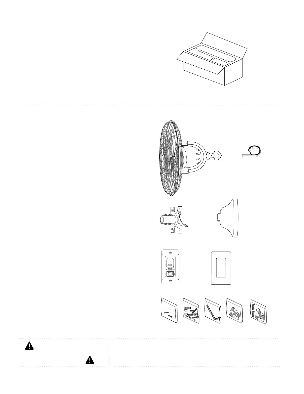
For parts and information,please refer to
"Parts Inventory" on page 3.
Craftmade Customer Support:
1-800-486-4892
www.craftmade.com
Problem: Fan fails to operate.
Solutions:
1.Check power to wall switch.
2.Check to be sure wall control is wired
properly.
3.Verify that slider switch on wall control is set
on High ( ),Medium ( ) or Low ( ) speed.
4.Verify connections from the fan to the wall
are connected properly.
Problem: Fan fails to oscillate.
Solutions:
1.Check power to wall switch.
2.Verify that button on wall control is set to
the ON position.
Problem:Fan wobbles.
Solutions:
1. Check that wall bracket is secure.
2. Check to be sure that fan is securely
mounted on wall bracket.
Warranty.
Parts, Replacement or
Technical Assistance.
CRAFTMADE LIMITED LIFETIME WARRANTY:
CRAFTMADE warrants this fan for use as intended under
the following provision: CRAFTMADE will replace any
fan which has faulty performance due to a defect in
material or workmanship or fails to operate satisfactorily
when failure results from normal use. Contact Craftmade
Customer Service at 1-800-486-4892, Option 1 or via
In the event a product is no longer available,
CRAFTMADE will make best eorts to oer a
comparable product or credit towards another
CRAFTMADE fan.
The purchaser shall be responsible for all costs
incurred in the removal and reinstallation.
This warranty does not apply when damage from
mechanical, physical, electrical or water abuse results in
causing the malfunction. Deterioration of nishes or
other parts due to time or exposure to salt air is
specically exempted under this warranty. Shades and
light bulbs are not covered by this warranty but will be
replaced if found broken at time of purchase.
Neither CRAFTMADE nor the manufacturer will assume
any liability resulting from improper installation or use
of this product. In no case shall the company be liable
for any consequential damages for breach of this, or any
other warranty expressed or implied whatsoever. This
limitation as to consequential damages shall not apply
in states where prohibited.
For parts, replacement, technical assistance or
additional information, please have the fan
model number, name or picture available and
contact Craftmade in one of the following ways:
Customer Support:
1-800-486-4892, Option 1
Technical Support:
1-800-486-4892, Option 2
Email:
customerservice@craftmade.com
www.craftmade.com
Table of contents
Popular Bathroom Fixture manuals by other brands

CAHABA
CAHABA JUNIPER CA101011 manual

Pfister
Pfister Portola RT6-4RP Quick installation guide

Hans Grohe
Hans Grohe PuraVida 15447 Series Instructions for use/assembly instructions

Symmons
Symmons Elm Trim Series Operation & maintenance manual

Lefroy Brooks
Lefroy Brooks M2-4301 Installation, operating, & maintenance instructions

Whirlpool
Whirlpool Ariel HW 123 user manual

Woodbridge
Woodbridge BID 01 instruction manual

Spectrum Brands
Spectrum Brands Pfister LG42-ELT Quick installation guide

Kohler
Kohler URBANITY 25717T-9 installation instructions

Mira
Mira Extreme Thermostatic Installation & user guide

KEUCO
KEUCO Royal Lumos 14307 171351 Instructions for use

KEUCO
KEUCO Plan 14956 Instructions for use