Cramer CBC User manual

T.Nr. 40284
Operating and Installation Instructions for
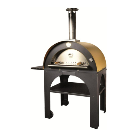
CRAMER Baking Oven
Model CBC
versions CBCG (with grill) and CBCO (without grill)
GB
GB, IE, IS
Product-ID-Number
CE-0085BN0171

2
Important warnings
This appliance of class 3 is designed to be built in a kitchen block.
This appliance is produced in two versions (with and without grill):
1. Oven with grill version CBCG (door down hinged)
Model description See schene of installation
Oven with grill, without chimney, front flue of waste gas Page 7, Fig. 3
Oven with grill, with chimney horizontal – vertical Page 7, Fig. 4
Oven with grill, with chimney vertical and box for waste gas Page 8, Fig. 5
Oven with grill, with chimney horizontal and box for waste gas Page 8, Fig. 6
Oven output (Hs) 1,2 kW (Mn = 85 g/h, propane/butane)
Grill output (Hs) 1,6 kW (Mn = 115 g/h, propane/butane)
(It is technically ensured that both parts cannot be switched on at the same time).
2. Oven without grill version CBCO (door down hinged)
Model description See scheme of installation
Oven without grill, without chimney, front flue of waste gas Page 7, Fig. 3
Oven without grill, with chimney horizontal – vertical Page 7, Fig. 4
Oven without grill, with chimney vertical and box for waste gas Page 8, Fig. 5
Oven without grill, with chimney horizontal and box for waste gas Page 8, Fig. 6
2. Oven without grill version CBCO (door hinged on the left side)
Model description See scheme of installation
Oven without grill, without chimney, front flue of waste gas Page 7, Fig. 3
Oven without grill, with chimney horizontal – vertical Page 7, Fig. 4
Oven without grill, with chimney vertical and box for waste gas Page 8, Fig. 5
Oven without grill, with chimney horizontal and box for waste gas Page 8, Fig. 6
Oven output (Hs) 1,2 kW (Mn = 85 g/h, propane/butane)
If the gas tap is scarcely moving or seizing it is necessary either to replace it or to disassemble
the appropriate tap cone, to clean it with benzoline, to grease it with a special lubricant for taps,
for example one produced by Klüber, Munich, type „Staburgas No 32“ and to assemble it. This
work may be carried out only by a gas specialist.
The appliance may be installed by a qualified person only!
Before installing the appliance it is necessary to check whether local connection conditions (kind
and pressure of gas) are in accordance with appliance settings. Appliance settings values are
shown on the instruction label (on the appliance plate).
This appliance has to be installed and connected in accordance with the valid installation
conditions. Special attention has to be paid to the measures for sufficient ventilation.
Gas supplying parts and waste gas connected lines (waste gas pipe) have to be tested by
specialist according to valid norms before the initial operation and every two years thereafter.

3
The user is responsible for arranging the test. The installer of the appliance has to inform in
writing the user about this compulsory test.
The appliance can be only used for baking and grilling under conditions mentioned hereinafter. It
must not be used for other purposes than described in this manual (e.g. heating, etc.).
Use of the appliance can cause creation of warmth and/or humidity in the room, where it is
placed. It is necessary to supervise the ventilation of the kitchen: natural venting air-openings or
mechanical ventilations.
Intensive and longstanding use of appliance may require auxiliary ventilation, for example
opening of a window or run of a ventilation device at a higher performance level.
Pressure reducers between gas cylinder and appliance have to respond to categories as follows:
Category mbar Gas Output pressure reducer
G 30 (Butane) 1,5 Kg/h
I 3 (50) 50 G 31 (Propane) 1,5 Kg/h
I 3+ (28-30/37) 28-30
I 3 (30) 30 G 30 (Butane) 1,5 Kg/h
I 3+ (28-30/37) 37
I 3 (30) 30 G 31 (Propane) 1,5 Kg/h
ATTENTION: THE APPLIANCE HAS TO BE INSTALLED BY A SPECIALIST IN
ACCORDANCE WITH THE VALID NORMS.
IMPORTANT: IN ORDER TO PREVENT ANY ACCIDENT IT IS NECESSARY TO
INSTALL THE APPLIANCE IN ACCORDANCE WITH THE PRESENTED
INSTRUCTIONS. UNQUALIFIED INSTALLATION CAN RESULT IN THE LOSS OF
GUARANTEE.
„EACH MODIFICATION OF THE APPLIANCE CAN BE DANGEROUS!“
1. VENTILATION OF THE ROOM
Each room, where one or more appliances are intended to be installed, has to be equipped
with one or more openings allowing input of fresh air with a minimum total available cross-
section 100 cm2. These openings may be situated at various points of the room, have to be
placed near the floor at a height of maximum 10 cm above the floor.
One or more openings with a minimum cross-section 150 cm2have to be placed above the
appliance.

4
These openings have to be from time to time checked and/or cleaned by the user (e.g. clean
the waste-gas output from snow and the combustion air inlet from melting snow in winter).
The opening of the waste gas outlet must not be placed at the entry door and under
ventilation openings.
If waste gas is discharged through the roof it is necessary to check whether the waste gas line
is installed in the upward position.
2. CONNECTING THE APPLIANCE TO THE GAS SUPPLY
Connecting the appliance to the gas supply can be only executed using gas-tight connector or
standardised tubing connection (max. length 1.5 metres), which have to be replaced before
their expiration date.
When laying rubber tubings it is necessary to make sure that they do not touch metal parts,
which become extremely hot during the use of appliance, e.g. ones under the burners.
When using pipes to connect the appliance they have to be made of galvanised iron or
copper. These pipes have to be used with a gas-tight connector. After completion of the gas
connections the gas lines has to be tested for gas leakage by applying soapy water over
connection points and gas lines; gas leaks will show up as bubbles where the gas leak occurs.
ATTENTION: DURING INSTALLATION AND CONNECTION OF APPLIANCE
THE GAS PIPE CANNOT BE TURNED, PULLED OR IN A DIFFERENT WAY
STRAINED.
3. GAS CYLINDERS
Gas cylinders usually used in the country where the appliance was sold have to be used. The
usable gastype is clearly definied on the package and on the wipe resistant label on the
backside of the appliance.
USE OF PRESSURE OR GAS DIFFERENT FROM INSTRUCTIONS CAN CAUSE
AN UNSTABLE RUNNING CONDITIONS OF THE APPLIANCE; THEREFORE
THE PRODUCER REFUSES ANY RESPONSIBILITY CONCERNING THE
CONNECTION WITH UNQUALIFIED HANDLING OF THE APPLIANCE.
In any case the following instruction have to be followed:
Gas cylinders with tap and pressure reducer have to be positioned in vertical position in
a case intended for this purpose. Input of cylinders must not be obstructed.
Replacement of the gas cylinder has to be fluent and without any difficulties.
AFTER USE THE GAS CYLINDER HAS TO BE ENCLOSED

5
ATTENTION!
When replacing a gas cylinder the following safety measures have to be carried out:
a) Close the taps on the appliance (turn the knob into position 0);
b) Make sure that no flame or flaming articles are located close to it;
c) Close the tap of the cylinder being replaced;
d) Unscrew the pressure reducer from the empty cylinder, take the last one out of the
case and replace it with a new gas cylinder – when connecting a new gas cylinder
proceed in the reverse sequence.
Test theleakage by applying of soapy water in the above mentioned way.
e) Fire up the burner and check the proper run; otherwise refer to a specialised
technician.
3.1 CASE FOR GAS CYLINDERS
The case for gas cylinders has to be spacious enough for the intended type of cylinder with
installed pressure regulator.
4. VISUAL CONTROL OF FLAME
a) The flame has to burn still. It has to be predominantly blue coloured and with clear
contours.
b) If the flame does not burn steady, it is necessary to check whether air inlet openings
(Venturi tube) are free of obstacles. Otherwise the obstacles have to be removed.
5. POWER SUPPLY AND ELECTRICAL CONNECTION:
The electronic ignition of the grill and oven burners requires a 12 V DC power supply.
ELECTRICAL CONNECTION
To connect the appliance a twin core, 1,5 mm2red and black cable shall be used and
connected to the terminal board on the back of the appliance. This terminal board has both
poles marked with + and -. The + pole is to be identified with the red colour cable. When
connecting the cables it is absolutely necessary to observe the right polarity! The electric
circuit has to be protected against fusion with a 3 A fuse (not supplied with the appliance).

6
Min15m m
7m m
Max30m m
UNDER NO CIRCUMSTANCES MUST THE APPLIANCE BE CONNECTED TO 220
V POWER SUPPLY! IT MAY CAUSE TOTAL DAMAGE OF ELECTRICAL
COMPONENTS AND DANGER FOR USERS.
6. GAS LEAKAGE
To check gas leakage we recommend to use an electric gas detector of a verified type. In
case of an accident close the gas inlet tap and refer to a gas-fitter, seller or specialised
technician.
7. FIXATION OF THE APPLIANCE TO FURNITURE
To build the appliance ino furniture a space with dimensions shown on fig. 1 - 6 must be
available depending to model (see label of appliance). Arbitrary position can be chosen.
The appliance has to be placed on a firm, stable base in furniture. The front of the appliance
must be fixed firmly to the furniture by means of supplied screws and 4 mounting frames.
For fixation it is not allowed to use gas lines, taps or parts of burners.
Fig 1
Fig 2
C
Fixation to furniture
Furniture
Detail D
Oven
D
SECTION A-A

7
Fig 3 Installation of oven without chimney, front flue of waste gas.
Fig 4 Installation of oven with chimney horizontal – vertical.
Minimum distamce from combustible
areas backward and towards right and
left sides: 20 mm.
Minimum distance from combustible
areas upward: 50 mm.
Section: the front side horizontally
with building in (see installation
drawing No. 39986)
Minimum distamce from
combustible areas backward and
towards right and left sides: 20 mm.
Minimum distance from combustible
areas upward: 50 mm.
Section: the front side horizontally
with building in (see installation
drawing No. 39986)

8
Fig 5 Installation of ovens with chimney vertical and with box for waste gas.
Fig. 6 Installation of ovens with chimney horizontal and with box for waste gas.
Minimum distamce from
combustible areas backward and
towards right and left sides:
20 mm.
Minimum distance from
combustible areas upward: 50 mm.
Minimum distance of waste gas
line box from combustible areas:
50 mm
Section: the front side horizontally
with building in (see installation
drawing No. 39986)
Section: the front side horizontally
with building in ( see installation
drawing No. 39986)
Minimum distance from combustible
areas backward and towards right and
left sides: 20 mm.
Minimum distance from combustible
areas upward: 50 mm.
Minimum distance of waste gas line
box from combustible areas: 50 mm

9
ATTENTION: Installation of baking oven with chimney horizontal is allowed only with the
waste gas line box, partnumber 43661 (new version ) and without chimney-adapter.
ATTENTION: For the reason of saving of weight the oven for an OEM (producer of
caravans or motorhomes) might be also delivered without the outer housing.
The waste gas line through chimney pipe has to be in upward position. Maximum length of the
waste gas line is 2.000 mm. The maximum elevation difference between the upper edge of oven
and the point of waste gas outlet from the chimney is 1.500 mm.
Walls and components closer than 50 mm to the waste gas exhaust have to be wrapped or
protected with materials belonging to M0 fire-resistant group.
Ø 50 mm flexible pipe of the waste gas exhaust made of a high-grade steel has always to be
fixed at the outlet from the oven and at the inlet to the chimney adapter by means of one strap
with a screw thread Ø 50 - Ø 60 mm (Truma´s thread appertaining to the pipe).
7.1 THE APPLIANCE HAS TO BE INSTALLED IN A SAFE DISTANCE FROM
INFLAMMABLE MATERIALS.
7.2 PROTECTION AGAINST OVERHEATING
All walls or components which are closer to the appliance than the minimum distance in the
drawing (see Figures 3 - 6) have to be wrapped or protected with materials belonging to M0
fire-resistant group.
7.3 REMOVAL OF THE APPLIANCE FROM FURNITURE
a) Close the main gas tap
b) Release fastening screws
c) Disconnect gas adapter and/or electrical cables.
8. USE THE APPLIANCE ONLY IN A SUFFICIENTLY VENTED ROOM
If the appliance is being used, venting openings shall to be without obstructions.

10
GRILL
Front edge
Pan
Back edge
9. USE OF THE APPLIANCE
9.1 IGNITION OF THE APPLIANCE
AUTOMATIC IGNITION: OVEN – GRILL
a) To ignite the oven or grill the oven door has to be completely open.
b) Push the knob gently and turn into the ignition position. Getting the oven into
operation is possible in all positions 1-6 of the knob (after pushing turn the knob to the
left). Getting the grill into operation (for ovens with grill only) is possible if the knob
is in the position Grill (after pushing and turning the knob to the right).
c) Release the knob and turn into the chosen position.
Notice: When operating the grill the sheet protecting against heat has to be completely drawn
out (see 9.3a too).
Various positions of the knob correspond approximately to the following temperatures of the
oven (in oC)
POSITION 1 2 3 4 5 6
TEMPERATURE 140 170 190 210 230 250
If an excessive deviation of the oven temperatures is experienced it may be necessary to
repair or replace the thermostat.
IMPORTANT: If the ignition of the burner is not successful at the first attempt, repeat the
process from the beginning. If necessary, check the gas or current supply to the appliance. If
the appliance does not work in spite of all that, close the gas inlet tap and refer to your seller.
Before the initial operation of the oven, let it run empty (without food) for app. ½ hour at the
maximum temperature. If the flame of burner blows out mistakenly, close the burner
regulator and before repeating the ignition of the burner let it extinct for minimum 1 minute.
„IT IS A SAFETY REQUIREMENT THAT OVEN GLOVES ARE USED WHEN
HANDLING THE HOT OVEN TRAY OR ROTISSERIE. “
9.2. USING THE OVEN
a) The pan has to be inserted in the oven so that the
perforated (front) edge is at the front
GRILL

11
Sheet protecting against heat
Position of the door during grilling
b) The pan has 3 optional levels.
Notice: When grilling using the rotisserie the pan has to be in the position „1“..
c) The grill shelf can be turned, thus allowing 2 levels
9.3. Handling of the grill (only for appliances with grill).
a) The heat protecting sheet must be pulled out as far as possible during grilling.
b) To ignite the grill burner the oven door must be completely open.
c) When operating the grill the oven door has to be half-open.

12
ATTENTION: When operating the grill the appliance reaches high temperatures.
Keep children away.
9.3.1. USING THE ROTISSERIE (only for appliances with grill).
a) Place the pan with the assembled left-hand holder of the rotisserie in the oven.
Insert the rotisserie ino the the grill motor shaft hole. Insert the left side of the
rotisserie into the rack holder. Switch on the rotisserie motor by means of the
switch for this purpose.
b) When grilling using the rotisserie the pan has to be in the position „1“ (see 9.2.a).
10. FAILURES OF THE APPLIANCE
In the event of failure of the appliance please contact the dealer you purchassed the
appliance from or the distributor.
11. CLEANING INSTRUCTIONS
The appliance needs little maintenance other than cleaning. To clean the appliance use
only warm soapy water and recommended household cleaning agents. Do not use
abrasive cleaners, steel wool or cleansing powders.
CRAMER SR s. r. o.
●Tehelná 8 ●SK – 986 01 Fiľakovo ●Telephone: +421-47-4319100 ●
●Fax: +421-47-4319133, 4319166 ●
●E-mail: cram[email protected] ●
●Internet: www.cramer.sk ●
Left-hand holder of the
grill rack
Insert into the grill motor shaft
07/2004
Table of contents

