Crane IQWrench2 Opta User manual

IQWrench2 OptaOpta
OptaOpta
Opta
Digital Torque Wrench
Operator’s Manual
Manual 1181: Issue 2a
Crane Electronics Ltd
NOTICE
ALL RIGHTS RESERVED. Reproduction of any part of this manual in any form whatsoever,
without the prior permission in writing from Crane Electronics Ltd is forbidden.
Copyright © May 2013 by Crane Electronics Ltd
The contents of this manual are subject to change without prior notice.
ATTENTION - BATTERYCHARGING
The IQWrench2 Opta is powered by a Lithium Polymer battery. This battery must be charged by
placing the wrench into its cradle.
PLACING TOOL IN SERVICE
Always operate, inspect and maintain this unit in accordance with all regulations (local, state,
federal and country) that may apply.
Do not remove any labels.
USING THE TOOL
Always use Personal Protective Equipment appropriate to the tool used and material worked.
Keep body stance balanced and firm. Do not overreach when operating this tool. Anticipate and be
alert for sudden changes in motion, reaction torque, or forces during the operation.
Ensure work pieces are secure. Use clamps or vices to hold work piece whenever possible.
Never use a damaged or malfunctioning tool or accessory.
Maintain unit with care. Keep unit clean for better and safer performance. Follow instructions for
changing accessories.
Do not operate this product in explosive atmospheres, such as in the presence of flammable
liquids, gases or dust.
Do not modify this product for purposes other than those recommended.

2
IQWrench2 Opta
CE MARKING
Manufacturer: Crane Electronics Ltd
Address: Watling Drive
Sketchley Meadows
Hinckley
Leicestershire
LE10 3EY
United Kingdom
Tel: +44 (0)1455 251488
Declares that this product has been assessed and complies with the requirements of
the relevant CE Directives
Caution: Changes or modifications to the IQWrench2 Opta not expressly
approved by Crane Electronics Ltd could void the user’s authority to operate
the equipment.

3
IQWrench2 Opta
CONTENTS PAGE
SECTION 1 Introduction ..................................................................................................... 4
How to use this manual ........................................................................................... 4
Packing List ............................................................................................................. 4
Care and Storage .................................................................................................... 4
Overview .................................................................................................................. 5
Batteries .................................................................................................................. 7
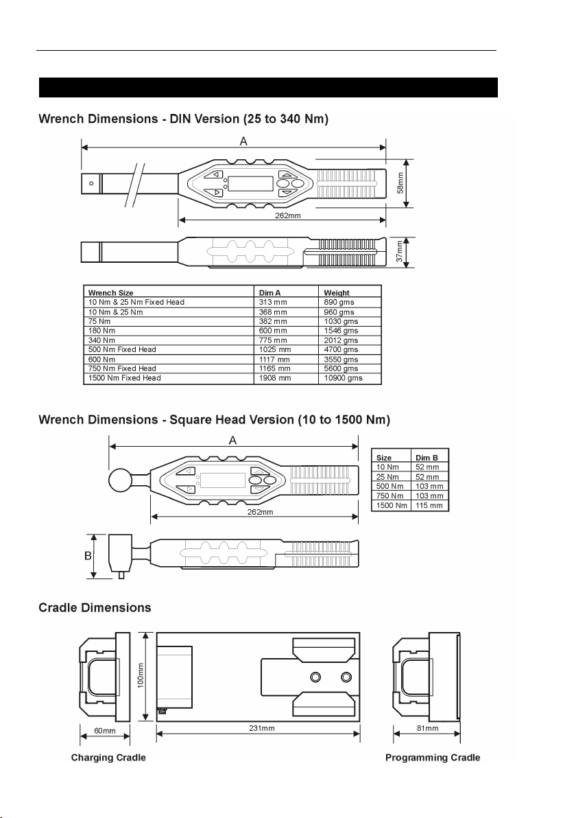
Dimensions .............................................................................................................. 8
Specifications ........................................................................................................... 9
Accessories ............................................................................................................. 9
SECTION 2 Controls ......................................................................................................... 10
Removing & Attaching Drive Adaptors ................................................................... 10
Control Panel ......................................................................................................... 11
Charging/Comms Cradle ....................................................................................... 12
SECTION 3 Operating Instructions .................................................................................. 13
Charging the Wrench ............................................................................................. 13
Basic Operation ..................................................................................................... 14
Powering On .......................................................................................................... 14
Auto Power Off...................................................................................................... 14
Hardware Reset ..................................................................................................... 14
Attaching a PC ....................................................................................................... 14
Basic Operating principles ..................................................................................... 15
Basic Menu Structure ............................................................................................. 17
Getting Started - Using for the first time ................................................................. 18
Changing the Time and Date and Date Format ..................................................... 18
Changing the Language ........................................................................................ 18
Taking a Reading - Quick Read Mode ................................................................... 19
Taking a Reading - Quick Store Mode ................................................................... 22
Quick Read setup Menu ....................................................................................... 28
Quick Store Setup Menu ........................................................................................ 29
Main Setup Menu ................................................................................................... 32
Power Settings Menu ............................................................................................. 33
Battery Charge Indicator ........................................................................................ 34
Advanced Operation ......................................................................................................... 35
Features (Advanced Mode) ................................................................................... 35
Using with Opta Comms ........................................................................................ 36
Working with Jobs ................................................................................................. 36
Working with Rounds ............................................................................................. 40
Remote Setup ........................................................................................................ 41
Comms Setup ........................................................................................................ 41
Flash Program ....................................................................................................... 41
Software Reset ...................................................................................................... 41
Trace Duration ....................................................................................................... 44
Verification and Adjustment ................................................................................... 44
Zero Gyro ............................................................................................................... 44
Section 4 Additional information and features ............................................................... 45
Gyro ....................................................................................................................... 45
Cycle End Time ..................................................................................................... 45
LEDs ...................................................................................................................... 46
Regional Settings .................................................................................................. 46
Buzzer ................................................................................................................... 47
Remote Setup ........................................................................................................ 47
Remote Protocol .................................................................................................... 48
Status Bar .............................................................................................................. 48
Power .................................................................................................................... 49
Wireless ................................................................................................................ 51
Change Rv ID ........................................................................................................ 51
Retry Function ....................................................................................................... 52
Users ..................................................................................................................... 53
ID Adapter .............................................................................................................. 54
Calibration Date ..................................................................................................... 54
Measurement Modes ............................................................................................. 55
Job Measurement Icons ........................................................................................ 56
Yield Function ........................................................................................................ 57
Specialist Job Function .......................................................................................... 60
Downloading Jobs ................................................................................................. 61
Glossary of Terms .................................................................................................. 62

4
INTRODUCTION Section 1
HOW TO USE THIS MANUAL
This manual is split into sections describing the steps to be taken to configure the
IQWrench2 Opta for use in measuring and recording torque values.
Section 1 is an introduction to the IQWrench2 Opta.
Section 2 describes the controls and features.
Section 3 describes how to configure and use the IQWrench2 Opta .
Section 4 gives additional information on certain features.
The following conventions are adopted throughout this manual:
Keys to be pressed will be shown as the key legend - for example Enter
Information displayed on the LCD screen will be shown in italics contained within
quotation marks i.e. ‘Select Fault’ or displayed as an actual screenshot.
PACKING LIST
The following items are supplied with the Basic and Production IQWrench2 Opta
units.
1x IQWrench2 Opta Digital Torque Wrench
1x Charging Cradle unit
1x PSU
1x Mains cable
1x Opta Comms software (+ USB driver)
Additional items supplied with Advanced IQWrench2 Opta
1x Programming Cradle (instead of a Charging Cradle)
1x USB cable
CARE & STORAGE
This unit is designed for indoor use only
Operating temperature range 5-40 degrees C
Storage temperature range 0-50 degrees C
The membrane keypad may be wiped clean with a soft damp cloth.
THIS UNIT CONTAINS NO USER SERVICEABLE PARTS. ONLYQUALIFIED
SERVICE PERSONNEL SHOULD REPLACE OR FIT PARTS.

5
INTRODUCTION Section 1
OVERVIEW
IQWrench2 Opta combines all the features of a high specification digital torque and angle
wrench with a data collection system in one ergonomic package.
The IQWrench2 Opta is a powerful, smart torque tool which is essential in both the Quality
Audit and Assembly environments. This rugged, but light tool can be used on a stand alone
basis or as part of a sophisticated production control system.
Depending on customer needs, the IQWrench2 Opta can be configured as either a basic tool
or an advanced data collection system. Flexibility is enhanced as the software in the
IQWrench2 Opta can be upgraded almost as soon as a change is required.
The IQWrench2 Opta features the following four measurement modes, Track, Peak , Audit
and Yield. All of the above modes, other than Track, when the options are enabled, have
the facility to set specification and control limits. This enables the wrench to give the user
information as to the status of the torque cycle. This information is displayed in 4 ways:
On screen
As multi colour LEDs (on the top and underside of the wrench)
As a buzzer
As a vibrating handle
These indicate a HI, LO or OK fastener status and are known as the “Fastener Status
Indicators”.

6
INTRODUCTION Section 1
Track
This is the display of real time torque and it is typically used when calibrating the
IQWrench2.
Peak
In this mode the wrench can be used to audit the residual values of a pre-
tightened fixing or used as a tightening tool for low volume tightening applications.
The wrench can be set-up and used in 4 different ways:
Peak only
In this mode the wrench displays torque and the fastener status indicators are
activated when the control and specification parameters are reached.
Peak with Torque control
In this mode the wrench displays torque and angle, however, the fastener status
indicators are still activated on the Torque control and specification parameters
being reached. The wrench also uses a second parameter which is angle; this
angle information is used to monitor an angle window, giving greater security to
the tightened fixing.
Peak with Angle Control
In this mode the wrench displays torque and angle, and now uses the second
parameter of angle as the controlling parameter. The fastener status indicators
are now activated when the Angle control and specification parameters are
reached. The wrench is now operating as a production tool that is tightening to a
“pre” torque and final angle window.
Yield
In this mode, the wrench uses Torque and Angle to detect when the joint being
tightened is going to yield. The torque and angle values at this pont are
displayed and stored. The yield point is where the torque vs angle curve
gradient reduces to half its maximum value.
Audit
In this mode the wrench is purely used for auditing a pre-tightened fixing. This is a
special software algorithm that senses the break away point of the tightened fixing
and displays the torque value after a defined number of degrees is reached. In this
mode the wrench displays torque and the fastener status indicators show if the
correct angle has been pulled. The wrench will also display the final peak torque -
achieved once the cycle is complete.

7
INTRODUCTION Section 1
The IQWrench2 Opta is designed to be point of load insensitive, which means that the
operator can be assured of correct measurement, however the wrench is held and
torque is applied - particularly useful in limited access situations.
The IQWrench2 Opta can read the ID of special adaptors. It can use the ID and
check its value in a table loaded into the wrench to compensate for different length
adaptors. The wrench software can force a specific adaptor ID to be used for a
specific job, and to choose a specific job that uses that specific adaptor.
The IQWrench2 Opta is supplied with DIN standard interchangeable head fittings,
giving a wide range of head attachments to meet the assembly requirements, or a
fixed square head – dependent on torque range. There is an adaptor that will convert
the DIN heads to Dovetail (Sturtevant Richmond) which allows dovetail attachments to
be used.
When used in Jobs mode, the IQWrench2 Opta has the ability to store a large amount
of date and time stamped readings for each of the fasteners audited. This data can be
uploaded and stored on the PC with the use of the Opta Comms or OMS platform.
Data from the IQWrench2 Opta can be uploaded to a PC using a USB cable. The
IQWrench2 Opta has to be on a programming cradle to communicate to a PC via a
cable.
BATTERIES
IQWrench2 Opta uses a 3.7V Li Polymer battery (battery life - 14 hours of typical
use). It is recommended that the battery is replaced after 2 years of normal (single
shift) use, or 1 year of heavy (double shift) use during calibration / service.
Battery Disposal
To be disposed of in an environmentally sound manner and in
accordance with local legislation.
Do not incinerate.
Do not disassemble.
Do not short the terminals or expose to high temperatures.
Where the customer has issues disposing of batteries - please return to Crane
Electronics.
It is an offence to throw portable batteries out with domestic refuse.

8
INTRODUCTION Section 1
DIMENSIONS

9
INTRODUCTION Section 1
SPECIFICATIONS
Power: One Li Polymer 3.7V battery - 2000 mAh capacity
Accuracy: ±0.5% of rated maximum wrench capacity.
Overload Capacity: 125% of stated maximum wrench capacity.
Zero Drift: <0.1% of rated maximum wrench capacity.
Operating Temperature
Range: +5 to +40 degrees Celsius
Temperature Stability: ±0.1% per degree Celsius.
Sealing: IP40.
Humidity: 5% to 75% non condensing.
Calibration: Issued with calibration certificate traceable to national
and international standards. 12 months typical
recalibration interval.
Warranty: 12 months parts and labour.
Servicing: Crane Electronics Ltd offer a repair facility and
calibration to UKAS and international standards.
Crane Electronics Inc. operates a calibration
laboratory with a Certificate of Accreditation to ISO/
IEC 17025, and a certificate of compliance to ISO
9001. Reference standards are traceable to N.I.S.T.
standards.
ACCESSORIES
ITEM PART No.
RS232 Cable 090184
USB cable 090260
Programming Cradle IQW2S-0000-CRCPUX
Charging Cradle IQW2S-0000-CRCCXX
PSU for cradle 080154
Adapter heads with ID Contact Crane

10
CONTROLS Section 2
CONTROLS
REMOVING AND ATTACHING THE DRIVE ADAPTORS
DIN Standard Head
The DIN adaptors simply push into the rectangular slot at the end of the head as
shown. Press the locking pin to allow the adaptor to click into position.
Press the release button on the underside of the wrench shaft and pull the adaptor to
remove.
SR (Sturtevant Richmont) Head (attached to DIN to SR adaptor)
To remove a SR head, insert a small screwdriver into the access hole as shown,
depress the small locking pin and slide the adaptor to the side - see below.
To attach a drive adaptor, depress the locking pin and slide the adaptor into place
until it locates with a click.
Rear of Wrench

11
CONTROLS Section 2
CONTROL PANEL
ENTER KEY (green)
Used for confirming a selection or accepting an option etc. Similar to the
Return key on a computer.
ESCAPE KEY (red)
Used for cancelling an option.
UP/DOWN ARROW KEYS
Used to toggle between screens and options (small arrows on right of screen
show direction(s) available).
LEFT RIGHT ARROW KEYS
Used to select different fields or options.
All the functionality of the wrench is accessed through a simple menu structure with
the aid of the 4 arrow keys, the ENTER Key (Green) and the ESCAPE Key (Red).
Ashort single press is sufficient to operate the keys.
A click will be felt when the keys are operated.
keys are used to navigate through the menus on the same level.
Pressing ENTER on a displayed menu function will take you into the relevant
menus for that function.
Pressing ESCAPE will take you up a level back towards the main menu
(except when in the ‘ABOUT’ screen).
If you keep pressing the keys you will go through all the menus on that level and
will return to where you started. When you choose a menu item, the IQWrench2 Opta
will remember which sub-menu item you chose last time.

12
CONTROLS Section 2
CHARGING/PROGRAMMING CRADLE
Cradle Connections (example shown is a programming cradle)

13
OPERATING INSTRUCTIONS Section 3
CHARGING THE WRENCH
Replacing Battery
It is recommended that the battery is replaced after 500 uses/1 year of heavy use, or
after 2 years of light use during service / calibration.
Charging
The following information assumes battery info is set to ‘ON’ in Setup
NOTE: Before placing in the cradle, wrench must be switched on and in a measure
mode ready to accept readings .

14
OPERATING INSTRUCTIONS Section 3
POWERING ON
To switch on the IQWrench2 Opta, press any arrow key.
If the wrench is switched on after it has powered down, it will return to the menu/
screen it was in before power was removed, or to the User menu if power was lost in
a Jobs/Rounds menu. You will see ‘Initialising...’ and ‘Wait...’ messages as the unit
powers up.
HARDWARE RESET
To perform a hardware reset, press the (RIGHT) and (UP) keys together.
Note: Performing a Hardware Reset resets the IQWrench2 Opta but does not erase
any settings or Job information. See Power in Section 4 for more information.
AUTO POWER OFF FUNCTION
As an energy saving feature, the IQWrench2 Opta is programmed to power down
automatically if it has received no user input for a predefined period (10 mins is the
default setting, but can be set to 1 minute as a minimum, through to constant power
on). Pressing any key will restore the unit to the last display prior to powering off. This
is to avoid the possibility of loss of data due to an interruption to the operator’s
activities while using the IQWrench2 Opta.
To Switch off without waiting for the Auto Power Off, go into Main Menu, scroll down
to the Power Off Icon (showing the symbol) and press ENTER.
ATTACHING A PC
Data from the IQWrench2 Opta can be downloaded to a PC by placing the wrench in its
programming cradle and connecting the cradle to the PC using the USB or RS232 cable
(see page 12).

15
OPERATING INSTRUCTIONS Section 3
BASIC OPERATING PRINCIPLES
MAIN MENU
This menu allows the user to choose between the following items:
Quick Read - Enter the Quick Read mode
Quick Store - Enter the Quick Store mode
Jobs (advanced model only) - Needs jobs loaded from Opta Comms
Rounds (advanced model only) -
Needs Rounds loaded from Opta Comms
Comms (advanced model only) - Communications via cradle
Remote Setup (advanced model only) - Through wireless or serial port
Setup - Enter the Setup menu (see below)
Logout (advanced model only) - Logout manually as user (see Jobs)
Power Off - Switch off manually
Zero Gyro - Wrench sets zero angular velocity
The screen shows only one menu item at a time. To navigate the menu, use the
cursor keys to scroll, and then press ENTER to select as shown below:
1 2

16
OPERATING INSTRUCTIONS Section 3
SET UP MENU
This menu allows the setup of following parameters:
Date & Time - Setup the date & time and their formats.
Regional Settings - Change the language and the decimal point.
Power Settings - View battery status, change the power setting parameters and switch off.
Buzzer- Set the audible buzzer, vibrator and targetting functions.
LED Setup- Set what LEDs do at beginning, during and at end of measurement cycle.
Printer Setup - Set the column width, specialist Jobs functions and Autoprint enhance.
Auto Print Setup - Lets you change format of what values are printed.
Display Setup - Sets the full Job Name to be displayed or not, adaptor ID warnings & functionality,
and flash LEDs on errors.
Sequence Setup - set Comment, Barcode, Preload and Gyro, speed.
Trace - Set the trace duration, storage of multiple trace and real-time trace to PC.
Comms Setup (Wireless feature enabled) - Select between cable, bluetooth and RF for external
communications, Protocol Setup and RF Comms.
Restore App. Data - Perform a software reset . This should normally be used after hardware
reset. Note: Allows restore of Jobs / Rounds / Users / ID Table.
Flash Program - Flash download to update software
About - Displays the product name,software version number, span, serial number and calibration
due date
Features - Displays the list of enabled features and gives the operator the option
to enter an upgrade activation code if purchased from Crane.
Verification and Adjustment - Verification and Adjustment of calibration (password required from
Crane Electronics). User can set up own calibration date.
Display Contrast - Alters the colour contrast of the screen LCD (default = 128)
User Type - Set Limited/Normal user access (use with specialist job function).
Trigger - Enable/disable trigger (only in Quick Read).
Bolt Overtighten - RFU.
Retry Function - Set number of attempts to get OK reading in Jobs.
Job Selection - Allows adaptor ID to select job and how long loaded job is valid.
First In - First Out - No limit on number of readings taken. Remembers last N readings.
Settings - Allow wrench settings to be read and written.

17
OPERATING INSTRUCTIONS Section 3
BASIC MENU STRUCTURE
The diagram below shows the basic menu structure of the IQWrench2 Opta.
Use the keys until the required screen is displayed and press ENTER.
Note: There is a short beep when wrapping round from end of menu to beginning or vice
versa.
Note: items shown in italics will be greyed out and inaccessible if those features have not
been enabled - contact Crane for more details.

18
OPERATING INSTRUCTIONS Section 3
GETTING STARTED - USING FOR THE FIRST TIME
Setting the Time and Date
The Time and Date is set in Main Setup Menu / Time and Date. Use the keys to
scroll to the Time screen and press Enter. Use the keys to change the
hour digits above the cursor and the keys to advance along to the minutes and
then the seconds. When the time is correct, press Enter.
Press ESCAPE to return to the main Setup Menu.
The Real time clock and memory have their own battery backup supply
so will not lose data if the main battery is removed.
Repeat the process for the Date screen changing the digits in the same way until the
correct date is showing.
Changing the Date or Time Format
The format of how Date and Time is to be displayed can be selected.
From the Date and Time Menu, Select Date Format or Time Format and use the
keys to select the required format and press Enter.
Press ESCAPE to return to the main Setup Menu.
Changing the Language
IQWrench2 Opta can display one of several different languages.
These are found in the Main Menu / Main Setup Menu / Regional Settings / Lan-
guage.
Use the keys to select between: English, Deutsch, Francais, Espanol, Italiano,
Swedish, Czech, (Flemish), (Portugues) or Turkce and press Enter to select.
Press ESCAPE to return to the main Setup Menu.
The language can also be changed temporarily during Start up using the ‘Language
at Start’ setting.
Changing the Decimal Point style
There is also an option to change the decimal point in displayed
numbers from a ‘.’ (period) to a ‘,’ (comma), to suit local conventions.
This is found in the Main Menu / Setup Menu / Regional Settings / Decimal Point.
Press ESCAPE to return to the main Setup Menu.
Turning the audible signal (Buzzer) On, Off or Targeting
From the Main Setup Menu, use the keys to scroll to Buzzer menu and press
ENTER. Press and use the keys to select the required setting (On,
Off or Targeting), and press to accept.
Press ESCAPE to return to the main Setup Menu.
See Section 4 - Buzzer for more information.

19
OPERATING INSTRUCTIONS Section 3
GETTING STARTED - TAKING A READING
From the main menu, select the required measure mode. The screen shows just one
item from the menu. Use the Up and Down arrow keys to navigate between screens
and press ENTER to access the required mode. Shown below are the screens
for the 2 measure modes - Quick Read and Quick Store.
Note: Any Items shown greyed out on any of the menus are unavailable at present
and cannot be selected. This is either due to certain features not being activated for
this particular user, or the user has not logged in.
QUICK READ MODE
Quick Read Menu
The following options are available in Quick Read Mode:
Track
Peak
Audit Control (greyed out if wrench does not have angle capability)
Use the keys to scroll between Peak, Track or Audit measurement modes and press
ENTER. Note: Track mode shows a continuous real-time torque read-out, Peak
shows only the peak torque achieved and Audit shows the torque value after a
defined angle of rotation.
QUICK READ SCREEN - PEAK QUICK READ SCREEN - TRACK

20
OPERATING INSTRUCTIONS Section 3
With a suitable drive adaptor and socket in place, connect to the required fastener
and apply torque. Check the read-out in the display.
To change the following parameters:
Memory Used %
Units of Torque Measurement
Direction of Rotation
Cycle End Time
Torque Threshold
2nd Parameter (angle or none)
Angle Torque Threshold (only if Angle set as 2nd param.)
Auto Print
Inhibit Trace To store Trace Inhibit = No
To not store Trace Inhibit = Yes
Adapter Length (for ID fitted if ID table loaded or a manual editable length)
Use the keys to highlight the Setup Icon and press ENTER to
access the Quick Read Setup Menu. See page 28.
To View the selected options, select the icon and hold down ENTER.
For more details, see Quick Read Setup menu info on page 28.
Screen Information For Quick Read Mode
TORQUE PROMINENT
DURATION PROMINENT
The above pictures show the alternative screen display formats - press the
key to toggle between screens.
Table of contents
Other Crane Power Tools manuals
Popular Power Tools manuals by other brands

Black & Decker
Black & Decker BDCD8 Original instructions

King Canada
King Canada KSB-350-LED instruction manual

TE Connectivity
TE Connectivity CBP-5T Mk II Customer's manual

Clarke
Clarke ZX-R Pro Series Operation & maintenance instructions

Makita
Makita DJS160 instruction manual

Hafco
Hafco PD-22 instruction manual