[F]
Barrierephoto-electrique N°,5506 C
..
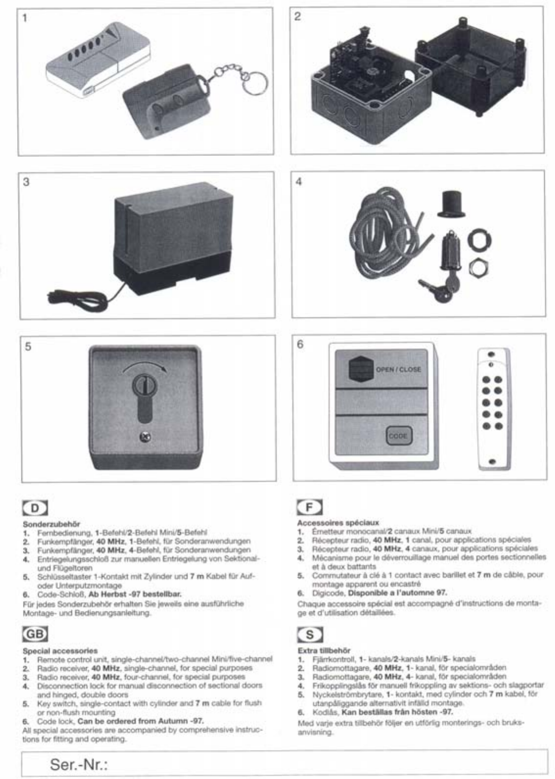
Equipement fourni
. BoTte å relais
. Cellulephotoelectrique
.Cåble
.Plaque de fixation
.Jeu de montage
råcepteur et emitteur
3 x 0,25 mm2,8 m de long
pour montage sur le railde la porte,
speciale pour portails Crawford
et rondellespour la plaque de fixation;
viset ehevillespour la boite å relais
visde fixation,åctrous
plans electrique et de montage
.Instruetions de montage
.Etiqyettes de protection
Instructions de montage
Botteå relais:
.Plaeer la boTte å relais sur le linteau de la porte, au-dessus ou å eate
de I'extremite du rail;se refererau sehema des eonnexions.
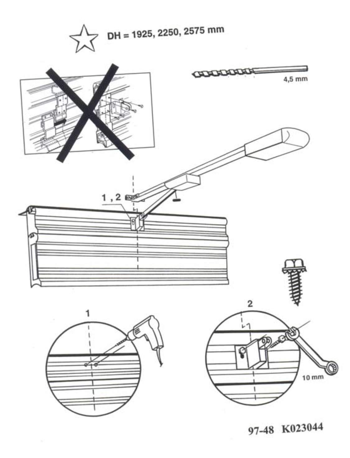
Plaques de fixation:
.Dans ehaque rail de porte, pereer deux trous (ø 6,5 mm)
eorrespondant aux trous de la plaque de fixation.
.ATTENTION! Les plaques de fixation dolivent etre placees de
fayon opposee, å la meme hauteur et avec I'arete superieure il
150 mm, au maximu, au-dessus du niveau du sol. Si on n'utilise
pas de plaques de fixation,on peut utiliserles quatre trous dans la
partie inferieuredu boitierpour lafixationau mur.
.Monterla plaque de fixationsur le railmural,la tete de visdirigee
vers I'interieur.
.Pour les portails Crawford de type PRIVAT,la plaque de fixation doit
etre plaeee å I'exterieursur le eapot du bomier.Veillerå inserer deux
rondelles par trou de fixationentre lecapot du borneier et la plaque
de fixation.
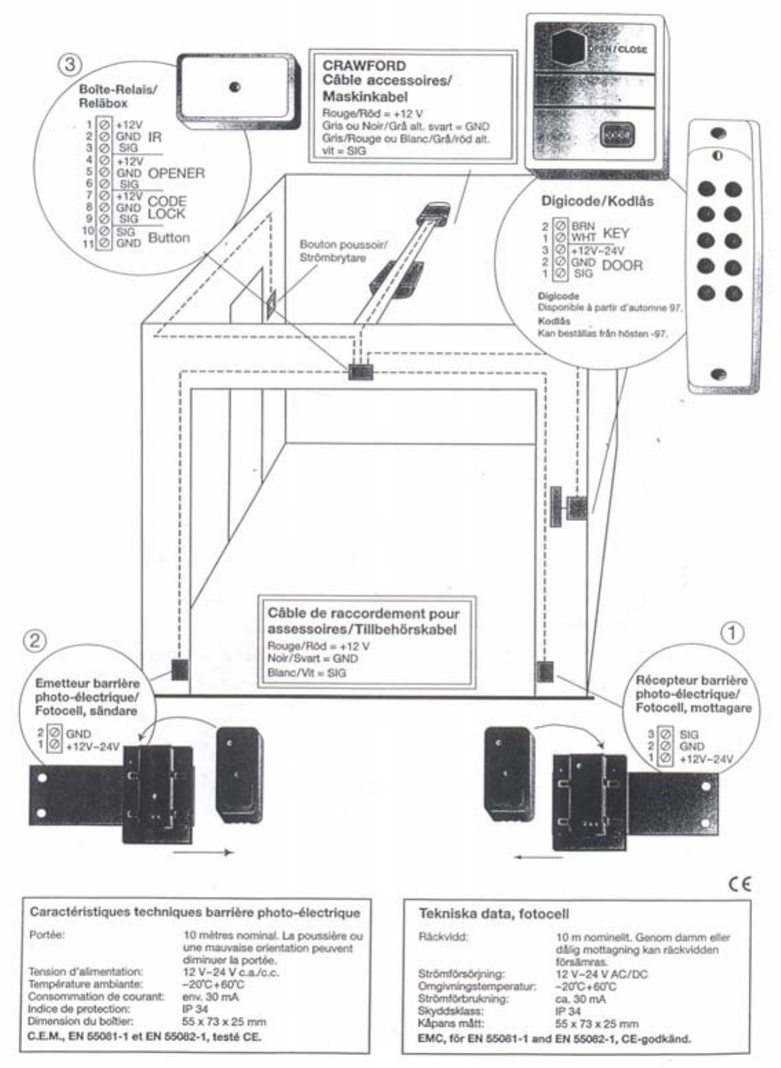
Installation et connexions
.ATTENTION! Si I'ouvre-porte de garage a dejil ete utilise,
dåsenficher le connecteur du reseau.
.Poser le cåble relieau bouton-poussoir de I'ouvre-porte au-dessus
du rail vers I'avant en direction de la boTte å relais.
.Couper le cåble å la longueur appropriee, et le connecter aux bornes
(Aparto)conformement au schåma des connexions @.
.Poser le cåble å trois conducteurs (fournQde la boTte å relais vers
le råcepteur (receiver) et I'emetteur (transmitter) de la barriere
photoelectrique.
.Connecter les deux extremies de cåble de I'emetteur et du recepteur
aux bornes IRde la boTteå relais, comme indique sur le schema des
connexions@. Les bornes GND(terre)et 12 Vrecoivent chacune
deux conducteurs.
.Connecter le råcepteur comme indique sur le schåma des con-
nexions (D, et I'emetteur, n'utiliser que les couleurs de conducteur
rouge (12 V)et noire (GND (terre»),et isoler le conducteur blanc avec
du rubanIsolant. .
.Placer les parties inferieuresdes boitiersde I'emetteur et du
råcepteur de la barriere photoelectrique sur les plaques de fixation
ou, en cas de montage mural,les visser dans les trous.
. Collerles etiqyettes de protection (fournies)sur chayun des marqua-
ges de couvercle de boitier.
.Poser le couvercle de la barrierephotoelectrique en appuyant
fortement jusqu'å ce qu'iIs'encliquette de fayon audible.
Alignement et controle
.Enficherle cåble de raceordement de I'ouvre-porte de garage au
reseau.
.Si la diode electroluminescente rouge clignote å I'enfichage, bien
que le faisceau lumineuxne soit pas interrompu, aligner I'emetteur et
le råcepteur jusqu'å ce que la diode electroluminescente s'eteigne.
.Contraler le bon fonctionnement de J'installation en interropmpant å
plusieurs reprises le faisceau lumineuxinfrarouge. Cela peut se faire
en passant la mainjuste devant I'undes deux dispositifs
photoelectriques. Si I'installationfonctionne correctement, on peryoit
une legere emission sonore et fa diode electroluminescente rouge de
I'emetteur s'allume.
.Activer "ouvre-porte de garage au moyen de I'emetteur portatif our
du bouton-poussoir interieur.
.Lars de la course d'ouverture de la porte, la barriere photoelectrique
est inactive. Par contre, lorsde la course de fermeture, I'ouvre-porte
s'arrete instantanement et revienten arrieresur environ 10 cm en
cas d'interruption du faisceau lumineux.Si le faisceau lumineux est
interrompu, "ouvre-porte ne demarre pas, niavec le bouton-
poussoir, niavec I'emetteur portatif.
[s)
Sakerhetspaket, 5506 C
Forpackningen innehåller:
. Relabox
. FotocelJ
.Kabel
. Fastplatta
. Montage-set
Mottagare och Sandare
3 x 0,25 mm2, langd 8 m
for montage på portskenor, speciell for Crawford
garageportar
Fastskruvar, muttrar och under1aggsbrickor
for fastplatta, skruvar och plugg for Relabox
Kopplings- och placeringsschema
.Montageanvisning
.Skyddsetiketter
Montage
Relabox:
.Placera och fast relaboxen på vaggen ovanfor elJervidsidan av
lopskenan, se placeringsschema.
Fastplattor:
.Borra2 st 6,5 mm hål ivarderavaggskena enligt fastplattornas
hålbild.
.OBS!Placera fastplattorna med ovankant max 150 mm från
golvet. Vidmontage av fotocellernapå vagg anvandes de tyra
skruvhålen i plastboxens underdel.
.Montera fastplattorna i vaggskenorna med skruvhuvudet från insid an
av skenan.
.For Crawford Privat monteras fastplattorna utanpå klammskydden.
Placera 2 st under1aggsskivor per skruv mellan klammskydd och
fastplatta. .
Installation/Kabeldragning
OBS!Dragurnatkontaktentil!dingarageportsoppnare.
.Fast maskinens treledande strombrytarekabel ovanpå lopskenan
fram til!relaboxen.
.Anpassa kabellangden och anslut till relaboxens kopplingsplint
enligt placeringsschema @.
.For1agg den medlevererade 3-led. kabel n från relaboxen till
mottagare och såndare.
.Anslutde båda kabelandarna frånmottagare och sandare enligt
placeringsschema @ i relaboxens kopplingsplint IR. Anslut både
såndare och mottagarens kabelandar til!GND och +12 V.
OBS! Isåndaren anvandes endast rott +12 Voch svart GND.
Den friavita kabeln skall isoleras med isoleringstape.
.Anslut mottagare eD och sandarE~ @.
OBS! Isåndaren anvandes endast rott +12 Voch svart GND.
Den fria vita kabeln skall isoleras med isoleringstape.
.Skjut på mottagare och såndare på fastplattorna så långt att den
linjerariytterkant av fastplattorna alt. vaggmontera enheterna med
skruvfastsåttning.
.De båda medlevererade skyddsetiketterna appliceras vid markering
på lockens framsidor.
.Tryckfast locken på plats.
Centrering och provning
.Anslut nåtkontakten til!din garageportsoppnare.
.Skullevidnatanslutningdenrodalysdiodenpå mottagarenIysa
fastanIjusstråleinteårbrutenmåstesandareoch mottagarejusteras
for korrekt centrering så att lampan slocknar.
.Kontrollerainstallationengenom att med t.ex. handen fleragånger
bryta Ijusstrålen. Ett klickande Ijud hOrs från relåboxen nar relaet
aktiveras, och den rOda ledlampan i mottagaren lyser.
.Aktivera garageportoppnaren via handsandare eller vaggstrom-
brytare.
.I uppåtgående rorelse har fotocellen ej någon funktion. I nedåtgå-
ende rorelse stoppar maskinen direktoch går c:a 10 cm tillbakaså
lange Ijusstrålenar bruten. Meden bruten Ijusstråle kan maskineriet
med vaggstrombrytare eller handsåndare ej startas. '"
..
~
o
'"
ti
~
E
li
\2
tt
~.
<
~
J!
.
'"
2
!
!j