Creative Products LOUNGER M User manual
Gewenten 43a
4704 RE Roosendaal
The Netherlands
T +31 (0)165 51 07 77
info@creative-products.nl
www.creative-products.nl
Installation movie
Lounger M
http://bit.ly/installationLoungers
CSP009-01 BI LOM P EN 3.1
LOUNGER M
INSTALLATION
VERSION 3.1
EN | 2019 | LOUNGER M INSTALLATION | 5
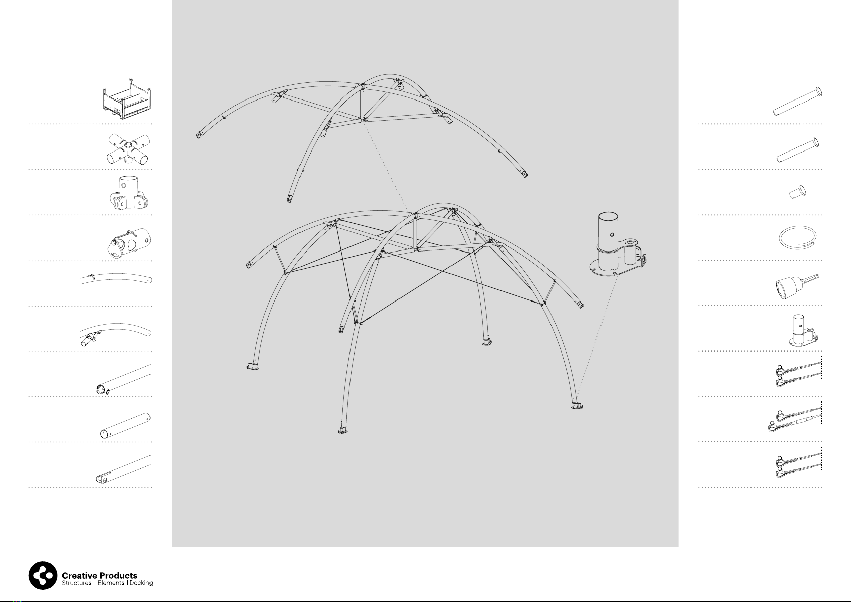
BOX CONTENTS
LOUNGER M
1x CS0628
X-connector
1x CS0629
Center sub
connector
4x CS0715
End connector
4x CS0287
Leg proile
ø90 mm - 308 cm
4x CS0716
Roof proile
ø90 mm
300 cm
4x CS0717
Sub proile
ø70 mm - 138 cm
1x CS0633
Center proile
ø70 mm - 62 cm
4x CS0719
Stabilization rod
ø20 mm - 47 cm
1x CS0733
Transportbox
8x CS0105
Locking pin (small)
ø70 mm proile
15x CS9064
Clevis pin 10x30
46x CS0248
Securing ring
1x CS0965
Adapter tool
4x CS0292
Foot
6x CS0298
Main cable
2x CS0718
Tensioning
cable
4x CS0688
Positioning
cable
20x CS0093
Locking pin (medium)
ø90 mm proile

!
EN | 2019 | LOUNGER M INSTALLATION | 76| LOUNGER M INSTALLATION | 2019 | EN
CS0715
End connector
CS0716
Roof proile
CS0093
Locking pin (medium)
ø90 mm proile
PLACE THE TENSION HOOK ON THE
CS0715 UP RIGHT IN THE ROOF PROFILE
STEP 1
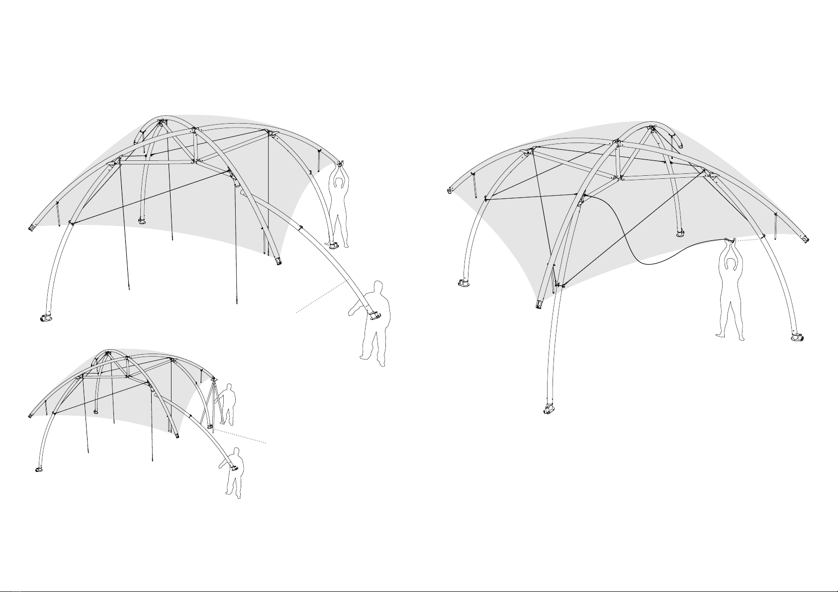
Connect CS0715 End connectors to the CS0716 Roof proiles
by using the CS0093 Locking pin medium and CS0248 Securing ring.
Connect it on the side where the rigging points for the cables are.
CS0248
Securing ring
Rigging point
Connect al 4 CS0716 Roof proiles on the CS0628 X-connector
using the CS0093 Locking pins medium and CS0248 Securing rings.
CS0628
X-connector
CS0716
Roof proile
STEP 2
CS0093
Locking pin (medium)
ø90 mm proile
CS0248
Securing ring

EN | 2019 | LOUNGER M INSTALLATION | 98| LOUNGER M INSTALLATION | 2019 | EN
Connect the CS0633 Center proile in the middle of the CS0628 X-connector.
Place the CS0629 Center sub connector on the other side of the CS0633 Center proile
using the CS0105 Locking pin small and CS0248 Securing ring.
STEP 3
CS0105
Locking pin (small)
ø70 mm proile
CS0248
Securing ring
CS0633
Center proile
CS0629
Center sub
connector
CS0628
X-connector
Connect all 4 CS0717 Sub proiles on the 4 CS0716 Roof proiles
using the CS0105 Locking pins small and CS0248 Securing rings.
Place the other end of CS0717 Sub proiles on the CS0629 Center sub connector
with the CS9064 Clevis pin 10x30 and CS0248 Securing ring.
If these parts are connected, you have inished the roof of the Lounger Large.
STEP 4
CS0716
Roof proile
CS0717
Sub proile
CS0105
Locking pin (small)
ø70 mm proile
CS0248
Securing ring
CS9064
Clevis pin
CS0629
Center sub
connector

EN | 2019 | LOUNGER M INSTALLATION | 1110 | LOUNGER M INSTALLATION | 2019 | EN
Connect the 4 CS0292 Feet to the 4 CS0287 Leg proiles
with the CS0093 Locking pins medium and CS0248 Securing rings.
Please note that the blind revit nut is on the top of the tube.
STEP 5
CS0093
Locking pin (medium)
ø90 mm proile
CS0248
Securing ring
CS0287
Leg proile
CS0292
Foot
Blind revit nut
Lift one side of the roof structure
(if you ordered a Tripod; place the Tripod in the corner under the roof structure)
and place 2tubes CS0287 Leg proiles on the roof structure
using the CS0093 Locking pins medium and CS0248 Securing rings.
STEP 6
CS0093
Locking pin (medium)
ø90 mm proile
CS0248
Securing ring
Tripod
CS0287
Leg proile

2
1
2
1
3
4
5
6
EN | 2019 | LOUNGER M INSTALLATION | 1312 | LOUNGER M INSTALLATION | 2019 | EN
Place the 2CS0718 Tensioning cables parallel on the roof structure and
the 2 CS0287 Leg proiles, with the tensioner at the leg.
These cables will put tension on the structure later In the build.
STEP 8
CS0718
Tensioning cable
Place 2CS0298 Main cables on one side of the structure
and connect them as a cross to the CS0287 Leg proiles.
STEP 7
CS0287
Leg proile
CS0287
Leg proile
CS0298
Main cable
CS0287
Leg proile
CS0287
Leg proile
STEP 9
Connect the other 4 CS0298 Main cables to the CS0716 Roof proiles.
CS0298
Main cable

2
1
4
3
EN | 2019 | LOUNGER M INSTALLATION | 1514 | LOUNGER M INSTALLATION | 2019 | EN
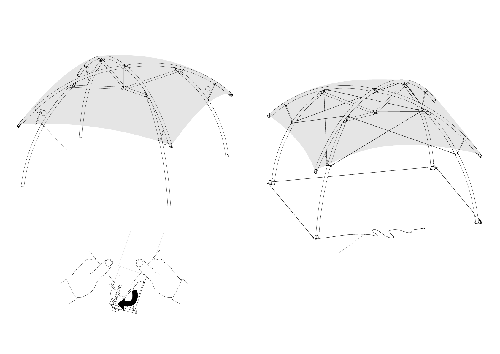
Place the 4CS0719 Stabilization rods on the CS0716 Roof proile with the
CS9064 Clevis pins and CS0248 Securing rings.
Do not connect to the CS0287 Leg proiles yet.
STEP 10
CS0719
Stabilization rod
Place the roof cover over the structure.
On the side where the Leg proiles have been mounted
you attach the metal hooks on the CS0715 End connector.
STEP 11
CS0715
End connector
EN | 2019 | LOUNGER M INSTALLATION | 1716 | LOUNGER M INSTALLATION | 2019 | EN
Now lift the other side of the structure
(if you ordered a Tripod place the Tripod in the corner under the roof structure)
and place the last 2 CS0287 Leg proiles on the roof structure
with the CS0093 Locking pins medium and CS0248 Securing rings.
STEP 12
CS0287
Leg proile
Tripod
Connect the last 4 CS0298 Main cables to the CS0287 Leg proiles (as in step 8).
Every opening between the legs shows crossed cables.
STEP 13
1
EN | 2019 | LOUNGER M INSTALLATION | 1918 | LOUNGER M INSTALLATION | 2019 | EN
Connect the 4CS0719 Stabilization rods which were already attached to the roof
to the CS0287 Leg proiles using CS9064 Clevis pins and CS0248 Securing rings.
STEP 14
Place the cover over the 2 remaining CS0715 End connectors.
STEP 15
CS0719
Stabilization rod
4
3
2
CS0688
Positioning cable
Connect the 4 CS0688 Positioning cables on the feet.
Place the feet in the right position and anchor the structure to the ground.
STEP 16

EN | 2019 | LOUNGER M INSTALLATION | 2120 | LOUNGER M INSTALLATION | 2019 | EN
ANCHORING & BALLAST
There are three options for anchoring & ballast: 1 Ground pins, 2 Concrete screws, 3 Ballast plates.
After the structure has been anchored remove the CS0688 Positioning cables.
STEP 17
BALLAST PLATE OUTSIDE
The ballast plates can be used when drilling
or the use of groundpins is not allowed.
BALLAST PLATE INSIDE
The ballast plates can be used when drilling
or the use of groundpins is not allowed.
CS0384
Ballast plate
CS0384
Ballast plate
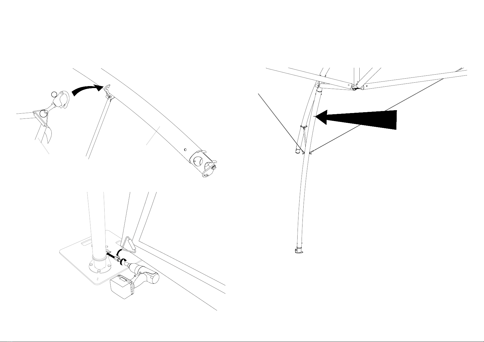
Put tension on the CS0718 Tensioning cables.
STEP 18
CS0715
End proile
CS0965
Adapter tool
At last put the cover on full tension at the CS0715 End proiles
by using the CS0965 Adapter tool on the drill.
STEP 19
CONCRETE SCREWS
Anchoring for permanent ixation on
a hard surface (when drilling is allowed).
GROUND PINS
Anchoring for permanent ixation
on soft ground (gras / sand / gravell).
CS9003
Concrete screws
CS9001
Groundpin S
EN | 2019 | LOUNGER M INSTALLATION | 2322 | LOUNGER M INSTALLATION | 2019 | EN
SIDEWALLS
First tension the roof. After that you can install the sidewalls.
Connect the top-left and top-right corner of the sidewall with
the pelicanhook in the corner of the CS0716 Roof proile.
Then connect bottom-left and right corner with CS0634 connector.
Put tension on the sidewall by using the drill.
STEP 20
CS0689
Lounger M sidewall
CS0716
Roof proile
For mounting (by example lights or television) use the blind revit nut, on the inside of the structure.
It is possible to mount up to 25 kg per leg.
STEP 21

A
B
A
B
B
A
A
B
EN | 2019 | LOUNGER M INSTALLATION | 2524 | LOUNGER M INSTALLATION | 2019 | EN
When you take down the structure irst take o the tension of the cover.
Then take the tension o the cables and release the stabilization rod.
Then it's a reverse build from step 14 till step 1.
STEP 22
STEP 23.1
1x CS0733 Transport box
Please make sure that CS0715 has been taken out of
the tube CS0716 to prevent transport damage.
Put the 4 CS0292, 4 CS0715 and 1 CS0628
in the transport box compartment A.
Place all 4 CS0287 Leg proiles on top of
the transport box take compartment A.
STEP 23.2
Place the CS0717 sub proile in compartment B
between the 4 holes on the sides of the transportbox.
Leave the small connectors in the proile.
Put the CS0633 next to the CS0717 sub proile.
If all the proiles are in place strap it with the supplied
strap on the transportbox.
Packing manual for the Lounger M Transport box.
STEP 23
STEP 23.3
Place the 4 CS0716 Roof proile above
compartment B.
STEP 23.4
In the included Toolbox you need to put the next parts:
4x CS0719 Stabilization rod ø20 mm - 51 cm
20x CS0093 Locking pin (medium)
8x CS0105 Locking pin (small)
15x CS9064 Clevis pin 10x30
46x CS0248 Securing ring
1x CS0965 Adapter tool
6x CS0298 Main cable
2x CS0718 Tensioning cable
4x CS0688 Positioning cable
1x CS0629 Center sub connector.
STEP 23.5
Place the toolbox in compartiment A
next to the connectors..
STEP 23.6
Connected the straps on each side of the
transportbox over the metal bars and secure
the proiles.
Now you are ready for transportation.
Table of contents
Popular Tent manuals by other brands


AC Infinity
AC Infinity CLOUDLAB Series user manual

Ozark Trail
Ozark Trail WMT14168.1D Assembly instructions

ARB Touring
ARB Touring ESPERANCE ANNEXE 804200 FITTING INSTRUCTION

Coleman
Coleman Air Awning Instructions for use

Kayoba
Kayoba 010571 operating instructions

Shire
Shire Forget - Me - Not Arbour Assembly