manuals.online logo
Brands
  1. Home
  2. •
  3. Brands
  4. •
  5. Creek Audio
  6. •
  7. Amplifier
  8. •
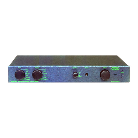
  9. Creek Audio A50i User manual

Creek Audio A50i User manual

CREEK A50i and A50i R SPECIFICATION
POWER OUTPUT (both channels) 50 W into 8
ΩΩ
POWER OUTPUT (one channel) 60 W into 8
ΩΩ
POWER OUTPUT (one channel) 80 W into 4
ΩΩ
Not recommended for use into more than one pair of 4
Ω
loudspeakers.
TOTAL HARMONIC DISTORTION < 0·05% 20 Hz to 20 kHz
FREQUENCY RESPONSE 3 Hz to 25 kHz - 1 dB
SLEW RATE > 40 V per
µµ
S
INPUT SENSITIVITY (passive) 450 mV
SIGNAL TO NOISE RATIO (‘A’ weighted) > 100 dB
SEPARATION (line input) > 60 dB at 1 kHz
MM SENSITIVITY AND IMPEDANCE (when fitted) 3.5 mV 47k
ΩΩ
MC SENSITIVITY AND IMPEDANCE (when fitted) 0.75 mV 1k
ΩΩ
POWER CONSUMPTION (at idle) < 45 W
POWER CONSUMPTION (full power 10% THD) 260 W
WEIGHT 6 kg, 13.2 lbs
SIZE 430 x 65 x 250 mm
17” x 2·75” x 10''
MAINS VOLTAGE @ 60Hz 100V Japan, 115V North America
@ 50Hz 230/240V Europe, Asia and UK
MAINS VOLTAGE AND FREQUENCY IS INTERNALLY SET FOR THE COUNTRY OF USE
Creek Audio Ltd reserves the right to change or modify the specification of its products without prior warning.
Creek Audio Ltd
12 Avebury Court, Mark Road, Hemel Hempstead, HP2 7TA England
Tel: +44 (0)1442 260146 Fax: +44 (0)1442 243766
E-mail: [email protected] Internet: www.creekaudio.com
Designed and made in the UK.
Creek A50i
& A50i R
Operating
Instructions
Thank you for purchasing the A50i amplifier.
You are now in possession of a State of the Art Integrated Amplifier. The functions and
operation of the A50i are extremely simple. However, the following notes are provided
to explain all aspects of its design and use. These instructions apply to both the
standard and remote versions of the A50i.
MAINS CONNECTION
When unpacking the amplifier please keep the packing material in a safe place for
possible future use. In the pack there is a separate mains cable with a moulded plug
suitable for connecting to the mains supply in the country of use. The IEC socket end
of the cable should be firmly inserted into the connector on the rear panel marked
"Mains Input".
The high quality performance of the amplifier will be impaired if the electrical supply to
it is in poor condition. If in doubt, consult a qualified electrician or your supplying
dealer. The "Mains Input" connection is also fitted with a fuse, specifically suited to the
supply voltage of the country of use. The correct value is clearly marked on the rear
panel next to the Mains Input.
Should it be necessary to replace the fuse, ensure that you use the same type as
specified on the rear panel:
i.e: 5 x 20mm cartridge type T 2A surge resisting for 220-240V 50Hz AC, T 4A
surge resisting for 110-120V 60Hz AC.
LOUDSPEAKER CONNECTIONS
The loudspeakers should be connected using a suitable pair of cables designed
specifically for audio use. The screw terminals allow for either bare wire or spade con-
nectors to be passed through the hole or around the bush. Tighten the terminal fully after
fitting the speaker wire. Please consult your dealer for advice if you are unsure.
It is very important to connect the loudspeakers to the loudspeaker terminals in the
correct phase. Positive and negative sides of the cable are normally polarised with a line
or a raised bump on the positive side. If one channel is not connected in the same way
as the other, a severe loss of bass performance and an incorrect stereo image will result.
It is not recommended to use loudspeakers of less than 4W resistance or more than two
pairs of 8W speakers running from the amplifier at one time. However, bi-wiring of one
pair of speakers, using the four terminal posts, can improve the sound of your system
without changing the load resistance (consult your dealer for more details).
N.B. It is VERY IMPORTANT not to short the loudspeaker cables together when the
other ends are still connected to the working amplifier, otherwise permanent
damage can result. If it is necessary to move or change the location of your
loudspeakers, make sure that you switch off the amplifier from the mains first.
INPUT CONNECTION
All the line inputs on the amplifier are passive as standard and have a sensitivity in the
region of 450mV's for maximum power output. The tape input is in a loop with the tape
output, enabling you to record anything you can hear, or in other words, Monitor
recordings without interrupting the signal. A button on the front panel, marked Tape
Monitor, should be in the out position for normal use and pressed in for monitoring from
tape. The rotary selector switch on the left-hand side of the amplifier is used to select
any of the desired inputs. As all the line input levels are the same, it is not necessary to
use the precise inputs as designated. You may, for example, plug a CD player into the
Tuner input and obtain exactly the same result or performance as the dedicated CD
input. However, for added flexibility, the first input on the A50i is for use as vinyl Disc or
Auxiliary Line, and an optional low noise MM or MC phono amplifier module is
available, which replaces the standard passive Link PCB, internally.
VOLUME LEVEL
The volume control, situated on the right hand side of the front panel, should be used to
alter the relative level of the sound output from the amplifier. It is important to realise
that the volume control only acts to reduce, or attenuate, the incoming signal to the
power amplifier stage. The maximum power of the amplifier is available only (when the
volume control is fully clockwise) if the level of signal available from the line level
equipment is sufficient to drive it to clipping; this will be in the region of 450mV's.
The volume control is necessary to balance the level from one piece of equipment to
another. It does not increase the power of the amplifier and, if it is found necessary to
have the volume control set to a position which is considered to be high, before the
desired level of volume is obtained, it does not necessarily mean that the amplifier is
having to work "flat-out". Consult your dealer if you feel you need more advice.
OPERATING THE A50i
Make sure that the unit is on a suitable table or Hi-Fi equipment cabinet. It is important
to allow adequate ventilation to the heatsink in the centre of the unit. Avoid obstruction
of the ventilation slots on the top cover. It may be necessary to place the amplifier on
the top of other equipment to allow for this.
Always have the volume control set at minimum ( counter-clockwise ) when switching on
and off, to avoid sudden loud noises when the muting relay switches off. Select the
desired input on the rotary selector and switch the amplifier on with the push button
marked Power on the right hand side of the front panel. Adjust the volume gently and
settle down to listen. It should be noted that the rotary input selector has 5 positions, not
four. The first position at the top is Park, or Mute, in which no signal can pass. The
remaining positions are identical to the input markings on the front panel.
Your A50i amplifier is designed to give you years of reliable use. However, it is
necessary to take care of your possession, so never overheat it or short-out the
speaker connections. If an adjustment is needed to the plug-in Phono circuitry, it is
always advisable to return it to the supplying dealer for his expert help. If you are
unfortunate enough to need service work to be carried out on your amplifier, it should be
returned to your dealer in the original packing material, if possible.
REMOTE CONTROL VERSION A50iR
N.B.The A50i is designed to work properly in normal domestic operating conditions.
However, the amplifier’s performance may be seriously affected if sited near to, or
in the room with, a radio transmitter such as a mobile phone or CB radio rig, etc.
Re-siting the A50i, or the radio, will normalise the situation.
The A50i R remote version works in exactly the same way as the standard
but has the capability of remote operation of the volume control and mute.
The Creek ARC 53 remote handset is supplied. Volume up and down and
mute buttons can be used with the A50iR, the remaining buttons are for use
on other Creek products and do not control anything on the A50iR.
The power LED will change colour from green to red when muted. Volume
changes will cause the LED to flash yellow. Muting will be cleared if the volume is
moved up but not down. Only the remote handset can clear the mute, or switching the
power off for 10 secs and then on again. The A50i remote circuit is designed to go into
sleep mode when not in use, to avoid interfering with the amplifier and the power LED
will stay green for normal operation.
This manual suits for next models

1

Other Creek Audio Amplifier manuals

Creek Audio A42 User manual

Creek Audio

Creek Audio A42 User manual

Creek Audio EVO User manual

Creek Audio

Creek Audio EVO User manual

Creek Audio Evolution 2 User manual

Creek Audio

Creek Audio Evolution 2 User manual

Creek Audio EVOLUTION 50A User manual

Creek Audio

Creek Audio EVOLUTION 50A User manual

Creek Audio OBH-21mk2 User manual

Creek Audio

Creek Audio OBH-21mk2 User manual

Creek Audio VOYAGE i20 User manual

Creek Audio

Creek Audio VOYAGE i20 User manual

Creek Audio OBH 21 User manual

Creek Audio

Creek Audio OBH 21 User manual

Creek Audio Destiny User manual

Creek Audio

Creek Audio Destiny User manual

Creek Audio Stereo Power Amplifier User manual

Creek Audio

Creek Audio Stereo Power Amplifier User manual

Creek Audio a52 User manual

Creek Audio

Creek Audio a52 User manual

Creek Audio Wyndsor User manual

Creek Audio

Creek Audio Wyndsor User manual

Creek Audio OBH-15 Mk2 User manual

Creek Audio

Creek Audio OBH-15 Mk2 User manual

Creek Audio EVOLUTION 100A User manual

Creek Audio

Creek Audio EVOLUTION 100A User manual

Creek Audio OBH-8 User manual

Creek Audio

Creek Audio OBH-8 User manual

Creek Audio OBH22 User manual

Creek Audio

Creek Audio OBH22 User manual

Creek Audio EVOLUTION 50A User manual

Creek Audio

Creek Audio EVOLUTION 50A User manual

Creek Audio 5250 User manual

Creek Audio

Creek Audio 5250 User manual

Creek Audio OBH 15 User manual

Creek Audio

Creek Audio OBH 15 User manual

Creek Audio 4040 A User manual

Creek Audio

Creek Audio 4040 A User manual

Creek Audio OBH-12 User manual

Creek Audio

Creek Audio OBH-12 User manual

Creek Audio OBH-22 User manual

Creek Audio

Creek Audio OBH-22 User manual

Creek Audio Destiny 2 User manual

Creek Audio

Creek Audio Destiny 2 User manual

Creek Audio EVOLUTION 50A User manual

Creek Audio

Creek Audio EVOLUTION 50A User manual

Creek Audio OBH-11 User manual

Creek Audio

Creek Audio OBH-11 User manual

Popular Amplifier manuals by other brands

Plinius SA-103 instruction manual

Plinius

Plinius SA-103 instruction manual

Sutherland Ph.D. owner's manual
Sutherland

Sutherland Ph.D. owner's manual

Fredenstein HD Reference operating manual

Fredenstein

Fredenstein HD Reference operating manual

Audio Authority 985DTV How to use

Audio Authority

Audio Authority 985DTV How to use

Monacor PA-4240 instruction manual

Monacor

Monacor PA-4240 instruction manual

McIntosh MC 22O5 Service information

McIntosh

McIntosh MC 22O5 Service information

Velodyne Subcontractor SC-602 Specifications

Velodyne

Velodyne Subcontractor SC-602 Specifications

Knox Video t-CAT Operation manual

Knox Video

Knox Video t-CAT Operation manual

Crate VC-50H owner's manual

Crate

Crate VC-50H owner's manual

Pace PX 200BL Manual for installation

Pace

Pace PX 200BL Manual for installation

JBL 6230 user manual

JBL

JBL 6230 user manual

Carlsbro KICKSTART 25 user guide

Carlsbro

Carlsbro KICKSTART 25 user guide

Peavey CS 3000H user guide

Peavey

Peavey CS 3000H user guide

Yamaha WXA-50 Service manual

Yamaha

Yamaha WXA-50 Service manual

Monacor IMG STAGELINE MPR-1 manual

Monacor

Monacor IMG STAGELINE MPR-1 manual

Rotel RA-06 SE owner's manual

Rotel

Rotel RA-06 SE owner's manual

Crown Macro Reference supplementary guide

Crown

Crown Macro Reference supplementary guide

Gallien-Krueger 200MK Operation instructions

Gallien-Krueger

Gallien-Krueger 200MK Operation instructions

manuals.online logo
manuals.online logoBrands
  • About & Mission
  • Contact us
  • Privacy Policy
  • Terms and Conditions

Copyright 2025 Manuals.Online. All Rights Reserved.