Crenova 6016A User manual

Operating Manual of Crenova 6016A Clamp Digital Multimeter
I. Overview
Crenova 6016A is a battery-driven 3 1/2 digital clamp meter for automatic range conversion which is
characterized by stable performance and high reliability. This meter applies 16mm word height LCD with
distinct readings, and features maximum hold, data hold and automatic on-off function.
This clamp meter can be used for measuring parameters such as DC voltage, AC voltage, resistance,
diode and on-off test. The complete meter is cored by dual integral A/D conversion of large scale
integrated circuit and features automatic range conversion function. It is a high-performance meter well
received by lab, factory, radio amateur and family.
Warning: before using the clamp meter, please read through “Safety Precautions”.
We have already sent an online manual to you, please check your email.You can reply us in the email
about any question. Thank you.
II. Open-case inspection
Open the packing case and check if the following items are missing or damaged.
One 6016A+digital clamp meter
One leather box
One certificate of inspection
One copy of operating manual
One pair of test leads
Two 1.5V AAA batteries
III. Safety precautions
Please note “warning sign and warning words”. It means cases or behavior which may pose
danger to user or cause damage to the clamp meter or device under test.
This meter is strictly in line with GB4793 Safety Requirements on Electronic Measuring Instrument,
IEC61010 and IEC1010-2-032 safety standard. It complies with safety standard for double insulation,
over-voltage CAT III 300V and pollution class 2.
Before use, please read through the operating manual.
1.When voltage above 30V, AC power line with inductive load is measured. When AC power line during
electric fluctuation is measured, please be cautious of electric shock.
2.Before measuring, check if the measurement function switch is at correct position. Check test leads for
reliable contact, correct connection and good insulation to avoid electric shock.
3.Clamp meter only meets safety standard when used with its supporting test leads. When test lead line is
damaged, please replace with lead line of the same model or the same electric specification.
4.Do not replace the battery inside with other non-confirmed or non-recognized one. Use battery of the
same model or electric specification only. Before replacing, the test lead must be away from the
measurement point and make sure the input end has no signal.
5.When do electrical measurements, human body should have no direct contact with earth. Do not touch
any metal terminal, output terminal or lead clamp which have exposed ground potential.
6.Do not store or use it in high temperature, high humidity, inflammable, explosive environment or high
magnetic field.

7.Measure limit voltage which is beyond allowed range will cause damage to the clamp meter and injury
to operator. Allowable limit voltage is indicated on the surface of clamp meter. Do not measure input
signal which beyond this standard so as to prevent electric shock or damage to the clamp meter.
8.Do not apply 600V above voltage between clamp meter terminal and earth so as to prevent electric
shock or damage to the clamp meter.
9.Do not attempt to calibrate or repair the clamp meter. When necessary, it should be done by personnel
with specialized training or qualification.
10.When measuring, function/range selection switch must be at correct range gear. When shifting
function/range selection switch, please disconnect the line of test lead from the object under test, and
make sure the input end has no signal input. Do not shift function/range selection switch during
measurement.
11.When LCD shows “ ”, please replace battery in time to make sure measurement accuracy.
12.Do not change clamp meter circuit without permission, so as to prevent damage to clamp meter or
safety risk.
IV. Safety symbols
Warning
DC
High
voltage
AC
Earth
AC/DC
Double
insulation
European
Union directive
conformity
Battery
under-volta
ge
Fuse
V. Surface structure
1.Clamp sensor/Jaw;
2.Instrument meter;
3.Trigger;
4.Function/range switch; for
selecting measurement functions and ranges.
5.(SELECT) shift key of diode/buzzer;
6.(RANGE) shift key of auto/manual;
7.(HOLD) data hold key;
8.(MAX) maximum hold key;
9.LCD display screen;
10.COM input hole: negative input
end, insert black test lead in;
11.VΩ input hole: measure voltage,
resistance, diode and positive input
end of on-off test, insert red test lead in;

VI. Display symbols
1.Low battery indicator;
2.Negative polarity indicator;
3.AC signal measurement indicator;
4.DC signal measurement indicator;
5.Automatic range indicator;
6.Diode measurement indicator;
7.Continuous inspection indicator;
8.Maximum measurement indicator;
9.Data hold indicator ;
10.Relative value measurement indicator;
11.Triode measurement indicator;
12.Degree centigrade measurement indicator;
13.Fahrenheit measurement indicator;
14.Resistance measurement unit (Ω ohm, kΩ kiloohm, MΩ megohm);
15.Current measurement unit (A ampere, mA milliampere, uA microampere);
16.Voltage measurement unit (V volt, mV millivolt, uV microvolt).
Note: item 10, 11, 12 and 13 are not available for 6016A+.
VII. Key functions and auto power-off
⑴SELECT:Press the button to select indicated measurement function when there are two or more
measurement functions on the same gear. It shifts between diode and buzzer measurements.
⑵RANGE: The meter is in automatic range when starts up, press the “RANGE” button to activate
manual range mode. In the mode of manual range, each press lets the meter skip to the previous shift.
When it goes to the highest shift, it goes back to the lowest shift automatically. The procedure
repeats again in the same order. Press the “RANGE” button over 2 seconds, it will exit from manual
range measurement mode and shift to automatic range measurement mode.
⑶HOLD:Press the “HOLD” button, the measurement value showed on the screen will be locked.
Press this button again, it will unlock and enter the state of regular measurement.
⑷MAX :Press the “MAX” button, the display screen will show maximum value of the whole
measurement process automatically. Press this button again, it will cancel maximum reading hold
status and enter the state of regular measurement.
⑸Auto power-off function: In measurement process, if function button or function/range selection
switch has no operation within 15 minutes, the meter will “power-off automatically”. In the mode
of auto power-off, press function button (valid operation) or rotate function/range selection switch,
the meter will “power on automatically”and enter the measurement mode. Press and hold
“HOLD”button when start up, the auto power-off function will be canceled.
Note: “Auto power off”refers to a dormant state. In dormant mode, small current (about 5μA)
will be consumed. If it will not be used for a long time, please cut off power and take the battery out.
⑹Buzzer: Press any one of functional buttons at any gear, if the button is effective, the buzzer will
beep. (2/20A buzzer will make no sound , and keep silence if the operation is invalid.) About 1
1
2
3
4
5678910
11
12
13
14
15
16

minute before automatic power off, the buzzer will send 5 beeps continuously for warning; before
power off, the buzzer will send a long beep for warning. When resistance of on-off measurement is
lower than 70Ω, buzzer beeps.
⑺Valid Operation: Not all buttons worked at any gear. The clamp meter only worked when the operation
is valid. You may select the relative operation or wake up clamp meter in dormant mode under the valid
operation, as shown in table below ( means valid):
VIII. Features
1.General features
1-1. Display mode: LCD
1-2. Maximum display: 1999(3 1/2)digit automatic polarity display and unit display;
1-3.Measurement mode: dual integral A/D conversion;
1-4. Conversion rate: 3 times/second;
1-5. Over range display: “OL”is shown at the top of the display;
1-6. Low voltage display: “ ” appears (about 2.4V);
1-7.Auto power off function;
1-8.Maximum opening jaw size: 32mm diameter;
1-9.Estimated maximum size of electric current wire: 30mm diameter;
1-10.Effects of magnetic fields: the meter can be affected by magnetic fields nearby. The display may be
unstable or indicate incorrect measurement values;
1-11.Test position error: when measuring current, place measurement object in the center of clamp jaw,
otherwise it may generate certain additional error;
1-12. Working environment: 0~40℃, relative humidity <80%;
1-13.Storage environment: -10~50℃, relative humidity <80%;
1-14. Power source: two 1.5V batteries (“AAA”7#);
1-15. Dimension (size): 210mm×76mm×37mm (L×W×H)
1-16. Weight: about 180g (batteries included).
2.Technical features
Accuracy is ± (% reading + number of digits)
for ensuring accuracy.
Ambient temperature: (23±5)℃, relative
humidity <75%.
Warranty is one year, starting on shipping date.
2-1.DC voltage measurement (see Figure 1)
Key
SELEC
T
RANGE
HOLD
MAX
Invalid
Invalid
Ω
Invalid
Invali
d
Invalid
Invali
d
2/20A
Invalid
200/60
0A
Invalid

A)Rotate function/range selection switch to .
B)Insert red test lead and black test lead to VΩ and COM input
jacks respectively.
C) Connect test end of the test lead with circuit under test
or power supply in parallel. Polarity of red test lead and
voltage value under test will be indicated on the display
screen at the same time.
D)Read the measured value from the display screen.
DC Voltage (DCV) technical indicator:
Range
Accuracy
Resoluti
on
200mV
±(0.5%+4d
)
0.1mV
2V
1mV
20V
10mV
200V
100mV
600V
±(1.0%+6d
)
1V
Input impedance: 10MΩ
Overload protection: 600V DC or AC peak;
Figure 1
2-2.AC voltage measurement (see Figure 2)
A)Rotate function/range selection switch to .
B)Insert red test lead and black test lead into VΩ and COM
input jacks.
C)Connect test end of the test lead with circuit under test or
power supply in parallel.
D)Read the measured value from the display screen.
Technical index of AC Voltage (ACV):
Range
Accuracy
Resoluti
on
200mV
±(1.5%+20d)
0.1mV
2V
±(0.8%+10d)
1mV
20V
10mV
200V
100mV
600V
±(1.0%+10d)
1V
Input impedance: 10MΩ.
Frequency response: 40~200Hz.
Display: average value response (calibrate by effective value of
sine wave).
Overload protection: 600V DC or AC peak;
Figure 2

Note:
·Do not measure DC voltage or AC peak voltage higher than 600V.
·When measuring high voltage, please pay more attention to prevent electric shock.
After measuring, disconnect test lead from circuit under test immediately.
2-3.Resistance measurement (see Figure 3)
A)Rotate function/range selection switch to Ω gear.
B)Insert red test lead and black test lead to VΩ and COM input jacks respectively.
C)Connect test end of test leads with resistance under test. The resistance value will be indicated on the
display screen.
D)Read the measured value from the display screen.
Note: when testing resistance, turn off power supply of the circuit, and fully discharge capacitance.
Figure 3
If resistance is under an open-circuit or resistance exceeds maximum range of the clamp meter, the
instrument will indicate “OL”.
When resistance above 1MΩ, it will take the meter several seconds to make readings stable. It is normal
for high resistance measurement.
When measuring resistance, do not input voltage value. Do not attempt to take any measurement that
exceeds the limits. Exceeding the limits could cause electrical shock and damage to the clamp meter.
·After measuring, disconnect test lead from circuit under test immediately.
Technical index of resistance (Ω)
Range
Accuracy
Resoluti
on
200Ω
±(0.8%+5d)
0.1Ω
2kΩ
±(0.8%+4d)
1Ω
20kΩ
10Ω
200kΩ
100Ω
2MΩ
1KΩ
20MΩ
±(1.2%+10d)
10KΩ
Open-circuit voltage: 200mV Overload protection: 250V DC or AC peak.
Note: When using 200Ω range, you may short-circuit test lead

first. When measuring the resistance of the lead, please deduct it from actual measurement.
2-4.Diode measurement and on-off test
2-4-1.Diode measurement (see Figure 4)
Figure 4
A)Rotate function/range selection switch to .
B)Insert red and black test leads to VΩ and COM input jacks respectively.
C)Connect red test lead with positive pole of diode and black test lead with negative pole of diode.
D)Read the measured value from the display screen.
Note: if diode is under an open-circuit or polarity connection is wrong, the display screen will show
“OL”. When measuring diode under the circuit, turn off power supply of the circuit and fully discharge
capacitance. After measuring, disconnect test lead from circuit under test immediately.
2-4-2.On-off test (see Figure 5)
A)Rotate function/range selection switch to .
B)Press SELECT button to select on-off measurement function.
C)Insert red and black test leads to VΩ and COM input jacks respectively.
D)Connect test lead with both ends of circuit under measurement in parallel.
E)If resistance between both ends of circuit is lower than 60Ω, built-in buzzer beeps.
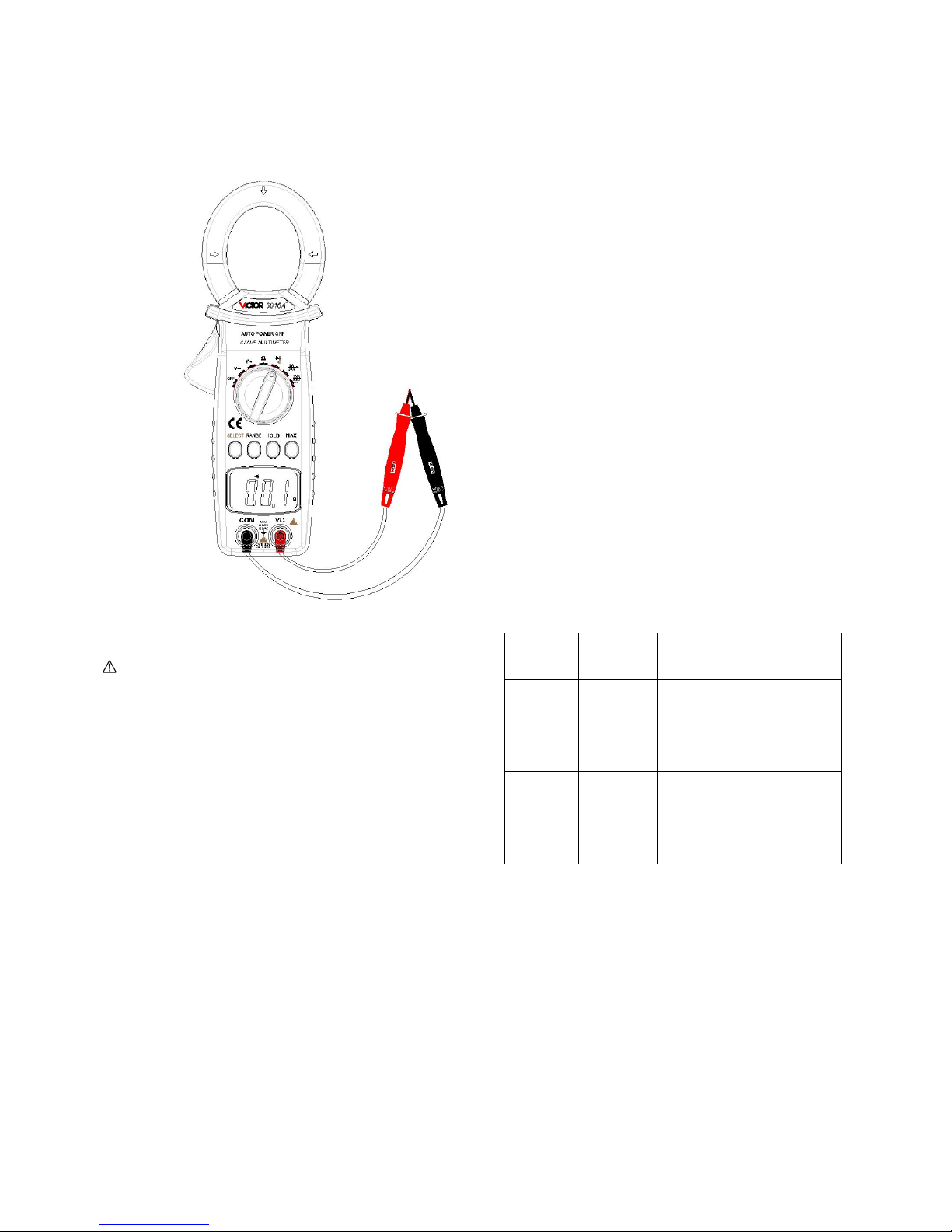
Figure 5
Technical index of diode and on-off test
Overload protection: 250V DC or AC peak.
Note:
·If circuit under measurement is in open-circuit mode,
the display screen will show “OL”.
When testing circuit on-off, cut off its power and fully
discharge capacitance.
·After measuring, disconnect test lead
from circuit under measurement immediately.
2-5.AC measurement (see Figure 6)
A)Rotate function/range selection switch to “2/20A” or
“200/600A”.
B)Press and hold clamp jaw trigger to open clamp jaw. Pick up conductor under measurement by clamp
jaw, then release trigger slowly until clamp jaw is fully closed. Please make sure the conductor is in the
center of clamp jaw, otherwise it will cause additional error. The clamp meter can only measure one
current conductor at one time. If measuring two or more conductors at the same time, the readings will be
incorrect.
Range
Resoluti
on
Description
Diode
1 mV
Open-circuit voltage is
about 1.4V, forward
voltage drop is about
0.5~0.8V.
On-off
test
0.1Ω
Open-circuit voltage is
about 0.45V, when it is
lower than 70Ω, the
buzzer beeps.

Technical index of ACA:
Range
Accuracy
Resoluti
on
2A
±(3.5%+15d
)
0.001A
20A
±(3%+10d)
0.01A
200A
±(3%+10d)
0.1A
600A
±(3.5%+15d
)
1A
Note: frequency response: 50Hz;
Maximum input 600A, input time should not exceed 1 minute.
At AC gear, if clamp meter is near to a strong magnetic field,
it will indicate unstable or incorrect induction reading,
but it will not affect measurement result.
Figure 6
IX. Service and maintenance
Warning:
Before open the bottom cover, please remove test rod first to avoid electric shock.
1.Ordinary servicing
1-1. This clamp meter is a high precision instrument. User is not allowed to modify circuit;
1-2.Please keep it from water and dust, do not bump or drop the meter;
1-3 .Do not store or use the clamp meter in high temperature, high humidity, inflammable, explosive
environment or strong magnetic field;
1-4.Please use wet cloth and gentle cleaning agent to clean surface of the clamp meter. Do not use strong
solvent such as abradant or ethyl alcohol;
1-5.If the meter will not be used for a long time, please take batteries out in case of leaking liquid of
batteries, which will corrode the clamp meter;
1-6. Do not let the peak value of DC or AC voltage input higher than 600V;
1-7.Do not measure voltage on current gear, resistance gear, diode gear and buzzer gear;
1-8.Do not use the clamp meter if the battery is not installed or
rear cover is not tightened.
2.Install or replace batteries
When the meter is in use, please be noted that the service condition of 1.5V batteries. If the screen shows
, please replace batteries according to Figure 7.
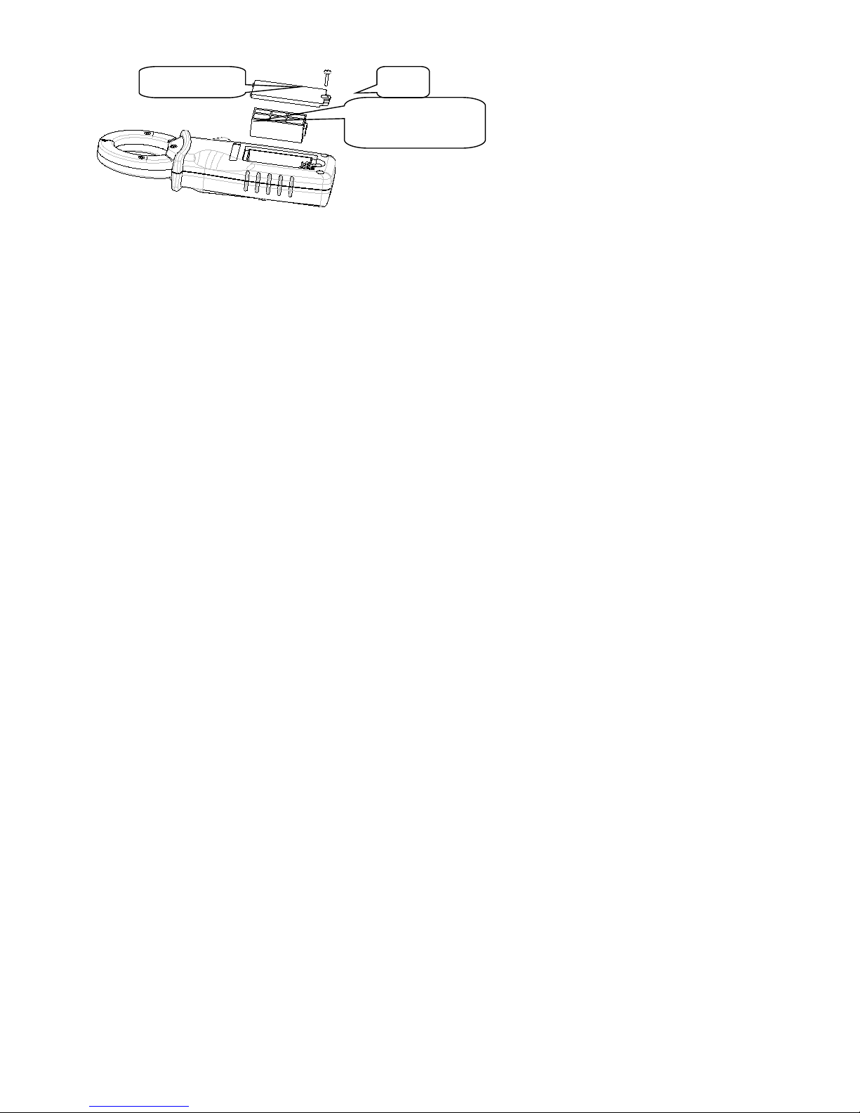
Figure 7
Please follow steps below:
2-1.Turn off the clamp meter, and remove test lead or the clamped current conductor at input end;
2-2.Make panel face down, and unscrew battery cover, remove the battery cover and take the battery box
out;
2-3.Remove old batteries from the battery box and install new batteries according to polarity indication;
2-4.Please use batteries with the same model. Do not insert improper batteries;
2-5.After installing new batteries, put battery box inside the device, close the battery cover and secure the
screw.
Content in this manual is considered correct. If users find any errors or omissions, please contact
the manufacturer;
Please read the Safety note and Warning carefully, the company shall not be held liable for any
accidents or damages caused by user’s wrong/improper operation.
Battery cover
Screw
Batteries in battery box
Table of contents
Other Crenova Multimeter manuals


