13
To select the next available (free) memory location, press the UP/DOWN buttons
(reference number between 0 and 9).
Make your next measurement and then repress the SET/R button. This memory
location is also now occupied. If you select a memory location already occupied
by a measurement value, the location is overwritten with the new value. Quit this
function by pressing only the “FUNC” button or the SET/R button.
Important!
Pressing the SET/R button once too often when saving a measu-
rement value quits the subfunction. However, the value you wis-
hed to save is not lost and can be called up via the following sub-
function.
f 7 RCL (= Recall)
To call up the reference values you have saved, use this function. This is what you
do:
Keep pressing the FUNC button until RCL flashes. Repress the SET/R button. RCL
stops flashing, replaced by the reference number. You can now recall the reference
number corresponding to the memory location where the desired measurement
value is stored by pressing the UP/DOWN keys. Then press the SET/R button to read
out the saved value. The value read out is shown on the upper subdisplay, and the
contents of the following memory locations in the subdisplays below (memory loca-
tions are not numbered). If you wish to quit this subfunction, press the SET/R or
FUNC buttons. You are then returned to default.
f 8 CMP (= Comparison)
This subfunction enables you to make a high/low comparison by comparing the hig-
hest and the lowest reference values saved against your current measurement value.
The middle subdisplay then shows “Lo” if the current measurement value is lower
than the lowest saved measurement value, and “Hi” if the current measurement
value is higher than the highest saved measurement value. If “Pass” is shown
(accompanied by a beep), the current measurement value is between the higher and
lower limit values set. The lower limit value is shown in the upper subdisplay (LOW),
and the upper limit value in the lower subdisplay (HIGH).
To activate this function, press the “FUNC” button until the code “CMP” is shown at
the top of the digital display. Repress the SET/R button. The code for polarity then
starts flashing next to the upper subdisplay.
Now set the minimum value (lower limit value) with polarity and weighting, by pressing
the “UP” and “DOWN” buttons. After each change, confirm you entry by pressing the
SET/R button once, which brings you to the position of the next digit. When the lower
limit value (LOW) has been set, the polarity code is displayed in the lower subdisplay.
12
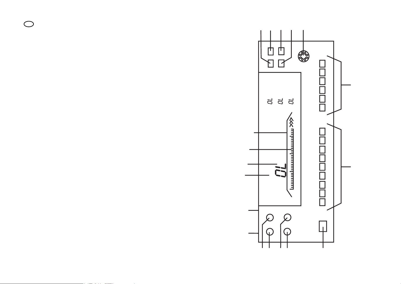
f 3 Data Hold D-H
With D-H, a measurement value is held in the middle subdisplay when the SET/R
button is pressed. If you wish to quit this subfunction, press the SET/R button a
second time (keeping it down a little longer), or the FUNC button. You then return to
default.
f 4 Auto Hold A-H
When set to this function, the measuring device saves the MIN and MAX measure-
ment values, which are automatically refreshed if there are changes to the measure-
ment values. You can see the MIN value in the left-hand subdisplay, the MAX value in
the right-hand display. The middle subdisplay shows the average value (AVG). This
value is also refreshed as applicable.
In this subfunction, keep pressing the FUNC button until the code “A-H” flashes.
Then press the SET/R button once. The code A-H stops flashing. The measurement
can start.
If you wish to quit this subfunction, press the SET/R button a second time, or the
FUNC button. You then return to default.
f 5 REL ( = Relative)
This setting allows you to compare a reference value with a subsequently measured
value. This is what you do:
Start by setting the FUNC button to REL and then press the SET/R button once.
Next, select polarity by pressing the UP and DOWN buttons. Then, press the SET/R
button.
To set the relative value from left to right, repress the UP and DOWN buttons. After
each digit setting, repress the SET/R button. This brings you to the next digit position.
When the relative value has been set, press the SET/R button again. The measuring
device now displays the difference between the value saved and the subsequent
measurement value in the subdisplay, while the current (true) measurement value is
displayed on the main display. The % difference is shown in the upper subdisplay.
The offset value is shown in the middle subdisplay. The reference value set is shown
in the lower subdisplay. If you wish to quit this subfunction, press the SET/R button a
second time, or the FUNC button.
f 6 MEM ( = Memory)
This function allows you to save up to 10 measurement values (reference number 0
to 9). This is what you do:
Keep pressing the FUNC button until you see MEM flashing in the display. Then,
press the SET/R button. MEM stops flashing, and the reference number flashes
instead. Make your measurement and press the SET/R button once if you wish to
save the measurement value to the first memory location = reference number 0.