Ovens FL-2340-D
Rev. 0 (5/13) Page 6 of 12
Call Toll-free: 877-CRES COR (273-7267) • Fax: 800-822-0393 • www.crescor.com
5925 Heisley Road • Mentor, OH 44060-1833
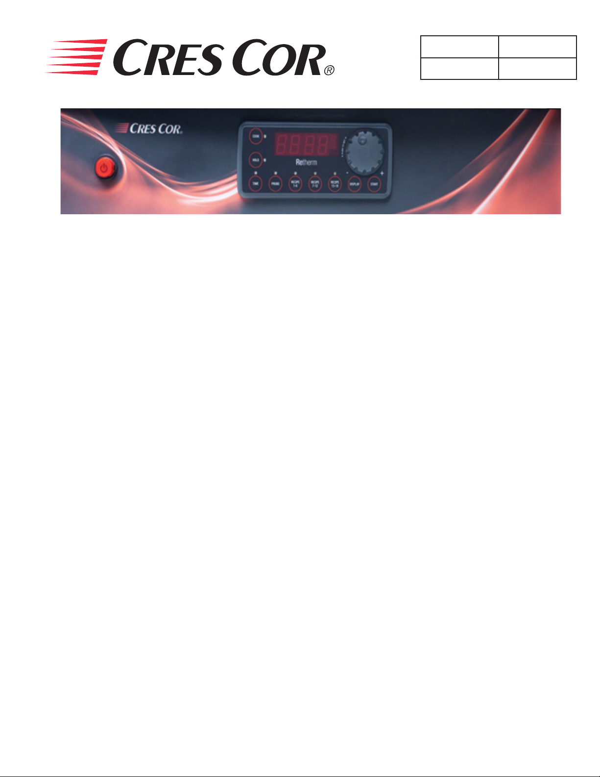
RECIPES:
The control can hold up to 18 saved recipes.
To save a recipe:
1. Press and hold both the TIME button and the knob for
5 seconds. The screen will be ashing. This is the setup
menu.
2. Turn the knob through the menu until you get to “Edit”.
3. Press the knob and turn to the recipe you want to edit.
There are 18 blank recipes to customize and save.
4. Press the knob and enter the cook, hold and time values.
5. After the entering the nal value, “Edit” will show
again.
6. Press the knob to edit more recipes or turn to “End” to
exit the menu.
To use one of the recipes:
1. Push one of the three RECIPE group buttons for the
recipe number you want.
2. Turn the knob to the recipe you want and press the knob
to select.
3. Press the START button to preheat.
4. After it shows “READY”, press the START button
again to begin the recipe.
Note: The display button will cycle through all the values
as before, but will include the recipe number, if
using a saved recipe.
Quick Recipe Note:
You can set “Quick Recipes” for recipes that you use often.
This way, when you press a recipe group button and press
start, that recipe will start cooking without searching
for the recipe number. Recipe numbers can be set up as
“quick recipes” as follows:
1. Press and hold both the TIME button and the knob for 5
seconds to get into the menu.
2. Turn the knob to “RBTN” and press the knob. The word
“PUSH” will ash.
3. Press one of the recipe group buttons to assign a recipe.
Note: Recipe numbers 1-6 can be set up as Group button 1.
Recipe numbers 7-12 can be set up as Group button 2.
Recipe numbers 13-18 can be set up as Group button 3.
4. Turn the knob to the recipe number you want to assign
to that button and press the knob.
Repeat the process to assign recipes to the other two recipe
group buttons; or,
turn the knob to “END” the submenu; turn to “END” the
menu.
Additional Menu Settings:
Press and hold both the TIME button and the knob for 5
seconds to get into the menu.
Here you can set the recipes, quick recipes, temperature
units (°C or °F) and the datalog
settings (USB connection required):
”RECE” allows you to enable or disable the data record
feature.
“RECF” allows you set how often (in minutes) a
datapoint will be recorded.
“RECD” allows you to set how long (in days) you would
like the data to be stored in memory.