Crescendo Fitness 280 User manual

Magnet Power Elliptical Bike
OWNER’S MANUAL
Model #280

1
Table of Contents
1
■
Precautions
2
■
Operating Instruction
3
■
Parts List
4
■
Overview Drawing
5
■
Hardware Packing List
6
■
Assembly Instructions
7
■
Adjustment / Maintenance
and Treatment
8
■
Warm Up Exercises
Attention:
Do not return this product to the store or place of purchase.
If you are missing parts or have any questions about assembly call
Lion Sports Customer Service 1-877-244-5466 between 9am and 4pm EST.
customerservice@lionsportsinc.com

2
1. Precautions
1. Read all the instructions in this manual and do warm up exercises before using this equipment.
Refer to section 8 - Warm Up Exercises. After exercising, relaxation is suggested for
cool-down.
2. This home stationary fitness equipment is an aerobic training tool that, used correctly, can
help you to develop your cardio-vascular function.
3. Please make sure all parts are not damaged and are tight & snug prior to use. The equipment
should be placed on a flat surface when using.
4. On bikes the minimum insert depth mark line could not be left outside of the seat adjustor
when adjusting the height of seat adjustor.
5. Please wear appropriate clothing, including athletic shoes during exercise; do not wear
clothes that might catch on any part of this equipment. If pedal straps are supplied please
make sure that they are tight.
6. Consult your physician prior to any strenuous exercise. This is particularly important to people
who are over 35 years old or who have prior medical history. In order to experience the
maximum result from any exercise it is best to make a regular exercise schedule and stick to
it!
7. Keep children and pets away from the equipment. This machine is designed for adults only.
The minimum free space required for safe operation is 6’ X 8’.
8. Do not use this equipment one hour before or after dinner.
9. If you feel any chest pains, nausea, dizziness, or short of breath, you should stop exercising
immediately and consult your physician before continuing.
10.The maximum weight capacity of the user is 250 lbs.
11.The braking system of the equipment is speed-independent.
Warning: Please follow the above-mentioned precautions.

3
2. Operation Instruction
1) Operate according to your own fitness level.
2) Adjustment of the tension control: Turn the tension control clockwise, the resistance will be
increased, counter clockwise and the resistance will be decreased.
3) If your exercise equipment has a seat, adjust the seat cushion by releasing the round knob,
adjusting the height of seat cushion to a suitable position and tightening the round knob. Sit
on the seat cushion when exercising, do not stand.
4) If your exercise equipment has pedals please tighten the pedal straps and hold the handlebars
with you hands adjusting your posture according to your exercise speed and intensity.
Warning: To avoid injury, do not switch pedaling directions when riding in one direction at
high speed.
SPECIFICATIONS:
TIME……………………………………………00:00 –99:59 MIN
SPEED………………………………………….0 – 999.9 MPH
DISTANCE……………………………………..0 – 99.99 MILES
CALORIES……………………………………..0 – 999.9 KCAL
ODOMETER(if have)……………………….…0 – 99.99 MILES
PULSE(if have)………………………….……..40 –200 BEATS/MIN
KEY FUNTION:
MODE/SELECT: To select the function you want.
SET(if have): To input the target value by the key.
RESET/CLEAR(if have):To let the value reset.
OPERATION PROCEDURES:
AUTO ON/OFF. The monitor will be automatically shut off if there is no signal coming in for 4
minutes, The monitor will be auto-powered when start exercise or press the key.
FUNTION:
(1).TIME(TMR) Auto-memorize the workout time while exercising,
(2).SPEED(SPD) Display the current speed.
(3). DISTANCE(DST) Accumulate the distances while exercising.
(4).CALORIES(CAL) Auto-memorize calories amount consumed while exercising.
(5).ODOMETER(TOTAL) (If equipped) Display the total distances while exercising. When the
signal input, it start the value up on the original data. The ODOMETER can’t be reset (by RESET
key) except you replace battery once.
(6).PULSE(PUL) (if equipped).Display the user’s heart rate per minute while exercising, Remark:
You have to hold on reaction planks with both hands.
BATTERY If the display on the monitor is not easily readable or in not working correctly, please
replace the batteries. This monitor uses two”AA’ batteries. You should replace both batteries at

4
the same time.
3. Parts List
No.
Description
Qty
No.
Description
Qty
1
Main frame
1
30
Left pedal axis
1
2
Rear stabilizer
1
31
Right pedal axis
1
3
Base foot
4
32
Hand pulse tube
2
4
Pedal support tube
2
33
M8×40 Bolt
4
5
Pedal
2
34
M10×70 Bolt
2
6
Pulling pole
2
35
Rear clip bracket
2
7
M10 Nut cap
8
36
M8×16 Bolt
2
8
Left Handlebar
1
37
M8×50 Bolt
4
9
Arc spacer
2
38
M8×20 Bolt
10
10
Computer E-220B
1
39
M5x35 Screw
1
11
Right handlebar
1
40
M8 Cap nut
4
12
Tension control wire
1
41
M10 Lock nut
6
13
Front stabilizer
1
42
M8 Lock nut
6
14
Front upright frame
1
43
1/2”Left lock nut
1
15
Handlebar bushing
4
44
1/2”Right lock nut
1
16
M8 Special washer
2
45
Φ8 Arc washer
12
17
M10 Special washer
6
46
Φ10 Flat washer
9
18
Handlebar support bushing
4
47
Φ16 wave washer
2
19
Pedal bushing
4
48
Φ10 Big washer
2
20
Hand pulse bar
1
49
Φ8 Big washer
2
21
Tension control
1
50
Φ8 Flat washer
10
22
Handlebar foam
2
51
Φ8 Spring washer
16
23
Adjustable base foot
2
52
Φ5 Flat washer
1
24
Hand pulse wire
2
53
Φ8 Plastic flat washer
2
25
Sensor wire
1
54
Pedal axis bushing
2
26
Computer wire
1
55
Crosshead self lock bolt ST4.2x20
8
27
Magnetic bracket
1
56
M6x60 Bolt
1
28
Φ20 Wave washer
2
57
M5x50 Bolt
1

5
29
Ball shape plug
2
58
M5 Nut
2
No.
Description
Qty
No.
Description
Qty
59
M6 Nut
2
80
Φ6 Flat washer
3
60
M10x1x5 Nut
4
81
Crosshead self bolt ST2.9x8
2
61
M10x1x3 Nut
2
82
Special flat washer
2
62
M12 Nut
1
83
Crosshead self bolt ST4x10
8
63
Crosshead self lock bolt ST4.2x16
2
84
M 6x8 Bolt
2
64
Bearing set
1set
85
Wheel axis
2
65
Press-belt wheel
1
86
Wheel
2
66
Φ10 Spacer
1
87
U-shape bracket
2
67
Crank
1
88
Pulse sensor
2
68
Belt
1
89
Round plug
2
69
M10 Nut
1
90
F35x33x14.5 square tube plug
2
70
Press-Wheel bracket
1
91
M10X65 bolt
1
71
Wire clamp
1
92
Crosshead self bolt ST4x25
2
72
Left cover
1
93
M8x16 bolt
2
73
Belt wheel
1
94
M10x55 Bolt
2
74
Right cover
1
95
M6 lock nut
1
75
Press-Wheel bracket spring
1
96
Wrench
1
76
Magnetic spring
1
97
Screw driver(s=5)
1
77
Securing bracket
2
98
Power support pole
1
78
Magnet axis
1
99
Wrench
1
79
Flywheel
1
6
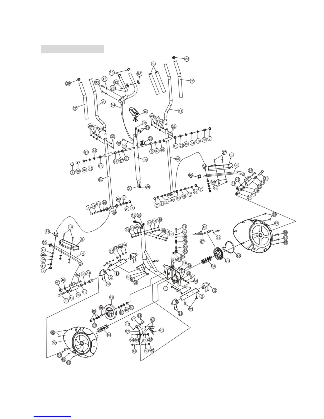
4. Overview Drawing
7
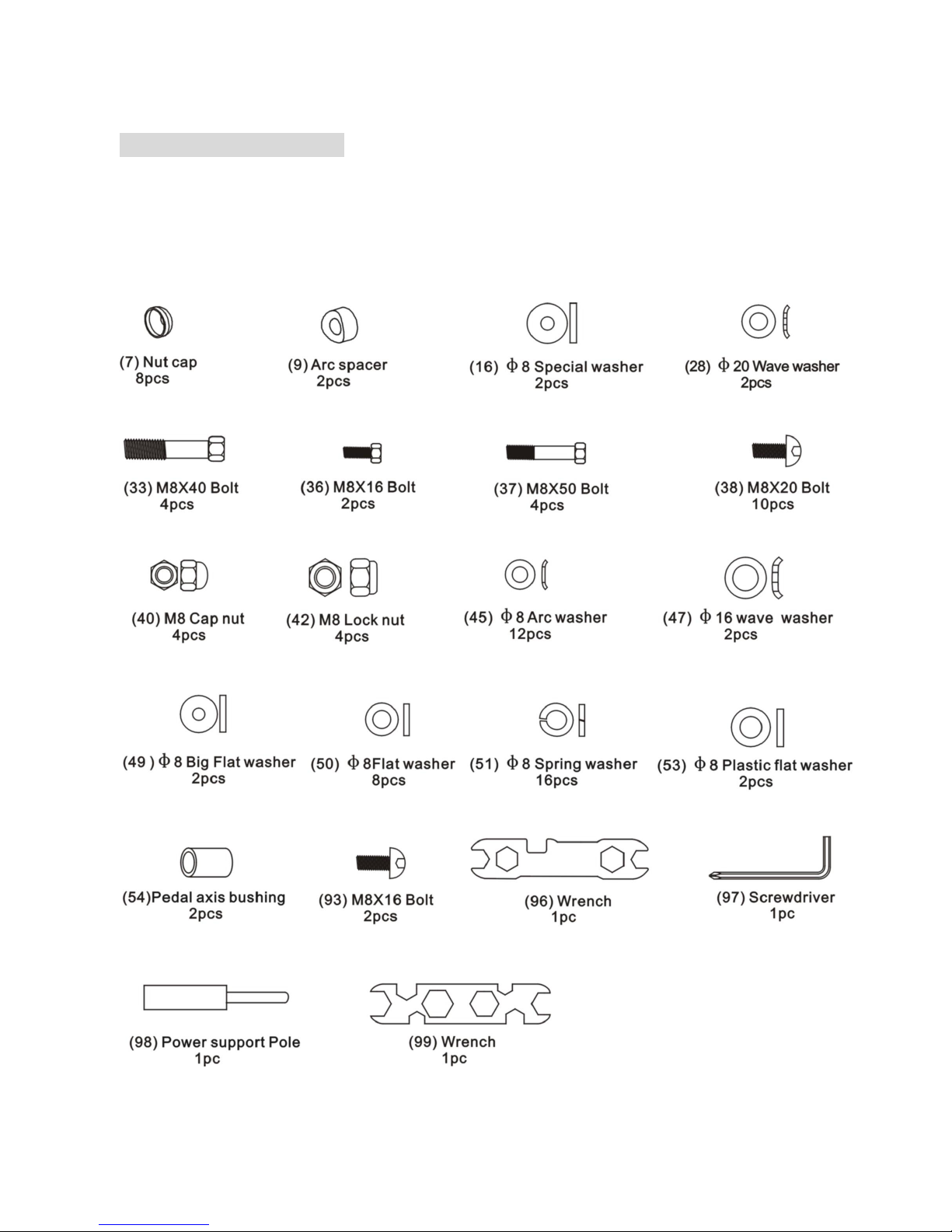
5. Hardware Packing List
In order to make your assembling work much easier, we list the hardware and tools that you would use
during the assembling period as bellows:

8
6. Assembly Instructions
Attention:
Please follow these assembly instructions step by step to
assemble this elliptical.
1. Install the Rear Stabilizer
Attach the Rear stabilizer (2) to the Main frame (1) with two
Bolts (38), spring washers (51), and Flat washers (50).
(Refer figure 1)
2. Install the Front Stabilizer
Attach the Front stabilizer (13) to the Main Frame (1) with two
Bolts (38), spring washers (51), and Flat washers (50). (Refer
figure 2)
3. Install the Front Upright Frame
1. Put the end of resistance cable into the spring
hook of Tension control wire (12) as shown on
drawing A of figure 3
2. Pull the resistance cable up and force it into the
gap of metal bracket of Tension control wire (12)
as shown on drawing Bof figure3
3. Connect the resistance cable with the Tension
control wire (12) completed as shown on
drawing Cof figure 3
4. Connect the computer wire (26) to the Sensor wire (25) coming out from mainframe
(1).
5. Insert the Front upright frame (14) to the main frame (1) and secure it with six pcs of
Bolts (38), Spring washers (51), and Arc washers (45) as shown on drawing Dof
figure 3.

9
4. Install the Hand Pulse Bar
a. Insert the hand pulse wires (24) from hand pulse bar (20) into the hole on the back of Front
upright frame (14) and then pull them out from the upper hole of Front upright frame (14).
b. Attach the hand pulse bar (20) to the groove of Front upright frame (14) with two pcs of arch
spacers (45), and bolts (93). (Refer figure 4)
5. Install the Computer
Insert the Pulse wires (24) and Computer wire(26) to the holes on the back of the Computer (10).
Attach the Computer (10) to the top of the Front upright frame (14). (Refer figure 5)
6. Install the Handlebar Support (Right & Left)
a. Attach one Arc spacers (9) and Wave washer (47) to
the right end of horizontal axle of Front upright frame
(14).
b. Insert right Handlebar support (6R) to the right end of
horizontal axle of Front upright frame (14) and secure
it with one Plastic flat washer (53), Big washer (49),
spring washer (51), Special washer (16), and Bolt
(36).
c. After assembled the Nut cap (7) to the Bolt (36), the
right Handlebar support (6R) can move freely.
d. Do the same steps as the above to assemble the left
Handlebar support (6L). (Refer figure 6)
7. Install the Pedal Support Tube (Left & Right)
Insert the left Pedal support tube (4) through the Rear
U-shape bracket (35), a Wave washer (28) and Pedal
axis bushing (54) into the Left pedal axis (30). And then
attach the pedal axis (30) to the crank (67) and tighten them with Power support pole (98) and
then lock the left lock nut (43).
Do the same steps as above to assemble the right Pedal support tube (4) to the right pedal axis
10
(31). (Refer figure 7)
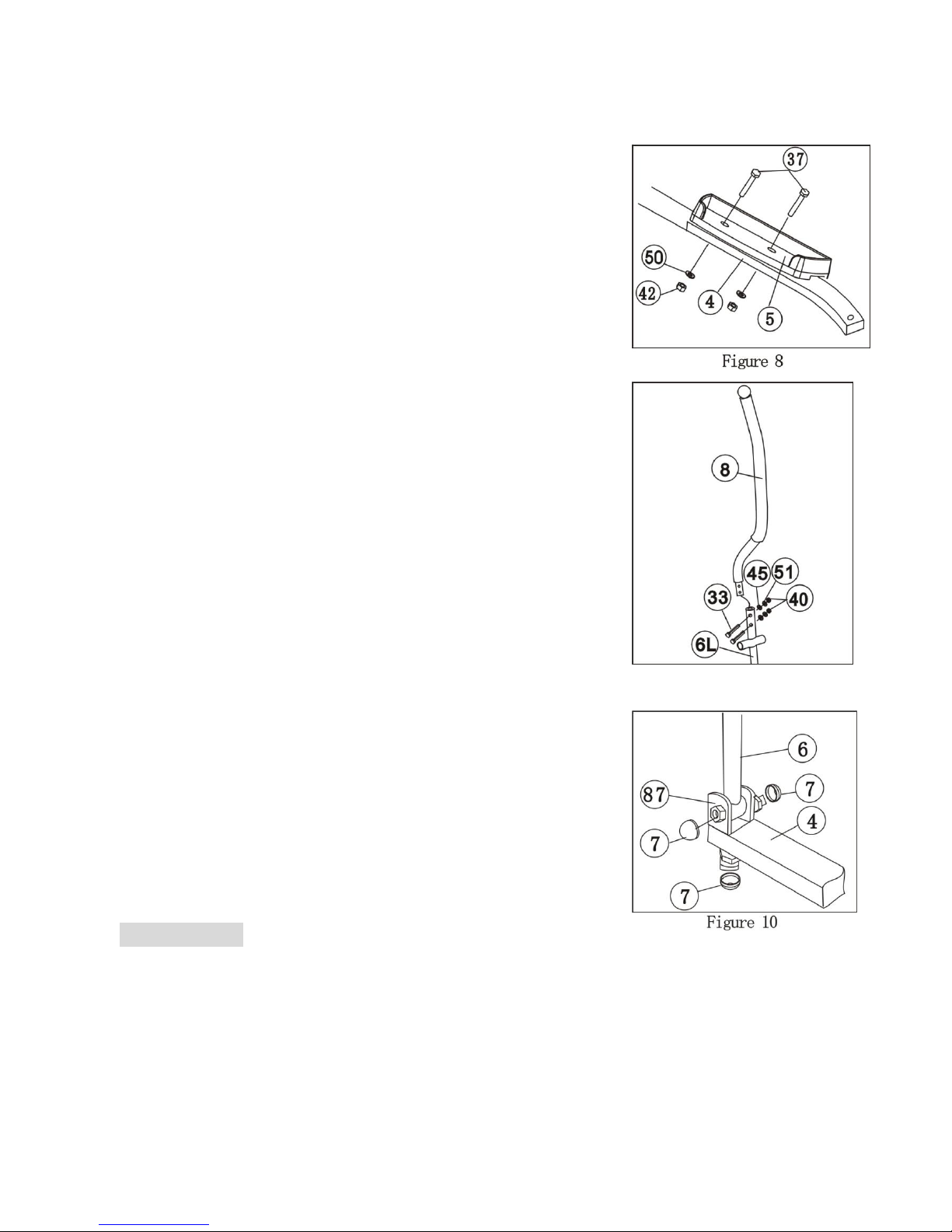
8. Install the Pedals
Attach the left Pedal (5) to the left Pedal support tube (4) with
four M8x50 Bolts (37), Flat washers (50), and M8 Lock nuts (42).
Do the same steps as above to assemble the right Pedal (5) to
the right Pedal support tube (4). (Refer figure 8)
9. Install the Handlebar (Left & Right)
Insert the Left handlebar (8) to the Left Handlebar support (6L)
with four M8x40 Bolts (33), Arc washers (45), Spring washers
(51), and M8 Cap nuts (40). Do the above same steps to
assemble the Left handlebar (8) to the right Handlebar support
(6R). (Refer figure 9)
Note: The bolt must be set into the hexangular hole.
10. Install the nut cap
After installed and adjusted the equipment, clip on the cap nut s
at the connecting of U-shape brackets (87) and Handlebar
supports (6), (Refer Figure 10)
7. Adjustment
1) Resistance can be adjusted by tension control to increase or decrease the exercise intensity.
2) Seat height, back and forth positions can be adjusted by the long and short knobs.
3) After a long-term use, the turning parts may be loose, please tighten the bolts or screws
following the instruction of the engineman.

11
7. Maintenance and Treatment
1) Verify that all the bolts and nuts are locked properly and the turning parts should be turned
freely without damaged parts.
2) Clean the equipment with soap and slightly damp cloth only. Please do not use any solvent to
clean the equipment.
Malfunctions and treatment
Malfunction
Reason
Treatment
Base frame is unstable
1. Floor is not flat or there is
Small object under the front or
Rear stabilizer.
2. The front and rear base feet
have not been leveled when
assembling.
1. Remove the object.
2. Adjust the front and rear
stabilizers.
Handlebar or seat
cushion is shaking.
The screw loose.
Tighten the screws.
Loud noise from the
moving parts.
The interval of the parts has not
been tightened correctly.
Open the covers to check.
No resistance when
using the
equipment.
1.The interval of the magnetic
resistance increases.
2.Tensioncontrolisdamaged.
3. Runningbeltisslip.
1. Open the covers to check.
2. Replace the Tension control.
3. Open the covers to check.

12
8. Warm Up Exercises
A successful exercise program consists of a warm-up, aerobic exercise, and a cool-down. Do the
entire program at least two and preferably three times a week, resting for a day between
workouts.After several months, you can increase your workouts to four or five times per week.
Warm-up is an important part of your workout, and should begin every session. It prepares your
body for more strenuous exercise by heating up and stretching your muscles, increasing your
circulation, pulse rate, and helps to deliver more oxygen to your muscles. At the end of your
workout, repeat these exercises to reduce the possibility of sore muscles. We suggest the
following warm-up and cool-down exercises:
Inner Thigh Stretch
Sit with the soles of your feet together with your knees pointing
outward. Pull your feet as close into your groin as possible. Gently
push your knees towards the floor. Hold for 15 counts.
Hamstring Stretch
Sit with your right leg extended. Rest the sole
of your left foot against your right inner thigh.
Stretch toward your toe as far as possible.
Hold for 15 counts. Relax and then repeat with
left leg extended.
Head Roll
Rotate your head to the right for one count, feeling
the stretch up the left side of your neck. Next, rotate
your head back for one count, stretching your chin to
the ceiling and letting your mouth open. Rotate your
head to the left for one count, and finally, drop your
head to your chest for one count.
Shoulder Lift
Lift your right shoulder up toward your ear for
one count. Then lift your left shoulder up for
one count as you lower your right shoulder.

13
Calf-Achilles Stretch
Lean against a wall with your left leg in front of the right
and your arms forward. Keep your right leg straight and
the left foot on the floor; then bend the left leg and lean
forward by moving your hips toward the wall. Hold, then
repeat on the other side for 15 counts.
Toe Touch
Slowly bend forward from your waist, letting
your back and shoulders relax as you stretch
toward your toes. Reach down as far as you
can and hold for 15 counts.
Side Stretch
Open your arms to the side and continue lifting them
until they are over your head. Reach your right arm
as far upward toward the ceiling as you can for one
count. Feel the stretch up your right side. Repeat this
action with your left arm.

14
Limited Warranty
This product is warranted to be free of defects in workmanship or materials from the time
of purchase for a period of 90 days.
Should evidence of defects in materials or workmanship appear within the 90 day limited
warranty period after the date of purchase, Lion Sports Inc. will either repair or replace the
defective part at its option. This limited warranty covers normal consumer usage. This
limited warranty does not cover institutional or commercial use and does not cover
failures which result from alterations, accidents, misuse, abuse neglect or acts of God.
Do not return this product to the store or place of purchase as they are not equipped to
handle repairs. All warranty or repair requests require a return authorization number
issued by Lion Sports Inc.
Proof of purchase or other proof of the date of purchase is required. Requests for
warranty service can be made at 1-877-244-5466 between the hours of 9am and 4pm EST
or via the internet at customerservice@lionsportsinc.com
This warranty gives you specific legal right and you may have other rights which vary from
state to state.
Thank you for purchasing this quality Crescendo Fitness Product.
Crescendo Fitness is a registered Trademark of

15
Lion Sports Inc.
701 Koehler Ave. Ste 2
Ronkonkoma, NY 11779
Toll Free Customer Service Hotline –1-877-244-5466
Or customerservice@lionsportsinc.com
FOR MORE INFORMATION ON THE heavyhands EXERCISE SYSTEM
VISIT www.heavyhandsfitness.com
Table of contents
Popular Elliptical Trainer manuals by other brands

Horizon Fitness
Horizon Fitness CE9.2 owner's manual

NordicTrack
NordicTrack Audiostrider Cx650 Elliptical Gebruiksaanwijzing

Precor
Precor Move Beyond EFX556 NAVY owner's manual

Weslo
Weslo Momentum 220x Elliptical Manuel de l'utilisateur

Vision Fitness
Vision Fitness XF40 owner's manual

NordicTrack
NordicTrack E11.0 Elliptical Manual do utilizador


