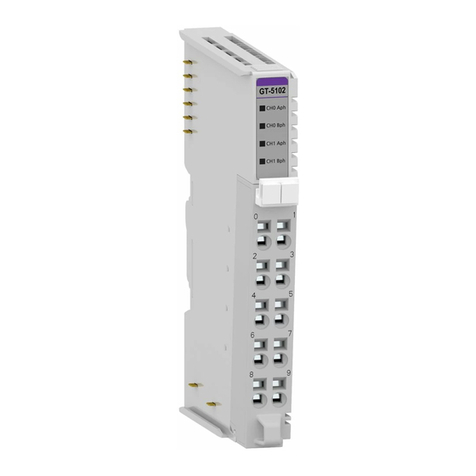
CREVIS GT-5521 User manual

1Stepping Motor Driver FnIO G-Series
Copyright(C) CREVIS Co.,Ltd Support +82-31-899-4599 URL: www.crevis.co.kr
Version 1.00
2020 CREVIS Co.,Ltd
GT-5521
Special IO Module
User Manual

2Stepping Motor Driver FnIO G-Series
Copyright(C) CREVIS Co.,Ltd Support +82-31-899-4599 URL: www.crevis.co.kr
DOCUMENT CHANGE SUMMARY
REV
PAGE
REMARKS
DATE
EDITOR
1.00
New Document
2020/07/31
CH HONG

3Stepping Motor Driver FnIO G-Series
Copyright(C) CREVIS Co.,Ltd Support +82-31-899-4599 URL: www.crevis.co.kr
Table of Contents
1. Important Notes........................................................................................................................................ 4
1.1. Safety Instruction...............................................................................................................................5
1.1.1. Symbols..................................................................................................................................... 5
1.1.2. Safety Notes...............................................................................................................................5
1.1.3. Certification................................................................................................................................ 5
2. Specification............................................................................................................................................. 6
2.1. GT-5521.............................................................................................................................................6
2.1.1. Wiring Diagram............................................................................................................................ 6
2.1.2. LED Indicator............................................................................................................................... 7
2.1.3. Specification.................................................................................................................................8
2.1.4. Environment Specification........................................................................................................... 9
2.1.5. Function Command....................................................................................................................10
2.1.6. Configuration Parameter Data.................................................................................................... 11
2.1.7. Mapping data into the image table............................................................................................. 13
3. How to use position table function.......................................................................................................... 25
4. Dimension...............................................................................................................................................29
4.1. GT-5521...............................................................................................................................................29
5. Mounting................................................................................................................................................. 30
5.1 I/O Inserting and Removing Devices.................................................................................................. 30
5.2 RTB (Removable Terminal Block)...................................................................................................... 31
6. G-Bus Pin Description.............................................................................................................................32
APPENDIX A.................................................................................................................................................. 33
A.1 Product List.......................................................................................................................................... 33
A.2. Glossary.............................................................................................................................................. 35

4Stepping Motor Driver FnIO G-Series
Copyright(C) CREVIS Co.,Ltd Support +82-31-899-4599 URL: www.crevis.co.kr
1. Important Notes
Solid state equipment has operational characteristics differing from those of electromechanical equipment.
Safety Guidelines for the Application, Installation and Maintenance of Solid State Controls describes some
important differences between solid state equipment and hard-wired electromechanical devices.
Because of this difference, and also because of the wide variety of uses for solid state equipment, all
persons responsible for applying this equipment must satisfy themselves that each intended application of
this equipment is acceptable.
In no event will CREVIS be responsible or liable for indirect or consequential damages resulting from the use
or application of this equipment.
The examples and diagrams in this manual are included solely for illustrative purposes. Because of the
many variables and requirements associated with any particular installation, CREVIS cannot assume
responsibility or liability for actual use based on the examples and diagrams.
If you don't follow the directions, it could cause a personal injury, damage to the equipmentor
explosion
Do not assemble the products and wire with power applied to the system. Else it may cause an electric arc,
which can result into unexpected and potentially dangerous action by field devices. Arching is explosion risk
in hazardous locations. Be sure that the area is non-hazardous or remove system power appropriately
before assembling or wiring the modules.
Do not touch any terminal blocks or IO modules when system is running. Else it may cause the unit to an
electric shock or malfunction.
Keep away from the strange metallic materials not related to the unit and wiring works should be controlled
by the electric expert engineer. Else it may cause the unit to a fire, electric shock or malfunction
If you disobey the instructions, there may be possibility of personal injury, damage to equipment or
explosion. Please follow below Instructions.
Check the rated voltage and terminal array before wiring. Avoid the circumstances over 50℃of
temperature. Avoid placing it directly in the sunlight.
Avoid the place under circumstances over 85% of humidity.
Do not place Modules near by the inflammable material. Else it may cause a fire.
Do not permit any vibration approaching it directly.
Go through module specification carefully, ensure inputs, output connections are made with the
specifications. Use standard cables for wiring.
Use Product under pollution degree 2 environment.
Warning!
Caution!

5Stepping Motor Driver FnIO G-Series
Copyright(C) CREVIS Co.,Ltd Support +82-31-899-4599 URL: www.crevis.co.kr
1.1. Safety Instruction
1.1.1. Symbols
1.1.2. Safety Notes
The modules are equipped with electronic components that may be destroyed by
electrostatic discharge. When handling the modules, ensure that the environment (persons,
workplace and packing) is well grounded. Avoid touching conductive components, RBUS
Pin.
1.1.3. Certification
c-UL-us UL Listed Industrial Control Equipment, certified for U.S. and Canada
See UL File E235505
CE Certificate
EN 61000-6-2; Industrial Immunity
EN 61000-6-4; Industrial Emissions
Reach, RoHS (EU, CHINA)
Identifies information about practices or circumstances that can cause an
explosion in a hazardous environment, which may lead to personal injury or
death property damage, or economic loss
Identifies information that is critical for successful application and understanding of the
product
Identifies information about practices or circumstances that can lead to personal
injury, property damage, or economic loss.
Attentions help you to identity a hazard, avoid a hazard, and recognize the
consequences

6Stepping Motor Driver FnIO G-Series
Copyright(C) CREVIS Co.,Ltd Support +82-31-899-4599 URL: www.crevis.co.kr
2. Specification
2.1. GT-5521
2.1.1. Wiring Diagram
Pin No.
Signal Description
Signal Description
Pin No.
0
Motor Out1_A
Motor Out2_A\
1
2
Motor Out1_B
Motor Out2_B\
3
4
Input Channel 0
Input Channel 1
5
Digital Input
Encoder Mode
Digital Input
Encoder Mode
DI0
Enc Aph
DI1
Enc Bph
6
Input Channel 2
Input Channel 3
7
Digital Input
Encoder Mode
Digital Input
Encoder Mode
*Hard Stop
*Hard Stop
8
Field Power 24V
Field Power 0V
9
Warning : Do not connect or disconnect a motor while the driver is energized.
*Hard Stop : Stop motor when input is detected

7Stepping Motor Driver FnIO G-Series
Copyright(C) CREVIS Co.,Ltd Support +82-31-899-4599 URL: www.crevis.co.kr
2.1.2. LED Indicator
Module Win. Label
LED
Color
Status
Description
RUN
Green
Off
Module supply not connected.
Blinking
Motor is at constant speed. Absolute positioning or mo
tion command is under execution.
On
Motor Normal Operation.
AL *
Green
On
Alarm occurred.
Off
No Alarm.
CCW
Green
On
Motor is rotating counter clockwise.
Off
Motor is stopped.
CW
Green
On
Motor is rotating clockwise.
Off
Motor is stopped.
IN 0
Green
On
Input 0 is ON.
Off
Input 0 is OFF.
IN1
Green
On
Input 1 is ON.
Off
Input 1 is OFF.
IN2
Green
On
Input 2 is ON.
Off
Input 2 is OFF.
IN3
Green
On
Input 3 is ON.
Off
Input 3 is OFF.
*Note : At least one of the following conditions occurs:
•Over Voltage, Under Voltage, Over Current detection

8Stepping Motor Driver FnIO G-Series
Copyright(C) CREVIS Co.,Ltd Support +82-31-899-4599 URL: www.crevis.co.kr
2.1.3. Specification
Items
Specification
Digital input
Number of channel
4 points, sink type
(2 points DI or Encoder Input, 2 point *Hard Stop Input)
Indicators
4 green terminal Input status
On–state voltage
24Vdc nominal
12V~28.8V @ 60℃
On-state current
6.4mA @ 28.8Vdc
Off-state voltage
5Vdc @ 25℃
Input signal delay
OFF to ON : Max. 0.3ms
ON to OFF : Max. 0.3ms
Nominal input impedance
5.4K ohm typical
Encoder mode
Incremental encoder support
General specification
Power dissipation
Max. 100mA @ 5Vdc
Isolation
I/O to Logic : photocoupler isolation
Field power : non-isolation
UL field power
Supply voltage : 24Vdc nominal, Class 2
Field power
Supply voltage : 24Vdc nominal
Voltage range : 18~28.8Vdc,
Power dissipation : Max. 35mA @ 24Vdc
Wiring
I/O Cable Max. 2.0mm2(AWG 14)
Torque
0.8Nm(7 lb-in)
Weight
60g
Module size
12mm x 99mm x 70mm,
Environment condition
Refer to ‘Environment Specification’
*Hard Stop : Stop motor when input is detected
Items
Specification
Stepper motor driver power element
Amount
1 stepper motor
Load type
2-phase bi-polar motor
Rated voltage
24Vdc nominal
18Vdc ~ 28.8Vdc
Output current
Max. 1A @-40℃~ 60℃
Step resolution
Max. 16 microstepping

9Stepping Motor Driver FnIO G-Series
Copyright(C) CREVIS Co.,Ltd Support +82-31-899-4599 URL: www.crevis.co.kr
- full, half, 1/4, 1/8, 1/16
Operation modes
Instant Command Mode
Position Table Mode
Function modes
Position(absolute/relative),
Set Point Change, etc.
Protection
Over current / Over voltage
Reverse voltage protection
2.1.4. Environment Specification
Environmental specification
Operation Temperature
-40℃~60℃
UL Temperature
-20℃~60℃
Storage Temperature
-40℃~85℃
Relative Humidity
5%~90% Non-condensing
Mounting
DIN Rail
General specification
Shock Operating
IEC 60068-2-27
Vibration Resistance
Based on IEC 60068-2-6
DNVGL-CG-0039 : Vibration Class B, 4g
Industrial Emissions
EN61000-6-4/All : 2011
Industrial Immunity
EN 61000-6-2 : 2005
Installation Position
Vertical and horizontal installation is available
Product Certifications
CE, UL, FCC

10 Stepping Motor Driver FnIO G-Series
Copyright(C) CREVIS Co.,Ltd Support +82-31-899-4599 URL: www.crevis.co.kr
2.1.5. Function Command
GT-5521 provides two main function commands.
After power on, module will be ready and motor is neutral position(not stopped).
Usually, GT-5521 is on 'Instant Command mode' which is activate function command from master(➊).
If function command(from master) of GT-5521 is done(➋), GT-5521 is stay last command status and
hold on position(➌).
Ex)
In 'Position Table Mode', module needs some specific commands. In this manual, it will be covered in t
he 'How to use position table function.' chapter.

11 Stepping Motor Driver FnIO G-Series
Copyright(C) CREVIS Co.,Ltd Support +82-31-899-4599 URL: www.crevis.co.kr
2.1.6. Configuration Parameter Data
This section describes the individual parameters that shall be used to configure the GT-5521 Stepper modu
le:
* Float type :
ex) Maximum speed = 2008.16 step/sec
Configuration parameter of Maximum speed = 200816 → 0x31070

12 Stepping Motor Driver FnIO G-Series
Copyright(C) CREVIS Co.,Ltd Support +82-31-899-4599 URL: www.crevis.co.kr
-When changing the parameter data, set the motor operation to high impedance status.
(*) WH: writable only when outputs are in high impedance
•*M_DIR : Last State in Motor Direction(Reverse[0], Forward[1])
•*CMD_STATUS : Commend Success(0), Commend Error(1), Commend Busy(2)
•*MOT_STATUS : Stop(0), Accelerate(1), Decelerate(2), Constant Speed(3)
•This counter is a cyclic 16-bit counter. The relationship between this counter and the internal position
counter depends on the resolution of the encoder and the microsteps defined for the internal position
count
•The absolute position value range is -0x001F FFFF to 0xFFE0 0000.

13 Stepping Motor Driver FnIO G-Series
Copyright(C) CREVIS Co.,Ltd Support +82-31-899-4599 URL: www.crevis.co.kr
2.1.7. Mapping data into the image table
Input Image Value - 16Byte
*M_DIR : Last State in Motor Direction(Reverse[0], Forward[1])
*CMD_STATUS : Commend Success(0), Commend Error(1), Commend Busy(2)
*MOT_STATUS : Stop(0), Accelerate(1), Decelerate(2), Constant Speed(3)
This counter is a cyclic 16-bit counter. The relationship between this counter and the internal position counter
depends on the resolution of the encoder and the microsteps defined for the internal position count
The absolute position value range is -0x001F FFFF to 0xFFE0 0000.

14 Stepping Motor Driver FnIO G-Series
Copyright(C) CREVIS Co.,Ltd Support +82-31-899-4599 URL: www.crevis.co.kr
Output Image Value - 10Byte
* INPUT_QUERY, GOTO_INDEX is only for 'Position Table Function'.
* 'State Change' is only for INPUT_QUERY.
* 'Position Table No.' is only for GOTO_INDEX.
- Since the initial state of the motor is in the high impedance state, it is recommended to change to the STO
P operation state before other operations.
- Position Table Index is only for 'Position Table Function'.

15 Stepping Motor Driver FnIO G-Series
Copyright(C) CREVIS Co.,Ltd Support +82-31-899-4599 URL: www.crevis.co.kr
Application Commands
This section describes the output command modes and individual commands of the stepper module in detail.
GT-5521 has two main output mode. 'Instant command mode' and 'Position Table Mode'. It executes only o
ne module output mode at once.
Following table summarizes the list of module output modes:
1. Mode: Instant Command
Description: With this mode, module instantly execute the command, which is received from Network Adpat
er.
Following table summarizes the list of supported commands:
Command: NOP
Description: No action is taken by the module. If this command use in position table function command, it wi
ll be used as wait command.
Command Structure:
Example Command Code :
Command: Set Home Position
Description: This command resets the internal position register to zero. The zero position is also defined as
HOME position.
With Encoder Interface mode, this command initialize encoder count.

16 Stepping Motor Driver FnIO G-Series
Copyright(C) CREVIS Co.,Ltd Support +82-31-899-4599 URL: www.crevis.co.kr
Command Structure:
Example Command Code :
Command: Set Mark Position
Description: This command sets the new value for the mark position.
Command Structure:
Example Command Code : Set Marked Position 200 step
Command: GOTO
Description: This command produces a motion to the specified Home / Mark / Absolute position through the
shortest path. The Absolute position (output scan) value is always in agreement with the selected step mode;
the parameter value unit is equal to the selected step mode (full, half, quarter etc.).
This command keeps the BUSY flag low until the target position is reached. This command can be given onl
y when the previous motion command has been completed (BUSY flag released). Any attempt to perform thi
s command when a previous command is under execution (BUSY low) causes the command to be ignored.

17 Stepping Motor Driver FnIO G-Series
Copyright(C) CREVIS Co.,Ltd Support +82-31-899-4599 URL: www.crevis.co.kr
Command Structure:
Example Command Code : Goto Home/Go to Set/Go to Abs 51,200 steps
Command: GOTO_DP
Description: This command produces a motion to the specified absolute position imposing a forward or a re
verse direction. The Absolute Position (output scan) value is always in agreement with the selected step mo
de; the parameter value unit is equal to the selected step mode (full, half, quarter, etc.).
This command keeps the BUSY flag low until the target speed is reached. This command can be given only
when the previous motion command has been completed (BUSY flag released). Any attempt to perform this
command when a previous command is under execution (BUSY low) causes the command to be ignored.
Command Structure:
Example Command Code : Goto DP Forward / Goto DP Reverse

18 Stepping Motor Driver FnIO G-Series
Copyright(C) CREVIS Co.,Ltd Support +82-31-899-4599 URL: www.crevis.co.kr
* Caution : GOTO DP command has direction of motor movement. Thus, motor doesn't work the shortest wa
y to desired position(in absolute position).
Command: MOVE
Description: This command produces a motion of ‘N’ micro steps specified by the third parameter; the dire
ction is specified by the first parameter (forward or reverse). The value of ‘N’ is always in agreement with th
e selected step mode (full, half, quarter, etc.).
This command keeps the module BUSY until the target number of steps are performed. This command can
only be performed when the motor is stopped. If a motion is in progress, the motor must be stopped and it is
then possible to perform a Move command. Any attempt to perform a Move command when the motor is run
ning causes the command to be ignored.
Command Structure:
Note:
If the specified speed is lower than the configured Minimum Speed than the motor attains the target speed st
arting from zero to allow smooth operation of the motor.

19 Stepping Motor Driver FnIO G-Series
Copyright(C) CREVIS Co.,Ltd Support +82-31-899-4599 URL: www.crevis.co.kr
Example Command Code : Move Forward 51,200 step / Move Reverse 51,200 step
Command: RUN
Description: This command produces a motion at the speed specified by the third parameter; the direction i
s specified by the first parameter (forward or reverse). The value of speed is expressed in steps/sec. The sp
ecified speed value should be lower than Maximum Speed and greater than Minimum Speed (provided in mo
dule configuration) otherwise the Run command is executed at Maximum Speed or Minimum Speed respecti
vely.
This command keeps the module BUSY until the target speed is reached. This command can be given anyti
me and is immediately executed.
Note:
If the specified speed is lower than the configured Minimum Speed than the motor attains the target speed st
arting from zero to allow smooth operation of the motor.
Command Structure:
Example Command Code : Run Forward 1,000 step per sec / Run Reverse 1,000 step per sec

20 Stepping Motor Driver FnIO G-Series
Copyright(C) CREVIS Co.,Ltd Support +82-31-899-4599 URL: www.crevis.co.kr
Command: INPUT_QUERY
Description: This Command is not executed in instant command mode, it is only for Position table function c
ommand.
'INPUT_QUERY' function is that check the change of input channel status. If input channel's condition is as s
ame as user-defined condition, module proceed next position table function. If it is not, stay until it is satisfyin
g.
Command Structure:
Example Command Code :
1. Index 6 : Digital Input Ch1 On → Off?
2. Index 4 : Digital Input Ch2 Off → On?
Command: STOP
Description: This command causes the motor to stop. The first parameter specifies the stop method to be u
sed with this command and it can be either with infinite deceleration (Hard stop) or immediate deceleration to
zero speed and a consequent motor stop (Soft stop)
This command can be given anytime and is immediately executed. This command keeps the module BUSY
until the motor is stopped.
Command Structure:
Table of contents
Other CREVIS Control Unit manuals
