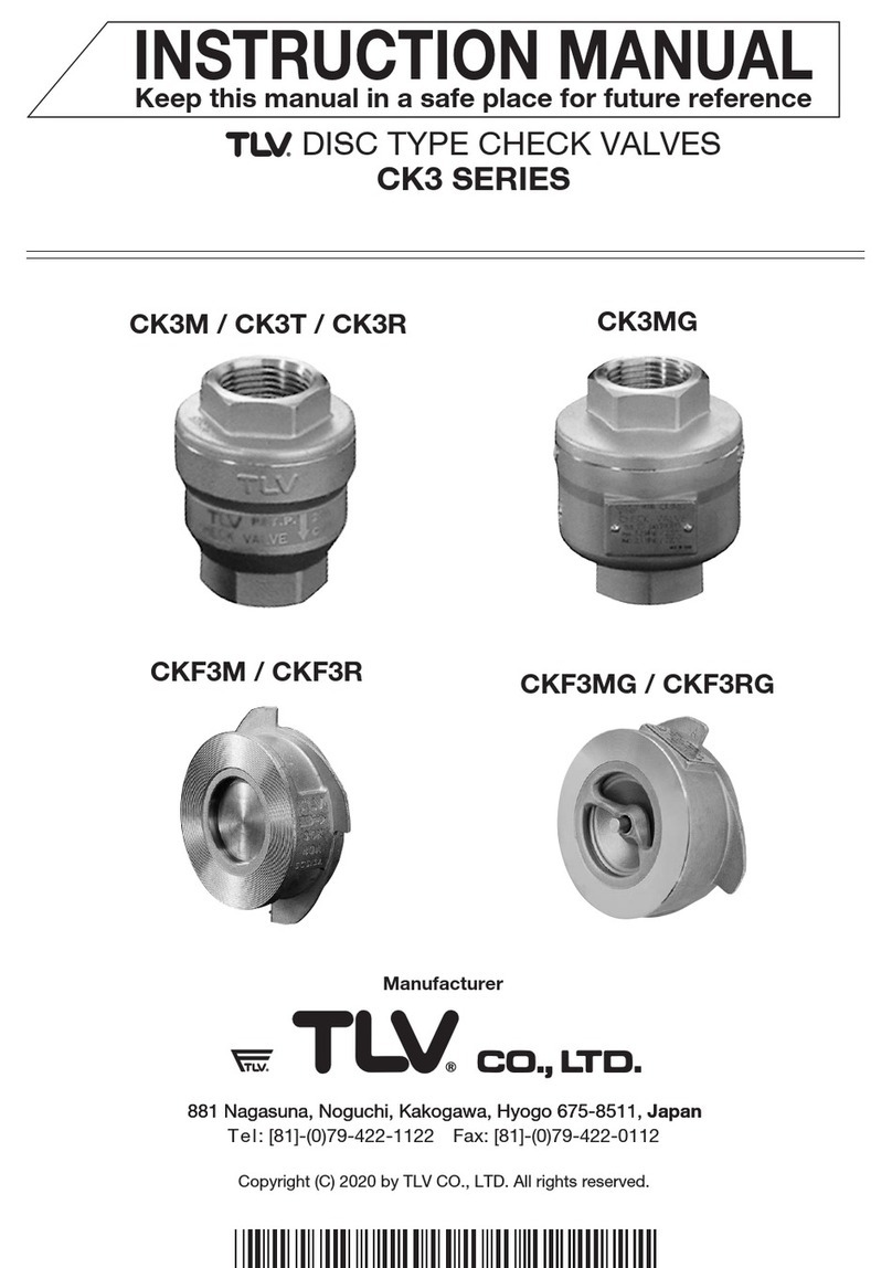
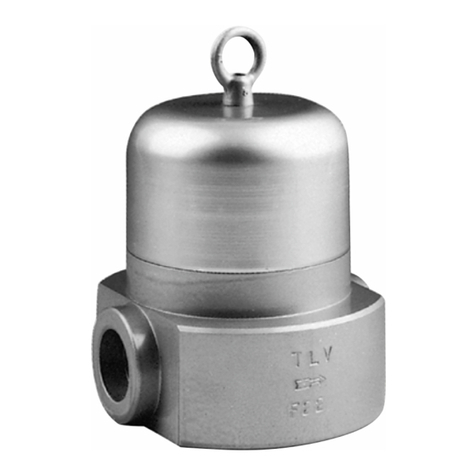
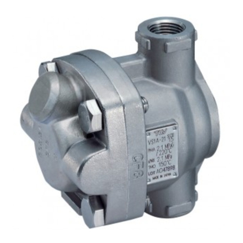
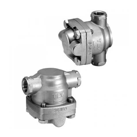
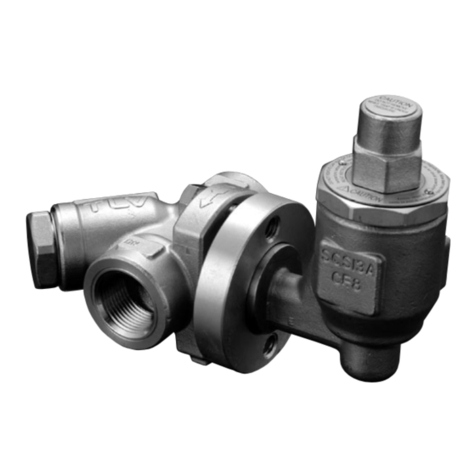
TLV LV6-HC User manual

Copyright (C) 2023 by TLV CO., LTD. All rights reserved.
Clean Steam Trap
LV6-CE/LV6-SF/LV6-P/LV6-EP
LV6-HC/LV6-HS/LV6-HP/LV6-HE
STEAM TRAPS
LV6 SERIES
LV6 SERIE
ÉQUILIBRÉE GAMME LV6
LV6 系列
INSTRUCTION MANUAL
Keep this manual in a safe place for future reference
EINBAU- UND BETRIEBSANLEITUNG
Gebrauchsanleitung leicht zugänglich aufbewahren
MANUEL D UTILISATION
Conserver ce manuel dans un endroit facile d'accès
操作说明书
请务必妥善保管此说明书,以备日后使用。
BALANCED PRESSURE THERMOSTATIC
THERMISCHE KAPSEL-KONDENSATABLEITER
PURGEURS THERMOSTATIQUES À PRESSION
洁净型蒸汽疏水阀
Deutsch
Français
English
中 文

Before beginning installation or maintenance, please read this manual to ensure correct use of the
product. Keep the manual in a safe place for future reference.
The LV6 clean steam traps can be used without adjustment for medium capacity applications up
to 0.6 MPaG (85 psig). They are suitable for steam-using equipment that discharges condensate
at temperatures slightly below saturation temperature and requiring high levels of sanitation such
as medical sterilizers and food process equipment.
1 MPa = 10.197 kg/cm2, 1 bar = 0.1 MPa
For products with special specifications or with options not included in this manual, contact TLV
for instructions.
The contents of this manual are subject to change without notice.
Bitte lesen Sie die Betriebsanleitung vor Einbau und Inbetriebnahme sorgfältig durch und
bewahren Sie sie für späteren Gebrauch an einem leicht zugänglichen Ort auf.
Die thermischen Kondensatableiter der Serie LV6 für Sterilbereiche können ohne besondere
Druckeinstellung für mittlere Durchsatzleistungen und Betriebsdrücke bis 6 bar ü eingesetzt
werden. Sie eignen sich besonders für Anwendungen, bei denen Kondensat mit geringer
Unterkühlung unter Sattdampftemperatur abgeleitet werden soll, z. B. Reaktoren,
Sterilisierapparate und Rohrleitungen.
1 bar = 0,1 MPa
Wenden Sie sich an TLV für Sonderausführungen, die nicht in dieser Einbau- und
Betriebsanleitung enthalten sind.
Wir behalten uns vor, den Inhalt dieser Betriebsanleitung ohne Ankündigung zu ändern.
Einführung
Veuillez lire attentivement ce manuel afin d’utiliser correctement le produit. Nous vous
recommandons de le garder dans un endroit sûr pour de futures consultations.
Les purgeurs thermostatiques de vapeur pure et propre de la gamme LV6 peuvent être utilisés
sans réglage sur des applications de capacité moyenne, jusqu'à une pression de 6 bar. Ces
modèles conviennent aux installations de chauffage évacuant le condensât à une température
légèrement inférieure à la température de saturation, telles les réacteurs, stérilisateurs et lignes de
distribution.
1 bar = 0,1 MPa
Pour tout produit aux spécifications particulières ou comportant des options non reprises dans
ce manuel, veuillez contacter TLV.
Le contenu de ce manuel est sujet à modifications sans préavis.
Introduction
Introduction
Deutsch
Français
English
1

1. Safety Considerations
• Read this section carefully before use and be sure to follow the instructions.
• Installation, inspection, maintenance, repairs, disassembly, adjustment and valve
opening/closing should be carried out only by trained maintenance personnel.
• The precautions listed in this manual are designed to ensure safety and prevent equipment
damage and personal injury. For situations that may occur as a result of erroneous handling,
three different types of cautionary items are used to indicate the degree of urgency and the
scale of potential damage and danger: DANGER, WARNING and CAUTION.
• The three types of cautionary items above are very important for safety; be sure to observe
all of them, as they relate to installation, use, maintenance, and repair. Furthermore, TLV
accepts no responsibility for any accidents or damage occurring as a result of failure to
observe these precautions.
Indicates an urgent situation that poses a threat of death or serious injury.
Indicates a DANGER, WARNING or CAUTION item.
Indicates that there is a potential threat of death or serious injury.
CAUTION
WARNING
DANGER
CAUTION Indicates that there is a possibility of injury, or equipment/product
damage.
Install properly and DO NOT use this product outside the recommended
operating pressure, temperature and other specification ranges.
Improper use may result in such hazards as damage to the product or
malfunctions, which may lead to serious accidents. Local regulations may
restrict the use of this product to below the conditions quoted.
DO NOT subject this product to condensate loads that exceed its
discharge capacity. Failure to observe this precaution may lead to
condensate accumulation upstream of the product, resulting in reduced
equipment performance or damage to the equipment.
Be sure to use only the recommended components when repairing
the product, and NEVER attempt to modify the product in any way.
Failure to observe these precautions may result in damage to the
product or burns or other injury due to malfunction or the discharge of
fluids.
Take measures to prevent people from coming into direct contact
with product outlets. Failure to do so may result in burns or other injury
from the discharge of fluids.
When disassembling or removing the product, wait until the internal
pressure equals atmospheric pressure and the surface of the
product has cooled to room temperature. Disassembling or removing
the product when it is hot or under pressure may lead to discharge of
fluids, causing burns, other injuries or damage.
Use only under conditions in which no freeze-up will occur. Freezing
may damage the product, leading to fluid discharge, which may cause
burns or other injury.
Use under conditions in which no water hammer will occur. The
impact of water hammer may damage the product, leading to fluid
discharge, which may cause burns or other injury.
English
2

1. Sicherheitshinweise
• Bitte lesen Sie dieses Kapitel vor Beginn der Arbeiten sorgfältig durch und befolgen Sie die
Vorschriften.
• Einbau und Ausbau, Inspektion, Wartungs- und Reparaturarbeiten, Öffnen/Schließen von
Armaturen, Einstellung von Komponenten, dürfen nur von geschultem Wartungspersonal
vorgenommen werden.
• Die Sicherheitshinweise in dieser Einbau- und Betriebsanleitung dienen dazu, Unfälle,
Verletzungen, Betriebsstörungen und Beschädigungen der Anlagen zu vermeiden. Für
Gefahrensituationen, die durch falsches Handeln entstehen können, werden drei verschiedene
Warnzeichen benutzt: GEFAHR; WARNUNG; VORSICHT.
• Diese drei Warnzeichen sind wichtig für Ihre Sicherheit. Sie müssen unbedingt beachtet
werden, um den sicheren Gebrauch des Produktes zu gewährleisten und Einbau, Wartung und
Reparatur ohne Unfälle oder Schäden durchführen zu können. TLV haftet nicht für Unfälle oder
Schäden, die durch Nichtbeachtung dieser Sicherheitshinweise entstehen.
Dieses Zeichen weist auf GEFAHR; WARNUNG; VORSICHT hin.
VORSICHT
Die Einbauhinweise beachten und die spezifizierten Betriebsgrenzen
NICHT ÜBERSCHREITEN. Nichtbeachtung kann zu Betriebsstörungen
oder Unfällen führen. Lokale Vorschriften können zur Unterschreitung der
angegebenen Werte zwingen.
In sicherer Entfernung von Auslassöffnungen aufhalten und andere
Personen warnen, sich fernzuhalten. Nichtbeachtung kann zu
Verletzungen durch austretende Fluide führen.
Vor Öffnen des Gehäuses und Ausbau von Teilen warten, bis der
Innendruck sich auf Atmosphärendruck gesenkt hat und das
Gehäuse auf Raumtemperatur abgekühlt ist. Nichtbeachtung kann zu
Verbrennungen oder Verletzungen durch austretende Fluide führen.
Zur Reparatur nur Original-Ersatzteile verwenden und NICHT
VERSUCHEN, das Produkt zu verändern. Nichtbeachtung kann zu
Beschädigungen führen, die Betriebsstörungen, Verbrennungen oder
andere Verletzungen durch austretende Fluide verursachen.
Nur in frostsicherer Umgebung einsetzen. Einfrieren kann das Produkt
beschädigen, was zu Verbrennungen oder Verletzungen durch
austretende Fluide führt.
Nur an Stellen einbauen, an denen kein Wasserschlag eintreten
kann. Wasserschlag kann das Produkt beschädigen und zu
Verbrennungen oder Verletzungen durch austretende Fluide führen.
bedeutet, dass eine unmittelbare Gefahr für Leib und Leben besteht.
bedeutet, dass die Möglichkeit der Gefahr für Leib und Leben besteht.
WARNUNG
GEFAHR
VORSICHT
bedeutet dass die Möglichkeit von Verletzungen oder Schäden an
Anlagen oder Produkten besteht.
Das Produkt nicht bei Durchsatzmengen über der Nenn-
durchsatzleistung betreiben. Nichtbeachtung kann zu Kondensatrück-
stau führen wodurch die Leistung der Anlage beeinträchtigt, oder deren
Beschädigung verursacht wird.
Deutsch
3

1. Règles de sécurité
• Lire attentivement cette notice avant utilisation et suivre les instructions.
• Tout installation, inspection, entretien, réparation, démontage, réglage et ouverture/fermeture
de vanne doit être fait uniquement par une personne formée à l’entretien.
• La liste des précautions à prendre est établie afin d’assurer votre sécurité et de prévenir des
dégâts matériels et/ou des blessures sérieuses. Dans certaines situations causées par une
mauvaise manipulation, trois indicateurs sont utilisés afin d’indiquer le degré d’urgence,
l’échelle du dommage potentiel et le danger : DANGER, AVERTISSEMENT et ATTENTION.
• Ces 3 indicateurs sont importants pour votre sécurité ; observez les précautions de sécurité
énumérées dans ce manuel pour l’installation, l’utilisation, l'entretien et la réparation du produit.
TLV n’accepte aucune responsabilité en cas d’accident ou de dommage survenant à la suite
d'un non-respect de ces précautions.
Indique une situation d’urgence avec risque de mort ou de blessure grave.
Indique un DANGER, un AVERTISSEMENT ou recommande une ATTENTION.
Indique une situation pouvant entraîner la mort ou des blessures graves.
ATTENTION
AVERTISSEMENT
DANGER
ATTENTION
Indique un risque de blessure ou de dégât matériel au produit et/ou aux
installations.
Installer le produit correctement et NE PAS l
’
utiliser en dehors de la
pression et de la température maximales de fonctionnement, ni en
dehors des autres plages spécifiées. Une telle utilisation peut entraîner
des dommages au produit ou des dysfonctionnements, ce qui peut
provoquer des brûlures ou autres blessures. Il se peut que des règlements
locaux limitent l'utilisation du produit en deçà des spécifications indiquées.
Prendre les mesures appropriées afin d’éviter que des personnes
n’entrent en contact direct avec les ouvertures du produit. Le non-
respect de cette règle peut provoquer des brûlures ou autres blessures
sérieuses dues à l’écoulement des fluides.
En cas de démontage ou de manipulation du produit, attendre que
la pression interne soit égale à la pression atmosphérique et que la
surface du produit soit complètement refroidie. Le non-respect de
cette règle peut provoquer des brûlures ou autres dommages dus à
l’écoulement des fluides.
En cas de réparation, utiliser uniquement les pièces recommandées
et NE JAMAIS ESSAYER de modifier le produit. Le non-respect de
cette règle peut entraîner des dommages au produit, ou des brûlures et
autres blessures sérieuses dues au dysfonctionnement du produit ou à
l’écoulement des fluides.
N'utiliser que dans des conditions où le gel ne se produit pas. Le gel
peut endommager le produit et provoquer l’écoulement des fluides, et
causer des brûlures ou autres blessures sérieuses.
Utiliser le produit dans des conditions où il n’y a aucun coup de
bélier. L’impact d'un coup de bélier peut endommager le produit et
provoquer l’écoulement des fluides, ainsi que des brûlures ou des
blessures graves.
Ne pas utiliser le purgeur à des débits de condensât supérieurs à sa
capacité. Le non-respect de cette consigne peut engendrer une
accumulation de condensât en amont du purgeur et réduire les
performances des installations, voire les endommager.
Français
4

LV6-CE/LV6-SF
LV6-HC/LV6-HS LV6-P/LV6-EP
LV6-HP/LV6-HE
Direction of inlet flow from the top
Durchflussrichtung von oben
Écoulement vers le bas
N°
É
Deutsch
Français
English
5

Upper Body
Gehäuseoberteil
Corps supérieur
X-element
X-Element
Élément X
Body Gasket
Gehäusedichtung
Joint du corps
Lower Body
Gehäuseunterteil
Corps inférieur
Wing Nut
Flügelmutter
Écrou à oreilles
Body Clamp
Gehäuse-Clamp
Collier de serrage
3.
Exploded View Einzelteile Pièces détachées
Figure shows 3-piece body clamp
Abbildung zeigt 3-teilige Gehäuseklammer
Collier de serrage en trois parties illustré
LV6-HC LV6-HS/LV6-HP*/LV6-HE*
*Electro-polished
*Elektro-poliert
*Polissage électrolytique
É
É
LV6-CE LV6-SF/LV6-P*/LV6-EP*
Deutsch
Français
English
6

A B D E F
G
H I J K
C
4.
Specifications Technische Daten Données techniques
Refer to the product body for detailed specifications.
Die technischen Daten stehen auf dem Gehäuse.
Les données techniques sont inscrites sur le corps.
* Maximum allowable pressure (PMA) and maximum allowable temperature (TMA) are
PRESSURE SHELL DESIGN CONDITIONS, NOT OPERATING CONDITIONS.
** C No. (Charge / Mill No.) is displayed for products with options. This item is omitted when
there are no options.
* Maximal zulässiger Druck (PMA) und maximal zulässige Temperatur (TMA) sind
AUSLEGUNGSDATEN, NICHT BETRIEBSDATEN.
** Die C No. (Charge / Mill No.) wird angegeben bei Typen mit Optionen. Bei Typen ohne
Optionen bleibt diese Stelle frei.
* Pression maximale admissible (PMA) et température maximale admissible (TMA) sont les
CONDITIONS DE CONCEPTION, PAS LES CONDITIONS DE FONCTIONNEMENT.
** Le C No. (Charge / Mill No.) est indiqué pour les modèles avec options. Ce numéro ne
figure pas sur les modèles sans options.
G
Maximum Operating Temperature
Maximale Betriebstemperatur
Température de fonctionnement maximale
H C No.**
J Connection Standard
Anschlussnorm
Standard de raccordement
K Connection Standard No.
Anschlussnorm-Nr.
N° standard de raccordement
F Maximum Operating Pressure
Maximaler Betriebsdruck
Pression de fonctionnement maximale
E Maximum Allowable Temperature*
Maximal zulässige Temperatur*
Température maximale admissible*
IProduction Lot Number
Fertigungslosnummer
Lot de production n。
A Nominal Diameter
Größe/DN
Dimension/DN
B Model
Typ
Modèle
C Material
Werkstoff
Matériau
D Maximum Allowable Pressure*
Maximal zulässiger Druck*
Pression maximale admissible*
To avoid malfunctions, product damage, accidents or serious injury,
install properly and DO NOT use this product outside the specification
range. Local regulations may restrict the use of this product to below the
conditions quoted.
Die Einbauhinweise beachten und die spezifizierten Betriebsgrenzen
NICHT ÜBERSCHREITEN. Nichtbeachtung kann zu Betriebsstörungen
oder Unfällen führen. Lokale Vorschriften können zur Unterschreitung der
angegebenen Werte zwingen.
VORSICHT
Installer le produit correctement et NE PAS I'utiliser en dehors des plages
spécifiées. En cas de dépassement des limites données, des dysfonc-
tionnements ou accidents pourraient survenir. Il se peut que des règle-
ments locaux limitent l'utilisation du produit en deçà des spécifications
indiquées.
ATTENTION
CAUTION
Deutsch
Français
English
7

1. Before installation, be sure to remove all protective seals.
2. Before installing the product, blow out the inlet piping to remove any piping scraps, dirt and oil.
Close the inlet valve after blowdown.
3. Install the product so that the arrow on the body is pointing in the direction of flow. Please note
that this product is intended for installation on vertical piping, and the direction of inlet flow
must be from the top.
4. Install condensate outlet piping.
5. Open the inlet and outlet valves and check to make sure that the product functions properly.
6. After steam has passed through the piping, allow the trap to cool and then further tighten the
clamp.
5. Proper Installation
• Installation, inspection, maintenance, repairs, disassembly, adjustment
and valve opening/closing should be carried out only by trained
maintenance personnel.
• Take measures to prevent people from coming into direct contact with product outlets.
• Install for use under conditions in which no freeze-up will occur.
• Install for use under conditions in which no water hammer will occur.
CAUTION
• Installation, inspection, maintenance, repairs, disassembly, adjustment
and valve opening/closing should be carried out only by trained
maintenance personnel.
• Before attempting to open the trap, close the inlet and outlet isolating valves and wait until the
body has cooled completely. Failure to do so may result in burns.
• Be sure to use the proper components and NEVER attempt to modify the product.
CAUTION
7. Inspection and Maintenance
Operational inspections should be performed at least twice per year, or as called for by trap
operating conditions. Steam trap failure may result in a temperature drop in the equipment, poor
product quality or losses due to steam leakage.
6. Operational Check
Normal: During either intermittent or continual condensate discharge,
flash steam is discharged and the sound of flow can be heard.
Blocked: No condensate is discharged. The trap is quiet, making no noise, and
the surface temperature of the trap is low.
Blowing: Live steam continually flows from the outlet and there may be a high-
pitched whistling sound.
Steam Leakage: Live steam is discharged through the trap outlet together with the
condensate, and there may be a high-pitched whistling sound.
A visual inspection can be carried out to aid in determining the necessity for immediate
maintenance or repair, if the trap is open to atmosphere. If the trap does not discharge to
atmosphere, use diagnostic equipment such as a stethoscope or thermometer.
Parts Inspection Procedure
Gasket
X-element and Body Valve Seat areas
Body Interior
Check for warping or damage
Check for scratches, foreign matter or oil film
Check for foreign matter build-up, oil film, scratches and wear
English
8

Part & No. Disassembly Reassembly
Disassembly / Reassembly (to reassemble, follow procedures in reverse)
Tightening Torque
Part Name
Wing Nut
(body clamp)
Torque (N•m)
8
Torque (lbf•ft)
5.9
Body Clamp 4
Upper Body 2
Lower Body 1
Body Gasket 5
X-element 3
Loosen the wing nut then
remove the body clamp
Take apart without
scratching the gasket
sealing surfaces
Remove being careful not
to scratch sealing surfaces
Grasp the steel ball on the
top of the X-element and
remove
Tighten wing nut to the proper torque; open
inlet valve and allow live steam to enter and
heat the trap, then close the inlet valve; after
equalizing internal and atmospheric
pressures and allowing the trap surface to
cool, tighten wing nut to the proper torque
again
With the gasket in place, gently place the
upper body on the lower body
Replace with a new gasket if damaged
Make sure the X-element is right side up;
insert gently into the lower body
Problem Cause Remedy
No condensate is
discharged or
discharge is poor
(blocked)
Steam is
discharged or leaks
from the outlet
(blowing)
(steam leakage)
Steam leaks from a
place other than the
outlet
X-element is sticking to the valve seat
Valve seat is blocked
Trap operating pressure exceeds the
maximum specified pressure, or there is
insufficient pressure differential between
the trap inlet and outlet
Foreign matter has built-up of between
the X-element valve and valve seat
X-element valve and/or valve seat on the
lower body are damaged
X-element is broken
Improper installation
Clean parts
Clean valve area of the lower
body or replace lower body
Compare specifications and
actual operating conditions
Clean parts
Replace with new X-element
Correct the installation
Trap vibration
Gasket deterioration or damage
Lengthen inlet piping and fasten
securely
Replace with new gasket
Improper tightening torque was used on
wing nut
The piping has been forcibly joined using
a coupling with the incorrect bore
Tighten to the proper torque
Correct the piping
Replace with new X-element
and/or replace with new lower
body
1 N•m 10 kg•cm
8. Troubleshooting
If the expected performance is unachievable after installation of the steam trap, read chapter 5
again and check the following points to take appropriate corrective measures.
〜 〜
9
English

1. Vor dem Einbau die Transport-Schutzkappen entfernen.
2. Vor dem Einbau die Leitung durchblasen, um Öl und Verschmutzungen zu entfernen. Danach
das Einlassventil schließen.
3. Den Kondensatableiter so einbauen, dass der Pfeil auf dem Gehäuse in Durchflussrichtung
zeigt. Beachten, dass der Typ LV6 für vertikalen Einbau konstruiert ist und die Durchfluss-
richtung von oben nach unten ist.
4. Es muss eine Kondensatauslassleitung angeschlossen werden.
5. Einlass- und Auslassventile öffnen und prüfen, ob der Kondensatableiter richtig funktioniert.
6. Nachdem Dampf durch den Kondensatableiter geströmt ist, warten bis er abgekühlt ist, dann
die Gehäusemutter nochmals festziehen.
5. Einbauhinweise
• Einbau und Ausbau, Inspektion, Wartungs- und Reparaturarbeiten,
Öffnen/Schließen von Armaturen, Einstellung von Komponenten, dürfen
nur von geschultem Wartungspersonal vorgenommen werden.
• In sicherer Entfernung von Auslassöffnungen aufhalten und andere
Personen warnen, sich fern zu halten.
• Kondensatableiter in frostsicherer Umgebung einbauen.
• Kondensatableiter nur dort einbauen, wo kein Wasserschlag eintreten
kann.
VORSICHT
• Einbau und Ausbau, Inspektion, Wartungs- und Reparaturarbeiten,
Öffnen/Schließen von Armaturen, Einstellung von Komponenten, dürfen
nur von geschultem Wartungspersonal vorgenommen werden.
• Vor dem Öffnen des Kondensatableiters sind die Absperrarmaturen auf
beiden Seiten zu schließen. Gehäuse auf Raumtemperatur abkühlen
lassen. Nichtbeachtung kann zu Verbrennungen führen.
• Zur Reparatur nur Original-Ersatzteile verwenden und NICHT
VERSUCHEN, das Produkt zu verändern.
VORSICHT
7. Inspektion und Wartung
Es wird empfohlen, mindestens zweimal pro Jahr oder, je nach Betriebsweise, in kürzeren
Zeitabständen eine Prüfung vorzunehmen. Fehlerhafte Kondensatableiter führen zu
unerwünschten Dampfverlusten.
6. Funktionsprüfung
Normal: Kondensat wird kontinuierlich oder diskontinuierlich unter Bildung von
Entspannungsdampf abgeleitet. Ein entsprechendes Fließgeräusch ist
zu hören.
Blockiert: Kondensatabfluss nicht feststellbar. Der Kondensatableiter macht kein
Geräusch und seine Oberflächentemperatur ist niedrig.
Kondensatableiter
bläst: Sattdampf tritt kontinuierlich an der Auslassseite aus, wobei häufig
auch ein pfeifendes Geräusch hörbar ist.
Dampfverlust: Sattdampf, vermischt mit Kondensat, tritt an der Auslassseite aus,
wobei häufig auch ein pfeifendes Geräusch hörbar ist.
Falls der Kondensatableiter das Kondensat ins Freie abführt, können visuelle Inspektionen einen
Hinweis geben, ob sofortige Wartung oder Reparatur notwendig ist. An Kondensatrückführ-
leitungen angeschlossene Kondensatableiter können mit geeigneten Messgeräten, z. B.
Stethoskop oder Thermometer, geprüft werden.
Überprüfung der Einzelteile
Gehäusedichtung
X-Element und Ventilsitzfläche
Gehäuseinnenraum
Auf Verformung oder Beschädigung prüfen
Auf Kratzer, Schmutzablagerungen, oder Ölfilm prüfen
Auf Schmutzablagerungen, Ölfilm, Kratzer oder Abnutzung prüfen
Deutsch
10

Bauteil & Nr. Ausbau Einbau
Ausbau und Einbau der Teile (Einbau erfolgt in umgekehrter Reihenfolge)
Anzugsmoment
Bauteil
Flügelmutter
(Gehäuseklammer)
Anzugsmoment (N•m)
8
Gehäuse-
klammer 4
Gehäuse-
Oberteil 2,
Unterteil 1
Gehäuse-
dichtung 5
X-Element 3
Flügelmutter lösen und
Gehäuseklammer
abnehmen
Auseinandernehmen ohne
die Dichtflächen zu
zerkratzen
Abnehmen ohne die Dicht-
flächen zu zerkratzen
Mit Flachzange die
Stahlkugel oben am
X-Element fassen und
herausheben
Flügelmutter mit vorgeschriebenem Anzugs-
moment anziehen, Einlassventil öffnen,
Sattdampf zum Anheizen des Kondensatab-
leiter einströmen lassen, dann Einlassventil
schließen; nach Ausgleich von Innendruck
und Atmosphärendruck und Abkühlung des
Kondensatableiter die Flügelmutter erneut
mit vorgeschriebenem Moment anziehen
Mit eingesetzter Gehäusedichtung vorsichtig
das Gehäuseoberteil auf das Gehäuse-
unterteil aufsetzen
Dichtung erneuern falls beschädigt
In richtiger Einbaulage (Kugel oben)
vorsichtig in das Gehäuseunterteil einsetzen
Symptome Ursachen Gegenmaßnahmen
Kondensat läuft
nicht ab
(blockiert)
oder Ableitung ist
ungenügend
Dampfverlust oder
Durchblasen über
Auslassleitung
Dampfverlust an
anderer Stelle
X-Element klebt am Ventilsitz
Ventilsitz ist verstopft
KA wird bei Druck über zulässigem
Maximaldruck betrieben oder der
Differenzdruck ist ungenügend
Verschmutzung zwischen X-Element und
Ventilsitz
X-Element und/oder Ventilsitz im
Gehäuseunterteil sind abgenutzt oder
beschädigt
X-Element ist gebrochen
Falsche Einbaulage
Reinigen
Ventilsitz im Gehäuseunterteil
reinigen oder Gehäuseunterteil
ersetzen
Prüfen, ob Auslegungsdaten mit
Betriebsdaten übereinstimmen
Reinigen
X-Element ersetzen
Einbaulage berichtigen
Kondensatableiter vibriert
Gehäusedichtung ist beschädigt
Rohrleitungen besser
unterstützen
Gehäusedichtung ersetzen
Ungenügendes Anzugsmoment der
Flügelmutter
Rohrleitungen wurden mit falscher
Rohrklammer oder falschem
Rohrdurchmesser angeschlossen
Auf vorgeschriebenes
Anzugsmoment anziehen
Rohrleitungsanschlüsse
korrigieren
X-Element und/oder
Gehäuseunterteil ersetzen
8. Fehlersuche
Falls der Kondensatableiter nicht zufriedenstellend arbeitet, lesen Sie nochmals Kapitel 5. Dann
gehen Sie die nachfolgende Fehlerliste durch, um den Fehler zu orten und zu korrigieren.
Deutsch
11

1. Ne pas oublier d’ôter toutes les étiquettes protectrices avant l'installation.
2. Avant l'installation, souffler la tuyauterie d'entrée afin d'en retirer l’huile, les saletés et les
fragments de conduite. Fermer la soupape d'entrée après cette purge.
3. Installer le produit de façon à ce que la flèche sur le corps pointe dans le sens du flux. Notez
que ce produit est conçu pour une installation verticale et un écoulement vers le bas.
4. Installer une conduite de sortie du condensât.
5. Ouvrir les soupapes d'entrée et de sortie et vérifier que le produit fonctionne correctement.
6. Après le passage de la vapeur par les tuyauteries, laisser refroidir le purgeur puis resserrer le
collier de serrage.
5. Installation correcte
• Tout installation, inspection, entretien, réparation, démontage, réglage et
ouverture/fermeture de vanne doit être fait uniquement par une personne
formée à l’entretien.
• Prendre des mesures appropriées afin d’éviter que des personnes n’entrent en contact direct
avec les ouvertures du produit.
• Utiliser le purgeur dans des conditions où le gel ne se produit pas.
• Ne pas utiliser le purgeur dans des conditions où des coups de bélier peuvent se produire.
ATTENTION
• Tout installation, inspection, entretien, réparation, démontage, réglage et
ouverture/fermeture de vanne doit être fait uniquement par une personne
formée à l’entretien.
• Avant d'ouvrir le purgeur, fermer les soupapes de sectionnement à l’entrée et à la sortie du
purgeur et attendre qu’il soit complètement refroidi. Le non-respect de ces consignes peut être
à l’origine de brûlures.
• Utiliser les pièces recommandées et NE JAMAIS modifier le purgeur.
ATTENTION
7. Contrôle et entretien
Des inspections périodiques devraient être faites au moins deux fois par an, ou bien aux
intervalles habituels. Un purgeur de vapeur défectueux peut causer des brûlures ou des dégâts
aux installations.
Procédure d’inspection des pièces
Joint du corps
Élément X et sièges de soupape
Intérieur du corps
Vérifier qu’ils ne soient ni gondolés, ni endommagés
Vérifier qu’il n’y ait pas de saletés, de pellicule d’huile ou de
rayures à l’intérieur
Vérifier qu’il n’y ait pas de saletés, de pellicule d’huile, des
rayures ou d’usure à l’intérieur
6. Vérification de fonctionnement
Normal : Évacuation continue ou intermittente de condensât. De la vapeur de
revaporisation est également évacuée et un bruit de flux est audible.
Bloqué : Pas d’évacuation du condensât. Le purgeur ne fait pas de bruit et la
température de sa surface est basse.
Fuite totale : De la vapeur vive s’écoule continuellement par la sortie et il peut y avoir un
bruit strident.
Fuite de vapeur : De la vapeur vive est évacuée du purgeur avec le condensât et il peut y avoir
un bruit strident.
Une inspection visuelle permet de déterminer si un entretien ou une réparation immédiate sont
nécessaires au cas où le purgeur est ouvert à l’atmosphère. Utiliser du matériel de diagnostic,
comme un stéthoscope ou un thermomètre.
Français
12

Pièce et n° Démontage Remontage
Démontage et remontage (suivre l’ordre inverse pour le remontage)
Couple de serrage
Pièce
Écrou à oreilles
(Collier de serrage)
Couple (N•m)
8
Collier de serrage 4
Corps supérieur 2
Corps inférieur 1
Joint du corps 5
Élément X 3
Desserrer l'écrou à oreilles
puis retirer le collier de
serrage
Démonter sans rayer les
surfaces d'étanchéité des
joints
Retirer en prenant soin de
ne pas rayer les surfaces
d'étanchéité
Attraper la boule d'acier
au-dessus de l'élément X,
et le retirer
Resserrer l'écrou avec le couple de serrage
adéquat ; ouvrir la soupape d'entrée pour
que de la vapeur vive puisse pénétrer dans le
purgeur et le chauffer ; fermer ensuite la
soupape d'entrée ; une fois que la pression
interne est égale à la pression
atmosphérique et que la surface du purgeur
est refroidie, serrer à nouveau l'écrou avec le
couple de serrage adéquat
Mettre le joint en place, puis soigneusement
placer le corps supérieur sur le corps
inférieur
Remplacer par un nouveau joint si
endommagé
Vérifier que l'élément X est dans le bon sens,
et l'insérer soigneusement dans le corps
inférieur
Problèmes Analyses Remèdes
Peu ou pas de
purge de condensât
(bloqué)
Fuite de vapeur par
la sortie du purgeur
Fuite d’un autre
endroit
L’élément X est accroché au siège de
soupape
Le siège de soupape est obstrué
La pression de fonctionnement du
purgeur dépasse la pression maximale
autorisée ou la pression différentielle est
insuffisante
Accumulation de résidus entre l’élément
X et le siège de soupape
L’élément X et/ou le siège de soupape
du corps inférieur sont usés ou
endommagés
L’élément X est cassé
Installation incorrecte
Nettoyer
Nettoyer le siège de soupape
ou remplacer le corps inférieur
Comparer les conditions de
fonctionnement avec les
spécifications
Nettoyer
Remplacer l’élément X
Corriger l’installation
Vibrations importantes du purgeur
Le joint du corps est endommagé
Renforcer les supports de
conduite
Remplacer le joint
Un couple de serrage incorrect a été
appliqué
Les conduites ont été raccordées à
l'aide d'un raccord dont l'alésage n'est
pas correct.
Resserrer avec le couple de
serrage adéquat
Corriger les raccords des
conduites
Remplacer l’élément X ou le
corps inférieur
8. Détection des problèmes
Si le fonctionnement du produit n'est pas satisfaisant, consulter la partie 5 à nouveau, et vérifier
les points suivants :
Français
13

简介
在对本产品进行安装或维保养前请务必仔细阅读说明书,只有严格遵守说明书中的要求进行操作,才能
确保产品的正确使用。请务必妥善保管此说明书,以备日后之用。
LV6洁净型疏水阀对于工艺在0.6MPaG以下,介质排量中等的情况下可以无需调整使用。该疏水阀适用
于需要在略低于饱和温度时排放冷凝水,且需要高标准的卫生条件如医疗杀菌器和食品工艺设备上。
1 MPa = 10.197 kg/cm , 1 bar = 0.1 MPa
本说明书中未涉及特殊型号产品或选配件的相关说明,如需此类资料,请与TLV公司联系以获取更详细
的资料。
本说明书的内容可能随时更改,恕不另行通知。
1. 安全说明
• 使用本说明书前请务必先阅读本章节的内容,遵守本章节的说明。
• 必须由专业技术人员进行产品的安装、检测、维护保养、维修、拆卸、调试以及开阀/闭阀的操作。
• 操作说明书中所列举的防范措施旨在确保生产安全、保护设备不受损坏、防止人员受伤。错误的操作可能导致
严重的后果,本说明书中用三种不同类型的警示符号来表示错误操作导致的后果的严重程度,潜在的危害和危
险程度:危险,警告和注意。
• 上述的三种警示符号对于安全生产有着极其重要的意义:这些符号涉及到设备的安装、使用、维护保养以及维
修等各个方面,因此必须高度重视警示符号中的内容。此外,对于不严格遵守这些防范措施,引起产品故障而
导致的一切事故或损失,TLV公司将不承担任何责任。
请正确安装本产品,并不要超越指定的工作压力、工作温度和其它特定条件范围使用本产品。
产品使用不当会导致损坏或故障从而引发严重的事故。如果使用本产品的国家或地区的技
术标准和法规对上述规格有特殊限制,应遵照当地规定使用本产品。
采取一定的措施,避免人员直接接触到产品出口。
如果不采取相应的措施,产品出口处排出的流体可能导致人员烫伤或其它受伤。
确保冷凝水流量在指定范围内。
如果冷凝水流量超过产品最大排量,将导致产品上游管路中冷凝水的积存,从而导致设备
性能下降或设备损坏。
应先等产品内部压力降至大气压,产品表面温度达到室温后方可拆卸或取下产品。
在产品表面温度很高或内部压力未达到大气压力时拆卸或取下产品仍会有流体排放,从而
导致人员烫伤,其它受伤或设备损坏。
使用产品时应确保不会发生水锤现象。
水锤冲击易导致产品损坏,导致流体泄漏,造成人员烫伤或其它受伤。
使用产品时应确保设备内不会发生冻结现象。
冻结易导致产品损坏,流体泄漏,从而导致人员烫伤或其它受伤。
在对产品进行维修时,确保所使用的装配件为标准件,严禁对产品进行任何形式的改装。
如果不遵守这些规定可能导致产品的损坏或故障,亦或被产品内排放的流体烫伤或其它受
伤。
注意
危险、警告或注意事项。
导致人员死亡或严
重受伤的危险工况。
可能导致人员伤亡
或严重受伤危险。
警告
危险注意
可能导致人员受伤或
设备/产品损坏的工况。
14
中 文

LV6-CE/LV6-SF
LV6-HC/LV6-HS LV6-P/LV6-EP
LV6-HP/LV6-HE
*电化抛光
2. 疏水阀的结构
标准型X-元件 自流排放型X-元件
名称序号
1
2
3
4
5
下阀体
上阀体
X-元件
阀体卡箍
垫圈
注:介质流向必须为顶部进入。
LV6-HC LV6-HS/LV6-HP*/LV6-HE*
LV6-CE LV6-SF/LV6-P*/LV6-EP*
15
中 文

上阀体
X-元件
阀体垫圈**
下阀体
蝶形螺母
阀体卡箍
3. 分解图
图示为三片式阀体卡箍
16
中 文

* 最大允许压力 (PMA) 和最大允许温度 (TMA) 是指受压外壳的设计压力和设计温度,不是指操
作压力和操作温度。
** 如订购带可选项的产品,C序号 (Charge/Mill No.) 可选择印刻在铭牌上,如果没有选配件,铭
牌上将省略该项。
注意为避免发生故障或事故、产品损坏或人身伤害,请正确安装本产品,并不要超越规格范围使
用本产品。如果使用国家或地区的技术标准或法规对上述规格有特殊规定时,应遵照当地规
定。
1. 产品安装前,请先取下保护封贴。
2. 安装产品前,请吹扫入口管内任何管道废料、杂质和油污。吹扫干净后关闭进口截止阀;
3. 安装时,请确保阀体上的箭头和介质流向一致。请注意本产品适用于垂直管道安装,并且介质入口为顶部。
4. 安装冷凝水出口管
5. 打开进出口截止阀,检查并确认疏水阀是否正常工作。
6. 蒸汽通过管道后,等待疏水阀冷却后,进一步拧紧卡箍。
4. 技术说明
具体参数可参考产品铭牌。
口径 型号
最大允许压力
最大允许温度
最大工作压力
最大工作温度
C序号** 序列号 连接标准 连接标准号
材质
5. 正确的安装
注 意 • 必须由专业技术人员进行产品的安装、检测、维护保养、维修、拆卸、调试以及开阀 /闭
阀的操作。
• 采取一定的措施,避免人员直接接触到产品出口。如果不采取相应的措施,产品出口处排
出的流体可能导致人员烫伤或其它受伤。
• 产品的安装使用应确保无冻结可能的工况。
• 产品的安装使用应确保无发生水锤可能的工况。
17
中 文

7. 检查及维护保养
6. 性能检查
正常工作: 在间歇性或连续性冷凝水排放期间,会排放出闪蒸蒸汽,并且能听到流动声。
堵塞
(无法排放): 没有冷凝水的排放。产品内无介质流动声音,产品表面温度很低。
蒸汽吹放: 生蒸汽从疏水阀出口处连续排放,并能听到金属连续接触的声音。
蒸汽泄漏: 生蒸汽携带着冷凝水一起从产品出口处排放,并伴随着高频率的声音。
每一天都要对下面的项目进行目测检查,以确认产品是否正常工作。此外,还应使用专门的仪器对产品进行
定期检查,例如听诊器、温度计、TLV的便携式检测仪或TLV的TrapMan检测仪。
如果产品发生故障将损坏管路和设备,或由于蒸汽泄漏而导致产品故障、品质降低或其它损失。
步骤
垫圈:检查是否变形或损坏
阀体的X-元件部分和阀座部分:检查是否有划痕、异物或油膜
阀体内部:检查是否有积垢、油膜、损坏或磨损
疏水阀的性能检查每年至少进行两次,或根据疏水阀的使用情况进行不定期的检查。蒸汽疏水阀故障可
能导致用汽设备内温度下降、产品品质不良或因蒸汽泄漏导致的损失。
• 必须由专业技术人员进行产品的安装、检测、维护保养、维修、拆卸、调试以及开
阀/闭阀的操作。
• 在试图打开疏水阀前,应先关闭疏水阀前后两端的截止阀,并等疏水阀的温度降至
常温,否则有可能导致人员烫伤。
• 确保使用正确的配件,严禁对产品进行任何形式的改装。
注 意
18
中 文

部件&序号 拆卸 装配
拆卸/装配(装配时按照相反的步骤进行)
扭矩表
部件名称
蝶形螺母
扭矩 (N•m)
8
扭矩 (lbf•ft)
5.9
蝶形螺母 4
上阀体 2
下阀体 1
垫圈 5
X-元件 3
用活动扳手等工具松开蝶形
螺母,然后取下卡箍
拆开时注意勿刮擦垫圈密封
面
取下垫圈,清理密封面
握住X-元件顶部的钢球,然
后取下
请查阅紧固扭矩表,并拧紧蝶形螺母至适当的
扭矩,打开入口阀,让新鲜的蒸汽进入并加热
疏水阀。然后关闭入口阀,在内部和大气压力
均等并且疏水阀表面已冷却之后,再次将蝶形
螺母拧紧至适当的扭矩。如果不重新拧紧蝶形
螺母,可能会导致蒸汽泄漏
重装时注意勿刮擦垫圈密封面
更换新的垫圈
确保X-元件朝向正确,将其笔直向下插入下阀
体的引导部分,确保它不会卡在侧面
故障 原因 处理
无冷凝水排出
或排出的冷凝
水极少
在疏水阀出口
处有蒸汽泄漏
(蒸汽吹放)
(蒸汽泄漏)
蒸汽从其它位
置泄漏出口
X元件卡在阀座上
阀座阻塞
疏水阀的工作压力超过最大指定压力或疏
水阀两端的压差过小
X-元件阀和下阀体上的阀座之间有锈蚀杂
质或水垢
X-元件阀和/或下阀体上的阀座已损坏
X-元件已破裂
安装错误
清除杂质
阀座阻塞清洁阀座区域或更换阀
体
对比疏水阀的指定工作条件和实
际工作条件
清除杂质
更换新的X-元件
修正疏水阀的安装位置
疏水阀振动
垫圈老化或损坏
加长进口管线长度,确保管路固
定
更换新的垫圈
紧固螺栓和螺母上使用的紧固扭矩不当
使用孔径错误的联轴器连接了管道
拧紧到相应扭矩值
修正管道
用新的X-元件和/或新的下阀体替
换
1 N•m 10 kg•cm
8. 故障诊断
如果产品安装完毕后未能达到预期效果,请参见第5章节,检查是否已就下列问题点采取了相应的措施。
〜 〜
19
中 文
This manual suits for next models
8
Table of contents
Other TLV Control Unit manuals
Popular Control Unit manuals by other brands

AJH Synth
AJH Synth MiniMod Dual Contour user guide
Murata
Murata 1PS installation manual

Hilti
Hilti SI-AT-A22 Original operating instructions
Miele
Miele DSM 406 Operating and installation instructions
Danfoss
Danfoss EKC 102A instructions
Hearth & Home
Hearth & Home IntelliFire Touch 2.0 installation instructions
Franke
Franke PROTRONIC AQUA109 Installation and operating instructions
schmersal
schmersal AES 7112 operating instructions
MKS
MKS Granville-Phillips Series 275 instruction manual
CyberData
CyberData V3 Keypad Installation quick reference
Eaton
Eaton MMX-COM-PC Instruction leaflet

Emerson
Emerson Fisher V280 instruction manual
