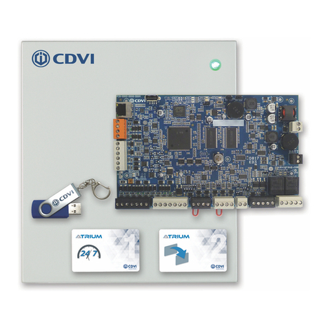
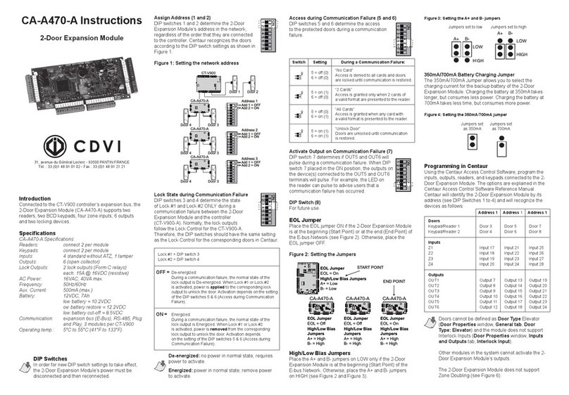
CDVI ATRIUM ADH10 User manual

The Installer’s Choice
cdvigroup.com
ENGLISH
EN
ADH10
ATRIUM
Schlage Integration Module

2cdvigroup.com
EN
ADH10
ATRIUM - Schlage Integration Module (Control up to 10 Schlage Door Handles)
INSTALLATION MANUAL
EN
ADH10
ATRIUM - Schlage Integration Module (Control up to 10 Schlage Door Handles)
INSTALLATION MANUAL
1] PRODUCT PRESENTATION........................................................3
2] NOTES AND RECOMMENDATIONS..................................................4
Free Technical Support ........................................................ 4
Recommended Wiring......................................................... 5
Specications .............................................................. 5
3] PACKAGE CONTENTS ............................................................7
Location and Mounting ........................................................ 8
4] MOUNTING INSTRUCTIONS ......................................................9
Installing the box lock ....................................................... 12
Fixing the Box to its Location .................................................. 13
Installing the ADH10 Controller ................................................. 14
5] WIRING DIAGRAM .............................................................15
Connecting ALLEGION GWE gateway, PIM400-485 or AD-300 ............................ 15
Connecting the Box Tamper Switches ............................................. 16
Power Connections.......................................................... 17
AC Source................................................................ 17
AC Terminal Fuse ........................................................... 18
Battery Backup ............................................................ 19
LED Indicators............................................................. 20
System overview ........................................................... 21
6] WARRANTY - TERMS & CONDITIONS .............................................22
Thank You for buying our products and for
the condence you placed in CDVI.
Copyright (C) 2013 CDVI. All rights reserved. ADH10 is protected by copyright law and international treaties. Unauthorized
reproduction or distribution of this product, or any portion of it, may result in severe civil and criminal penalties, and will be
prosecuted to the maximum extent possible under law.
All other brand and product names are trademarks or registered trademarks of their respective companies.
The information contained in this publication is subject to change without notice.

3
cdvigroup.com
EN
ADH10
ATRIUM - Schlage Integration Module (Control up to 10 Schlage Door Handles)
INSTALLATION MANUAL
EN
ADH10
ATRIUM - Schlage Integration Module (Control up to 10 Schlage Door Handles)
INSTALLATION MANUAL
1] PRODUCT PRESENTATION
One ATRIUM ADH10 controller has the capacity to control ten NDE, AD300 and/or AD400 SCHLAGE door handles.
ATRIUM ver. 3.1 (or higher) multi-account software supports up to 100 door handles per account (site). This
is accomplished by using ten ADH10 controllers connected to an IP network. Eortless auto detect technology
identies the SCHLAGE door handle on the communication bus. A pre-assembled universal power supply is
included with every ADH10 making this unit an industry leader in eciency and simplicity.
• Control10doorhandles
• On-boardEthernetPortwithAES256-bitencryption
• Auto-detecttechnology
• 10,000users
• 10,000cards
• 25,000EventBuer
• 100holidays
• 1,000AccessLevels
• 1,000Scheduleseachsupportingupto
100timeperiods(dd,hh:mm)andrecurrence
• Fullcalendarwithleapyearsupport
• Timezonedenition(fullD.S.T.support)
• 1220m(4000ft)4conductorRS-485expansionbus
(NojumpersorDIPswitches)
• ComprehensiveLEDstatusindicators
SCHLAGEDOORHANDLECOMPATIBILITY:
AD-300
Hardwired Electronic Lock
AD-400
Wireless Electronic Lock
(Work with PIM400-485)
NDE
Wireless Electronic Lock
(Work with GWE)
900MHz
Pre-assembled
universal power supply
included
Low Energy

4cdvigroup.com
EN
ADH10
ATRIUM - Schlage Integration Module (Control up to 10 Schlage Door Handles)
INSTALLATION MANUAL
EN
ADH10
ATRIUM - Schlage Integration Module (Control up to 10 Schlage Door Handles)
INSTALLATION MANUAL
2]NOTESANDRECOMMENDATIONS
FreeTechnicalSupport
For technical support in U.S. or Canada, call 1-866-610-0102, Monday to Friday from 8:00 a.m. to 8:00 p.m.
EST. For international technical support, please see the last page of this document or visit our website: www.
cdvigroup.com.

5
cdvigroup.com
EN
ADH10
ATRIUM - Schlage Integration Module (Control up to 10 Schlage Door Handles)
INSTALLATION MANUAL
EN
ADH10
ATRIUM - Schlage Integration Module (Control up to 10 Schlage Door Handles)
INSTALLATION MANUAL
RecommendedWiring
Specications
Equipment WireType Size Maximum
Length
Ethernet CAT 5/5e - 100m (300ft)
RS485 bus
(Daisy Chain)
Belden 9841, 9842 or equivalent
(2 or 4 conductor shielded) 24AWG (0.51mm) 1220m (4000ft.)
* The Minimum Size Equipment Conductors for the AC mains required are 14 AWG if made of Copper or 12
AWG if made of Aluminium or Copper-Clad Aluminium. Do not use any switch-controlled outlets to power the
system.
SystemResources
Doors 10 doors
Cards and users 10,000 cards and users
Schedules 1000 Schedules each supporting up to 100 time periods
Buered Events 25,000 events
Holidays 100 holidays
Access Levels 1000 access levels
Operating Temperature -20°C to +70°C (-4°F to +158°F)
Humidity 0% to 85% (non-condensing)
System Autonomy Full Distributed Architecture (100% O-line Operation)
Firmware Online Upgradeable
PCB Dimensions 19.9cm (7.83”) x 12.38 cm (4.875”)
Cabinet Dimensions 29 cm (11.4”) high, 28 cm (11”) wide, 8 cm (3.15”) deep
Inputs
Box Tamper Normally Closed (N.C.) contact

6cdvigroup.com
EN
ADH10
ATRIUM - Schlage Integration Module (Control up to 10 Schlage Door Handles)
INSTALLATION MANUAL
EN
ADH10
ATRIUM - Schlage Integration Module (Control up to 10 Schlage Door Handles)
INSTALLATION MANUAL
Communication
LOCAL BUS RS485 @ 9600Baud supporting daisy chain topology, up to 4000ft (1220 meters)
ETHERNET 10/100 Base-T, Auto Sensing, 100m(300ft)
PowerSupply
AC Power 120-240Vac, 1.2A
Frequency 50Hz/60Hz
Output 24Vdc, 2.5A
AC Terminal Fuse 250Vac, 2.5 A, Time Lag, Slow Blow, Operating Temperature: -55oC to +125oC
Power Loss Indicator Yes (DC IN)
Do Not Connect to a Receptacle Controlled by a Switch.
On-BoardProtection(Fuseless,auto-resume)
Battery Against reversal, short, current limited/monitored
Poweroutputspecications
BatteryBackup
Battery Capacity 12Vdc 7Ah rechargeable acid/lead or gel cell backup battery (UL/ULC: YUASA #NP7-12
recommended, Europe: CDVI B7AH recommended). Ensure proper polarity.
Charging Current 250mA (default), 320mA, 500mA, or 1A. Refer to the user interface instruction manual for more
information on how to modify the battery charging current.
Low Battery @ 11.8Vdc
Low Battery Restore @ 12.2Vdc
Low Battery Cut-O @ 10.5Vdc
PowerOutputs(+12Vdc)
LOCAL BUS Maximum Current 1000mA

7
cdvigroup.com
EN
ADH10
ATRIUM - Schlage Integration Module (Control up to 10 Schlage Door Handles)
INSTALLATION MANUAL
EN
ADH10
ATRIUM - Schlage Integration Module (Control up to 10 Schlage Door Handles)
INSTALLATION MANUAL
3] PACKAGE CONTENTS
This chapter details how to install and setup the 10-Door Handle Controller.
What’s in the box:
•OneADH10controller
•metalcabinetandconnectiondiagramlabel
•ACpowercord
•Metalcabinetaccessorykit
•Installationkit
Wall Switch
and a white
wire (115mm)
with a log at
each end
Bolts and Nuts Wall Switch
Spacer
Door Switch
and 2 white
wires (350mm)
with a log at
one end
Door Switch
Support
Metal box
screw
Metal box
lock and key
Metal Cabinet
Accessory Kit 1 2 each 1 1 1 4 1
Pair of Wire,
Red and
black, for
backup battery
(400mm)
Fastener
(PCB Holder)
Installation
Kit 1 pair 5

8cdvigroup.com
EN
ADH10
ATRIUM - Schlage Integration Module (Control up to 10 Schlage Door Handles)
INSTALLATION MANUAL
EN
ADH10
ATRIUM - Schlage Integration Module (Control up to 10 Schlage Door Handles)
INSTALLATION MANUAL
Location and Mounting
Thecabinetisdesignedtobeinstalledindoors,inasafeandsecurelocation.Normaltemperatureandhumidity
levelsshouldbemaintained.
CabinetDimensions:
40cm(15.8”)high,32cm(12.6”)wide,9cm(3.54”)deep
TheCabinetCanAccommodate:
One12Vdc@4.5AHor7AH,gelcelltypebatteryandwiringconnections(15cm(6”)high,
6cm(2.5”)wide,9cm(3.54”)deep)
Battery Model Voltage Capacity Length Width Height
YUASA#NP7-12 12Volt 7 Ah 151mm(5.94”) 65mm(2.56”) 97.5mm(3.84”)
YUASA#NP4-12 12Volt 4.5Ah 90mm(3.54”) 70mm(2.76”) 106mm(4.17”)
MultipleConduitKnock-outs:
Two19.05mm(0.75”)oneachsideandone12.7mm(0.5”)ontop
MinimumClearanceForCabinet:
25cm(10”)clearspacearoundallsides
38cm(15”)clearspaceinfrontofcabinet
MinimumClearanceFromElectricalInterference:
2.4m(8ft.)fromhighvoltageequipmentorwiringandfromelectricalequipmentlikelyto
generate interference
1.2m(4ft.)fromtelephoneequipmentorlinesand8m(25ft.)fromtransmittingequipment
Thesystem’slocationandwiringmethodsshallbeinaccordancewiththeNationalElectricalCode,
ANSI/NFPA70.

9
cdvigroup.com
EN
ADH10
ATRIUM - Schlage Integration Module (Control up to 10 Schlage Door Handles)
INSTALLATION MANUAL
EN
ADH10
ATRIUM - Schlage Integration Module (Control up to 10 Schlage Door Handles)
INSTALLATION MANUAL
4] MOUNTING INSTRUCTIONS
Theboxneedstobepreparedbeforexingittoitslocation.
INSTALLING THE TAMPER SWITCHES
InstallingtamperswitchesallowstheADH10todetectwhenthecabinetdoorisopenedand/orwhenthe
cabinetisremovedfromthewall.Ifneededinstallthetamperswitch(es)asfollows:
Metal box
holes where
toxthewall
tamperswitch

10 cdvigroup.com
EN
ADH10
ATRIUM - Schlage Integration Module (Control up to 10 Schlage Door Handles)
INSTALLATION MANUAL
EN
ADH10
ATRIUM - Schlage Integration Module (Control up to 10 Schlage Door Handles)
INSTALLATION MANUAL
Cabinet Side View
Cabinet Door
Nut
Spacer
Spacer
Screw
Spacer
Installthewalltamperswitchusingthesuppliedboltsandnutsasshowninthefollowingpicture.
Installthetamperswitch
plasticspacerontheback
atbottomleftsideof
the box as show in
the following picture.

11
cdvigroup.com
EN
ADH10
ATRIUM - Schlage Integration Module (Control up to 10 Schlage Door Handles)
INSTALLATION MANUAL
EN
ADH10
ATRIUM - Schlage Integration Module (Control up to 10 Schlage Door Handles)
INSTALLATION MANUAL
Fix the tamper switch to
the bracket then mount
the bracket on the
mounting flange
Door
Tamper Switch
Bracket
Door Tamper Switch
Mounting Flange
Installthedoortamperswitchbyaligningtheswitchholestothepre-installedplasticbracketpins.Pressrmly
tosecurethetamperswitchinposition,thenxthebrackettoismountingange.

12 cdvigroup.com
EN
ADH10
ATRIUM - Schlage Integration Module (Control up to 10 Schlage Door Handles)
INSTALLATION MANUAL
EN
ADH10
ATRIUM - Schlage Integration Module (Control up to 10 Schlage Door Handles)
INSTALLATION MANUAL
Installing the box lock
Installingtheboxlockallowstosecuretheboxfromnon-authorizedaccess.
Ifneededinstalltheboxlockasshown
in the picture (inside view of the door).
1. Removetheboxdoorknock-out.
2. Insertthelockinthehole.
3. Slidethe“U”metalbracketintothelock
groove as shown in the picture to
securethelockinplace.
Alternativelyorcomplementarytotheboxlock,
theboxmaybesecuredbyxingthecoverto
its base using screws.
Howeverthisshouldbedoneonlyoncethe
installation of the full 10-Door Handle Controller
systemiscompleted.
1. Use the 4 screws supplied to secure
the box cover to its base as shown
in the following picture.

13
cdvigroup.com
EN
ADH10
ATRIUM - Schlage Integration Module (Control up to 10 Schlage Door Handles)
INSTALLATION MANUAL
EN
ADH10
ATRIUM - Schlage Integration Module (Control up to 10 Schlage Door Handles)
INSTALLATION MANUAL
Fixing the Box to its Location
Install the box to its location using 4 screws (not supplied) as shown in the following picture.
Ifthewalltamperswitchisused,makesurethatthetamperswitcharmmovesfreelyandis
completelypushedinwhentheenclosureisinstalledonthewall.

14 cdvigroup.com
EN
ADH10
ATRIUM - Schlage Integration Module (Control up to 10 Schlage Door Handles)
INSTALLATION MANUAL
EN
ADH10
ATRIUM - Schlage Integration Module (Control up to 10 Schlage Door Handles)
INSTALLATION MANUAL
Installing the ADH10 Controller
Installthe5suppliedPCBfastenersintheholesidentiedinredintheimagesbelow.
LOCAL
BUS
POWER
SUPPLY
BATT.TAMPER
1
23

15
cdvigroup.com
EN
ADH10
ATRIUM - Schlage Integration Module (Control up to 10 Schlage Door Handles)
INSTALLATION MANUAL
EN
ADH10
ATRIUM - Schlage Integration Module (Control up to 10 Schlage Door Handles)
INSTALLATION MANUAL
5] WIRING DIAGRAM
Connecting ALLEGION GWE gateway, PIM400-485 or AD-300
Connect ALLEGION GWE gateway, PIM400-485 or AD-300 on a 3 conductor RS485 communication loop in daisy
chain or star conguration up to 1220m (4000 ft) from the ATRIUM ADH10 controller.
LOCAL
BUS
POWER
SUPPLY
B AT T.TAMPER
ADH10 LOCAL BUS to
ADH10
Door Handle Controller
GWE
NDE Lock Gateway
or
GND
TDA-
TDB+
AD-300
GND
RDA-
RDB+
PIM400-485
12V
GND
Rx+
Tx
-
You can connect up
to 10 GWE gateways
or PIM400-485 to the
ADH10 RS-485 bus.
The ADH10 can manage
up to 10 door handles
Once the connection is properly done as shown above, the ATRIUM ADH10 will automatically detect
the Allegion GWE gateway, AD-300 or PIM400-485 on power on.
The ADH10 can provide power to up to four GWE Gateways and/or PIM400-485.
Use the supplied GWE transformer to power additional gateways on the same ADH10.

16 cdvigroup.com
EN
ADH10
ATRIUM - Schlage Integration Module (Control up to 10 Schlage Door Handles)
INSTALLATION MANUAL
EN
ADH10
ATRIUM - Schlage Integration Module (Control up to 10 Schlage Door Handles)
INSTALLATION MANUAL
Connecting the Box Tamper Switches
Connecting the tamper switches allows the ADH10 Controller to detect when the cabinet door is opened and/or
when the cabinet is removed from the wall. To install the tamper switches, see “Installing the Tamper Switches”.
To use both switches:
1. Connect one end of the supplied wire to the door tamper switch
terminal and the other end to the wall tamper switch terminal.
2. Connect the other terminal of the door tamper switch to the “TMP” terminals using
the supplied wire.
3. Connect the other terminal of the wall tamper switch to the “GND” terminals using
the supplied wire.
To use only one switch:
1. Connect one terminal of the tamper switch to the “TMP” terminals using the supplied wire.
2. Connect the other terminal of the same tamper switch to the “GND” terminals using
the supplied wire.
If you do not use the tamper switch, connect a wire between the “TMP” and “GND” terminals.
LOCAL
BUS
POWER
SUPPLY
BATT.
TAMPER
Metal Box
Door
Tamper Switch
(N.C.)
Metal Box
Wall
Tamper Switch
(N.C.)

17
cdvigroup.com
EN
ADH10
ATRIUM - Schlage Integration Module (Control up to 10 Schlage Door Handles)
INSTALLATION MANUAL
EN
ADH10
ATRIUM - Schlage Integration Module (Control up to 10 Schlage Door Handles)
INSTALLATION MANUAL
Power Connections
Do not power up the ADH10 Controller until all connections are completed.
The module operates from any 120/240 Vac sources using the supplied AC/DC power supply and provides fully
monitored power solutions using:
• Smart Battery Deep discharge prevention with automatic electronic cut-o.
• Programmable & Adaptive battery charging algorithm (250mA (default), 320mA, 500mA, or 1A).
• Intelligent battery monitoring & charging algorithms allowing optimum performance using standard
lead acid batteries.
• Real Time Monitoring algorithm for ‘Battery Low/Disconnect/Reversal’ and ‘Insucient Main Power’.
AC Source
The AC to DC power supply is pre-installed in the ADH10 Controller box but needs to be connected to the PCB.
1. Connect the AC/DC power
supply output cable to
the ADH10 Controller DC
Power Supply “+” and “-”
terminals. The polarity
of the wires is identied
as shown in the following
picture.
2. Connect the pre-installed
green power LED to the
ADH10 Controller DC Power
Supply “+” and “-” terminals; in parallel with the AC/DC power supply. The red wire goes on the
“+” terminal and the white on the “-” terminal. Make sure that all wires are properly inserted and
tightened.
See “Recommended Wiring” chapter for more information on wiring type, size, and maximum length.
The Minimum Size Equipment Conductors for the AC mains required are 14 AWG if made of Copper or 12
AWG if made of Aluminium or Copper-Clad Aluminium. Do not use any switch-controlled outlets to power
the system. The system is to be connected to a 15A receptacle or circuit.
For PERMANENTLY CONNECTED EQUIPMENT, a readily accessible disconnect device shall be
incorporated external to the equipment.
For PLUGGABLE EQUIPMENT, the socket-outlet shall be installed near the equipment and shall be
easily accessible.
LOCAL
BUS
POWER
SUPPLY
BATT.
TAMPER
1
23
Power Supply
LED Indicator
Power Supply: Input: 120-240Vac, 1.2A,50Hz/60Hz
Output: 24Vdc @ 2.5A
(Do not connect to a receptacle controlled by a switch).
Fuse Rating:
250VAC, 2.5 A
(-55C to +125C)
Red
White
Neutral
Live
Ground

18 cdvigroup.com
EN
ADH10
ATRIUM - Schlage Integration Module (Control up to 10 Schlage Door Handles)
INSTALLATION MANUAL
EN
ADH10
ATRIUM - Schlage Integration Module (Control up to 10 Schlage Door Handles)
INSTALLATION MANUAL
AC Terminal Fuse
The following steps are only presented in case you need to replace the AC terminal fuse.
1. Disconnect the AC power cord from
the power source or for permanent
installation, turn o the power breaker1.
2. Open the AC compartment at
the top left to access the fuse holder.
3. Pull out the fuse holder.
4. Replace the fuse using the same fuse type:
250VAC, 2.5 A
Time Lag, Slow Blow
Operating Temperature: -55oC to +125oC.
Permitted replacements:
a) Littelfuse P/N 021802.5MXP
b) Schurter P/N 0034.3121
c) Various (means any type, from any manufacturer that complies with the “Technical Data and
securement means” and meets the “Mark of conformity” can be used).
5. Replace the fuse holder in its location.
6. Close the AC compartment.
7. Connect the AC power cord to the power source or for permanent installation, turn on the power
breaker1.
1.For permanent installation, this step must be done by a qualied person in accordance with your
local safety regulations.
Fuse holder

19
cdvigroup.com
EN
ADH10
ATRIUM - Schlage Integration Module (Control up to 10 Schlage Door Handles)
INSTALLATION MANUAL
EN
ADH10
ATRIUM - Schlage Integration Module (Control up to 10 Schlage Door Handles)
INSTALLATION MANUAL
Battery Backup
The ADH10 Controller cannot be started on battery power only. Battery backup time varies with each system.
Typical backup time is between 2 and 20 hours using standard equipment and settings.
Wire a 12Vdc (either 4.5Ah or 7Ah) gel type battery and then connect it to the BATT “+” and “-” terminals with
the battery leads supplied.
12Vdc 7Ah rechargeable acid/lead or gel cell backup battery (UL/ULC: YUASA #NP7-12 recommended,
Europe: CDVI B7AH recommended). Ensure proper polarity. Various (means any type, from any
manufacturer that complies with the “Technical Data and securement means” and meets the “Mark of
conformity” can be used).
The battery charge current can be set to either 250mA (default), 320mA, 500mA, or 1A. Refer to the
user interface instruction manual for more information on how to modify the battery charging current.
LOCAL
BUS
POWER
SUPPLY
BATT.TAMPER
1 x Sealed
Rechargeable
GEL Type Battery
12Vdc @ 7Ah

20 cdvigroup.com
EN
ADH10
ATRIUM - Schlage Integration Module (Control up to 10 Schlage Door Handles)
INSTALLATION MANUAL
EN
ADH10
ATRIUM - Schlage Integration Module (Control up to 10 Schlage Door Handles)
INSTALLATION MANUAL
LED Indicators
The ADH10 Controller has several status LEDs that are very useful to diagnose problems when using or
installing the system. Refer to the following image for the location of the LEDs on the PCB. All LEDs are
explained in the following pages.
LOCAL
BUS
POWER
SUPPLY
BATT.TAMPER
1
23
1ETHERNET ACT: Data transmitted/received (Green LED ).
LINK: Ethernet network detected (Green LED ).
2
COM PORT AUX: Green LED, 12 V output power activated.
RX: Green LED ashing, Data received on local bus.
TX: Green LED ashing, Data transmitted on local bus.
3
GLOBAL STAT: - One ash per second: Firmware is operating normally.
- Rapid ash: Firmware is upgrading.
- LED Blink once per 3 second: Card enrollment mode
DC IN: - Green LED: is powered properly.
- Red LED: No primary power.
BATT: - Green LED: Primary power present and battery charging.
- LED O: Primary power present and battery full.
- Red LED: No battery or battery not properly connected.
- Flashing Red LED: Battery power is below 11.8VDC.
Table of contents
Other CDVI Control Unit manuals
Popular Control Unit manuals by other brands

Pentair
Pentair E-Box SOLEO Connect Installation and operation guide

BERGER
BERGER WDP3-01X Safety instructions

Fike
Fike MICROMIST 10-2340 user guide

Ruckus Wireless
Ruckus Wireless ZoneDirector 1200 user guide

Jaycar
Jaycar Maycar Owl Badge Kit manual

Emerson
Emerson Keystone Figure 320 Installation and maintenance instructions