fafnir VISY-Input 8 Guide

FAFNIR GmbH • Schnackenburgallee 149 c • 22525 Hamburg • Germany • Tel.: +49 / 40 / 39 82 07–0 • Fax: +49 / 40 / 390 63 39
Technical Documentation
VISY-Input 8
Digital 8-channel input module
Version: 3
Edition:
2016-09
Art
.no.: 207166

I
Table of contents
1Overview................................................................................................. 1
2Installation .............................................................................................. 1
2.1 Safety information..............................................................................................1
2.2 Requirements.....................................................................................................2
2.3 Installation .........................................................................................................2
2.4 Design and construction.....................................................................................2
2.4.1 Device information .............................................................................................2
2.4.2 Connections.......................................................................................................3
2.4.3 Controls.............................................................................................................3
2.4.4 LEDs...................................................................................................................3
2.5 Connection of the power supply.........................................................................3
2.6 Inputs ................................................................................................................4
2.6.1 Input for external voltage ...................................................................................4
2.6.2 Input for external relay contact ...........................................................................4
2.7 Connection to VISY-Command...........................................................................4
3Configuration ......................................................................................... 5
4Fault diagnosis........................................................................................ 6
4.1 Transmit LED TxD (8) / Receive LED RxD (9) .........................................................6
4.2 Input LEDs (10)...................................................................................................6
4.3 Status LED (11)...................................................................................................6
4.4 12 V LED (12).....................................................................................................7
4.5 Operating voltage LED (13).................................................................................7
5Maintenance ........................................................................................... 7
5.1 Return shipment.................................................................................................7
6Technical data......................................................................................... 8
7List of figures.......................................................................................... 8
8List of tables ........................................................................................... 8
9Appendix................................................................................................. 9
9.1 EU Declaration of Conformity.............................................................................9
Copyright:
Reproduction and translation is only permitted with the written consent of the FAFNIR GmbH. The FAFNIR GmbH
reserves the right to carry out product alterations without prior notice.

Overview Page 1/9
1Overview
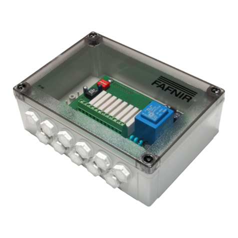
VISY-Input 8 is a digital 8-channel input module, installed in a case with protection class IP66.
It connects external alarm outputs to the VISY-X tank gauging system.
With the VISY-Input 8, external alarm signals can be transmitted to the VISY-Command for
central recording. This allows the indication of alarms at a central location. As VISY-Input 8
has its own housing it can be installed at any position where the simplest wiring can be
made. To connect to the VISY-X tank gauging system only a low-cost communication cable
has to be laid. Up to eight modules VISY-Input 8 can be operated simultaneously with the
VISY-Command.
2Installation
2.1 Safety information
When installing the VISY-Input 8 following safety instructions should be observed:
•The VISY-Input 8 is designed for operation within the VISY-X system only.
•Modifications to the VISY-Input 8 are prohibited without the prior consent of the
manufacturer.
•All installation and maintenance work, with the exception of function testing, must
be carried out with the power disconnected.
•The installation and configuration of the VISY-Input 8 may be carried out only by ex-
pert personnel. Specialised knowledge must be obtained by regular training.
•Operators, installers and service technicians must observe all applicable safety regu-
lations. This also applies to any local safety and accident prevention regulations
which are not stated in this technical documentation.
The safety instructions in this manual are marked as follows:
Failure to observe these safety instructions runs the risk of potential accidents
and damage to the VISY-X system.
Useful tips and information in this manual that should be observed are writ-
ten in italics and identified by this symbol.

Page 2/9 Installation
2.2 Requirements
To connect the VISY-Input 8 to the VISY-X system an interface card of version VI 4 or higher
must be installed and connected to the communication adapter VISY-ICI 485.
2.3 Installation
The VISY-Input 8 is designed for wall mounting inside a building.
For mounting the casing cover must be removed.
2.4 Design and construction
The following figure shows the position of the connectors, LEDs and controls on the board of
the VISY-Input 8.
Figure 1: VISY-Input 8 Design
2.4.1 Device information
(1) Label with the serial number which uniquely identifies the device. When doing the
configuration using VISY-Setup this serial number has to be entered to address the
device.
1
6
3
2
4
5
8
7
9
10
11
12
13
Ser.
no.

Installation Page 3/9
2.4.2 Connections
(2) 24-pin screw terminal for connecting the input signals
(3) 3-pin screw terminal for connecting the power supply
(4) 3-pin screw terminal for connecting the communication
2.4.3 Controls
(5) 2-pin plug connector to activate a terminating impedance for the RS-485 interface.
Normally, the communication on the RS-485 network should be trouble-free with-
out activation of the terminating impedance (jumper not plugged in), because the
data rate is comparatively low.
(6) 2-pin plug connector (one per input) to select the input signal (relay contact or volt-
age input).
For use as a relay contact, the jumper must be plugged in (factory setting).
For use as a voltage input, the jumper must not be plugged in.
(7) 4-way DIL switch, currently without function.
2.4.4 LEDs
(8) Transmit LED TxD (red)
(9) Receive LED RxD (red)
(10) Input LEDs (red) - one per input
(11) Status LED (yellow)
(12) 12 V LED (green) - power for external relay contacts
(13) Operating voltage LED (green)
2.5 Connection of the power supply
The power supply (230 VAC) has to be a permanent installation. The wires for the power
supply are to be connected to the screw terminals marked with PE, N and L.
Figure 2: Power supply screw terminal
PE
N
L

Page 4/9 Installation
2.6 Inputs
VISY-Input 8 has eight input terminals for recording alarms (see below) signalled by external
devices. Each individual input can either act as a digital voltage input or as an input for a re-
lay contact. To connect the input signal one 3-pin screw terminal is used for each input. The
screw terminals are assigned from left to right to the inputs of the top row 2, 4, 6, 8, and the
bottom row 1, 3, 5, 7. The position of the screw terminals is shown in Figure 1.
Figure 3: Input screw terminals
2.6.1 Input for external voltage
If an input shall act as a digital voltage input, the jumper of this input must be removed from
the 2-pin plug connector. The external voltage has to be connected to the terminals "In" and
"GND". This input is then galvanically isolated from the other inputs (removed jumper as-
sumed). Within the permitted voltage range (0 ... 24 V DC) the inputs are protected against
damages caused by reverse polarity.
Switching thresholds:
If UIn ≤1.5 V DC, the input is deactivated, if UIn ≥2.5 V DC, the input is activated.
2.6.2 Input for external relay contact
If an input shall act as input for an external relay contact, the jumper of this input must be
plugged onto the 2-pin plug connector (factory setting). The external relay contact has to be
connected to the terminals "In" and "+12 V" of the input.
For the supply of external relay contacts VISY-Input 8 has an internal 12 V voltage supply.
The inputs are galvanically connected by the internal 12 V voltage supply. The maximum cur-
rent via the relay contact is limited to 10 mA ±10 %.
2.7 Connection to VISY-Command
Up to eight modules VISY-Input 8 can be operated simultaneously with the VISY-X tank
gauging.
For the connection of VISY-Input 8 a communication adapter VISY-ICI 485 is required which
must be installed inside VISY-Command. The communication between VISY-ICI 485 and
VISY-Input 8 is performed via a galvanically isolated RS485 interface. The communication line
is to be connected to the terminals A, B and GND of the 3-pin screw terminal.
GND In +12V GND In +12V GND In +12V GND In +12V
Input 2 Input 4 Input 6 Input 8
Input 1 Input 3 Input 5 Input 7

Configuration Page 5/9
For the wiring of VISY-Input 8 with VISY-ICI 485 it is recommended using a 3-core cable with
signal ground (GND connection terminal) to increase the noise immunity.
Figure 4: Communication screw terminal
Additional information about the connection of the communication line can be found in the
documentation of VISY-ICI 485, see:
•Technical Documentation VISY-ICI 485, art. no. 207150
3Configuration
For VISY-Input 8 the function of each input must be set by inserting or removing the corre-
sponding jumper (see section 2.6).
Further configuration of VISY-Input 8 is done - as usual for the VISY-X system - with the con-
figuration software VISY-Setup.
Wired version of the VISY-X system:
If VISY-Input 8 is used with the wired version of the VISY-X system, the data
protocol for communication with the VISY-Stick must be set to “Multi Probe”
using the VISY-Setup. Due to the shorter communication times, “Multi Probe
4800 bps” should preferably be used.
Wireless version of the VISY-X system:
If VISY-Input 8 is used with the wireless version of the VISY-X system, the data
protocol for communication with the VISY-Stick must be set to “Standard VISY
TLG“.
Please follow the appropriate instructions in the VISY-Setup manual.
•Technical Documentation VISY-Setup V4, art. no. 207158
After the configuration it should be tested whether the alarm signalling
works as expected.
GND
A
B

Page 6/9 Fault diagnosis
4Fault diagnosis
VISY-Input 8 has several LEDs which help in diagnosing problems. The positions of the LEDs
can be found in the figure 1.
4.1 Transmit LED TxD (8) / Receive LED RxD (9)
The two red communication LEDs indicate, whether data are received or transmitted from
VISY-Input 8.
Under normal conditions, the communication LEDs should light up regularly.
4.2 Input LEDs (10)
The eight red input LEDs indicate, whether an input is activated or deactivated.
The LEDs are assigned from left to right to the inputs 1 to 8.
If an input is used as voltage input, the related input LED is on, when the
voltage at the clamps"In" and "GND" is in the range of +5 V to +24 V.
If an input is used as relay input, the related input LED is on, when the relay
contact connected to the terminals "In" and "+12 V" is closed.
4.3 Status LED (11)
The yellow status LED indicates the status of the communication between interface card VI in
the VISY-Command and VISY-Input 8. The following table lists the possible states of the sta-
tus LED and explains their meanings.
Status LED
Error
Description
on
no error
correct data are regularly received
continuously
blinking
no communication
no data were received since the last power up
1 x short
flashing
interruption of the
communication
no correct data were received for more than 1 minute
Table 1: Status LED
Under normal conditions, the status LED should remain illuminated.

Maintenance Page 7/9
4.4 12 V LED (12)
The green 12 V LED indicates whether the 12 V is available for powering the external relay
contacts. After switching on the power supply, the 12 V LED illuminates continuously. A
flickering or extinguished LED indicates a problem with the power supply or the AC adapter.
4.5 Operating voltage LED (13)
The green operating voltage LED indicates whether VISY-Input 8 is supplied with voltage.
After switching on the power supply, the operating voltage LED illuminates continuously. If
the LED flickers or is unlit, this indicates a problem with the power supply or the mains
adapter.
5Maintenance
5.1 Return shipment
Before returning any FAFNIR equipment the returned goods authorization by the FAFNIR
customer care is required. Please contact your account manager or the customer care to get
the instructions for the return of goods.
The return of FAFNIR equipment is possible only with authorization by the
FAFNIR customer care.

Page 8/9 Technical data
6Technical data
Dimensions: H 60 x W 180 x D 130 [mm] (without cable glands)
Casing protection class: IP66
Ambient temperature: 0 °C ... +40 °C
Power supply: 230 VAC ±10 %, 50 - 60 Hz, ≤4 VA
Communication: 1 x RS-485, galvanically isolated, 3-pin. screw terminal with
ground (GND) to connect to VISY-ICI 485
Inputs: 8 inputs, configurable either as digital voltage inputs or as
inputs for relay contacts
voltage input: 5 V DC (app. 1 mA) ... 24 V DC (app. 7 mA),
galvanically isolated and protected against reverse polarity
Input for relay contact internal power supply, 12 V DC, current through the relay con-
tact is limited to 10 mA ± 10%
Table 2: Technical data
7List of figures
Figure 1: VISY-Input 8 Design......................................................................................... 2
Figure 2: Power supply screw terminal............................................................................ 3
Figure 3: Input screw terminals....................................................................................... 4
Figure 4: Communication screw terminal........................................................................ 5
8List of tables
Table 1: Status LED ........................................................................................................ 6
Table 2: Technical data................................................................................................... 8


FAFNIR GmbH
Schnackenburgallee 149 c
22525 Hamburg
Germany
Tel.: +49 / 40 / 39 82 07–0
Fax: +49 / 40 / 390 63 39
E-mail: info@fafnir.de
Web: www.fafnir.com
Table of contents
Other fafnir Control Unit manuals
Popular Control Unit manuals by other brands

Numato Lab
Numato Lab Galatea IP4776CZ38 user guide

Lenze
Lenze E94AYCDN Mounting instructions

Novax
Novax IntelliCross TouchFree Kit installation guide

rtd
rtd cpuModules CMA34CR user manual

Dewetron
Dewetron DAQP-MULTI Technical reference manual

Siemens
Siemens SIMOCODE pro 3UF7400-1AA00-0 operating instructions