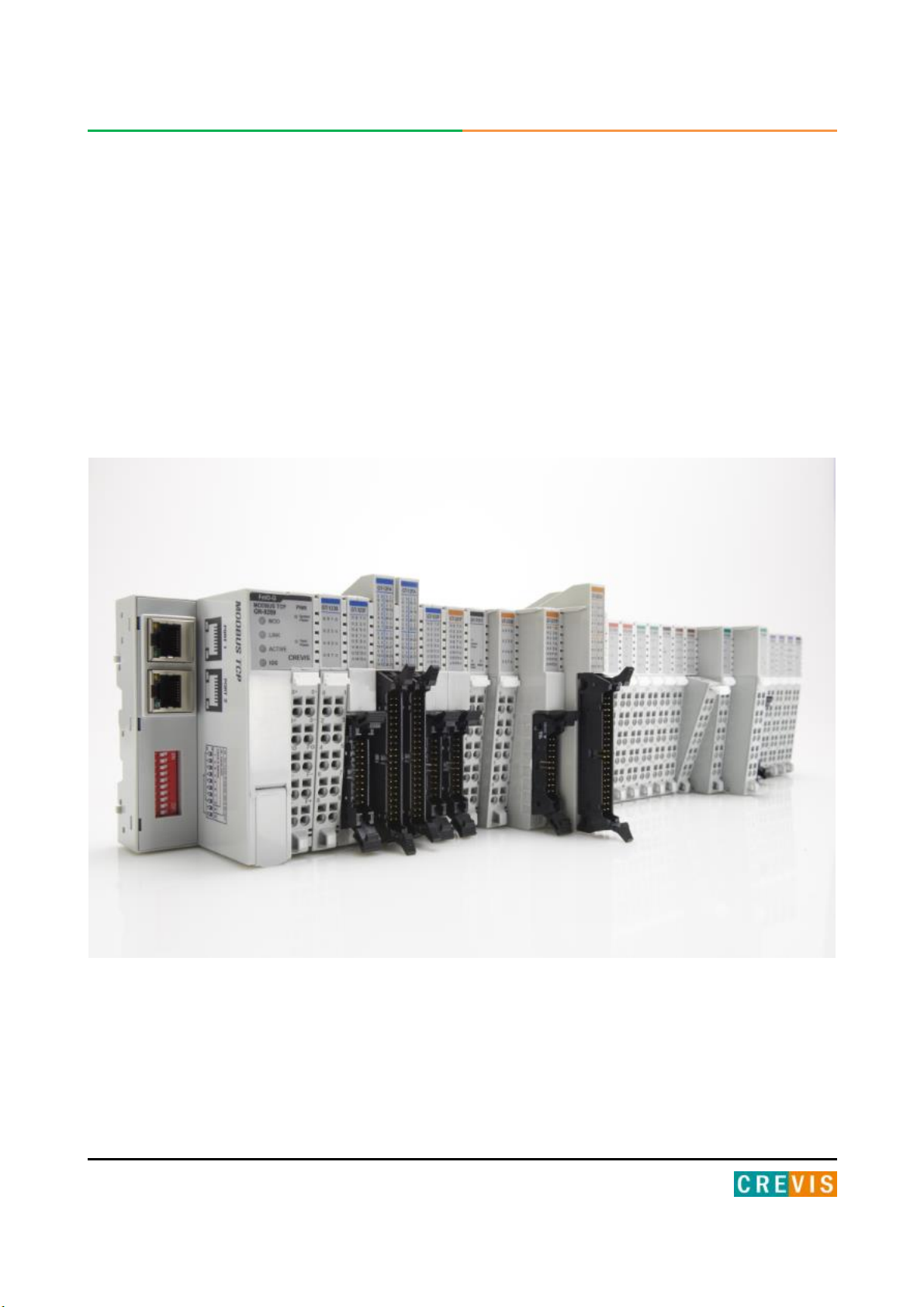
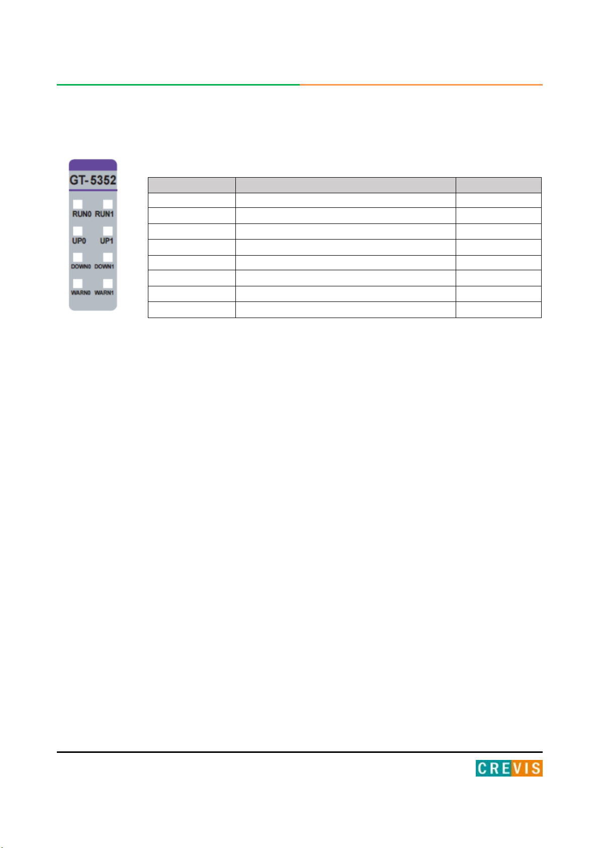
CREVIS GT-5352 User manual

1FnIO G-Series
Copyright(C)CREVIS Co.,Ltd Support +82-31-899-4599 URL: www.crevis.co.kr
Version 1.0
GT-5352
Special IO Module
User Manual

2FnIO G-Series
Copyright(C)CREVIS Co.,Ltd Support +82-31-899-4599 URL: www.crevis.co.kr
DOCUMENT CHANGE SUMMARY
REV
PAGE
REMARKS
DATE
EDITOR
1.0
New Document
2018/07/30
CH HONG
2018 CREVIS Co.,Ltd

3FnIO G-Series
Copyright(C)CREVIS Co.,Ltd Support +82-31-899-4599 URL: www.crevis.co.kr
Table of Contents
1. Important Notes.......................................................................................................................... 4
1.1. Safety Instruction................................................................................................................. 5
1.1.1. Symbols..............................................................................................................................5
1.1.2. Safety Notes....................................................................................................................... 5
1.1.3. Certification.........................................................................................................................5
2. Specification................................................................................................................................6
2.1. GT-5352............................................................................................................................... 6
2.1.1. Wiring Diagram............................................................................................................... 6
2.1.2. LED Indicator.................................................................................................................. 7
2.1.3. Specification....................................................................................................................8
2.1.4. Mapping data into the image table..................................................................................9
2.1.5. ConfigurationParameter Data..................................................................................... 10
3. EnvironmentSpecification.........................................................................................................11
4. Dimension................................................................................................................................. 12
5. Mounting................................................................................................................................... 13
5.1 I/O Inserting and Removing Devices................................................................................... 13
5.2 RTB (Removable Terminal Block)........................................................................................14
6. G-Bus Pin Description...............................................................................................................15

4FnIO G-Series
Copyright(C)CREVIS Co.,Ltd Support +82-31-899-4599 URL: www.crevis.co.kr
1. Important Notes
Solid state equipment has operational characteristics differing from those of electromechanical equipment.
Safety Guidelines for the Application, Installation and Maintenance of Solid State Controls describes some
important differences between solid state equipment and hard-wired electromechanical devices.
Because of this difference, and also because of the wide variety of uses for solid state equipment, all
persons responsible for applying this equipment must satisfy themselves that each intended application of
this equipment is acceptable.
In no event will CREVIS be responsible or liable for indirect or consequential damages resulting from the use
or application of this equipment.
The examples and diagrams in this manual are included solely for illustrative purposes. Because of the
many variables and requirements associated with any particular installation, CREVIS cannot assume
responsibility or liability for actual use based on the examples and diagrams.
If you don't follow the directions, it could cause a personal injury, damage to the equipment or
explosion
Do not assemble the products and wire with power applied to the system. Else it may cause an electric
arc, which can result into unexpected and potentially dangerous action by field devices. Arching is
explosion risk in hazardous locations. Be sure that the area is non-hazardous or remove system power
appropriately before assembling or wiring the modules.
Do not touch any terminal blocks or IO modules when system is running. Else it may cause the unit to
an electric shock or malfunction.
Keep away from the strange metallic materials not related to the unit and wiring works should be
controlled by the electric expert engineer. Else it may cause the unit to a fire, electric shock or
malfunction
If you disobey the instructions, there may be possibility of personal injury, damage to equipment
or explosion. Please follow below Instructions.
•Check the rated voltage and terminal array before wiring. Avoid the circumstances over 50℃of
temperature. Avoid placing it directly in the sunlight.
•Avoid the place under circumstances over 85% of humidity.
•Do not place Modules near by the inflammable material. Else it may cause a fire.
•Do not permit any vibration approaching it directly.
•Go through module specification carefully, ensure inputs, output connections are made with the
specifications. Use standard cables for wiring.
•Use Product under pollution degree 2 environment.
Warning!
Caution!

5FnIO G-Series
Copyright(C)CREVIS Co.,Ltd Support +82-31-899-4599 URL: www.crevis.co.kr
1.1. Safety Instruction
1.1.1. Symbols
1.1.2. Safety Notes
The modules are equipped with electronic components that may be destroyed by
electrostatic discharge. When handling the modules, ensure that the environment (persons,
workplace and packing) is well grounded. Avoid touching conductive components, RBUS
Pin.
1.1.3. Certification
c-UL-us UL Listed Industrial Control Equipment, certified for U.S. and Canada
See UL File E235505
CE Certificate
EN 61000-6-2; Industrial Immunity
EN 61000-6-4; Industrial Emissions
Reach, RoHS (EU, CHINA)
Identifies information about practices or circumstances that can cause an
explosion in a hazardous environment, which may lead to personal injury or
death property damage, or economic loss
Identifies information that is critical for successful application and understanding of the
product
Identifies information about practices or circumstances that can lead to personal
injury, property damage, or economic loss.
Attentions help you to identity a hazard, avoid a hazard, and recognize the
consequences

6FnIO G-Series
Copyright(C)CREVIS Co.,Ltd Support +82-31-899-4599 URL: www.crevis.co.kr
2. Specification
2.1. GT-5352
2.1.1.Wiring Diagram
Pin No.
Signal Description
Signal Description
Pin No.
0
Pulse Output + Ch# 0
Pulse Output - Ch# 0
1
2
Input Data + Ch# 0
Intput Data - Ch# 0
3
4
Pulse Output + Ch# 1
Pulse Output - Ch# 1
5
6
Input Data + Ch# 1
Intput Data - Ch# 1
7
8
Field Ground
Field Ground
9

7FnIO G-Series
Copyright(C)CREVIS Co.,Ltd Support +82-31-899-4599 URL: www.crevis.co.kr
2.1.2. LED Indicator
LED No.
LED Function / Description
LED Color
RUN0
Run state Ch#0
Green
RUN1
Run state Ch#1
Green
UP0
Encoder is rotating counter clockwise. Ch#0
Green
UP1
Encoder is rotating counter clockwise. Ch#1
Green
DOWN0
Encoder is rotating clockwise. Ch#0
Green
DOWN1
Encoder is rotating clockwise. Ch#1
Green
WARN0
Warning state (WFP, WSSIF, WSSID) Ch#0
Green
WARN1
Warning state (WFP, WSSIF, WSSID) Ch#1
Green

8FnIO G-Series
Copyright(C)CREVIS Co.,Ltd Support +82-31-899-4599 URL: www.crevis.co.kr
2.1.3. Specification
Items
Specification
Input Specification
Number of Channel
2 Channel - Synchronous Serial Interface Module
Indicators
8 Green LEDs
RUN0, RUN1, UP0, UP1, DOWN0, DOWN1, WARN0, WARN1
SSI Data Rate
Channel 0, 1 – 125K, 250K, 500K, 1M, 2M(default 250K)
SSI Data Width
Max. 30bit
SSI Data Delay Time
100usec ~ 10msec(default 200us)
SSI Output
C+, C- : Ch0,1 RS422 Differential Output
SSI Input
D+, D- : Ch0,1 RS422 Differential Input
SSI Data Code Type
Gray Code or Natural Binary
Receiver Common Mode Input Voltage
(Data Input Voltage)
-7~7Vdc
Output Voltage
(Clock Output Voltage)
-0.5~4.3Vdc
Special features
Adjustable baud rate, delay and data length
General specification
Power Dissipation
60mA maximum @ 5.0Vdc
Isolation
I/O to Logic : Photo coupler isolation
I/O to Field Power : Non-Isolation
Field Power
Supply voltage : 24Vdc nominal
Voltage range :
70℃18~26.4Vdc
60℃18~32Vdc
Power Dissipation : Max. 30mA @ 24Vdc
Wiring
I/O Cable Max. 2.0mm2(AWG 14)
Weight
60g
Module Size
12mm x 90.5mm x 65mm
Environment Condition
Refer to ‘1. Environment Specification’

9FnIO G-Series
Copyright(C)CREVIS Co.,Ltd Support +82-31-899-4599 URL: www.crevis.co.kr
2.1.4. Mapping data into the image table
•Input Image Data – 10Byte
Byte
Bit 7
Bit 6
Bit 5
Bit 4
Bit 3
Bit 2
Bit 1
Bit 0
0
SSI Data LL Ch#0
1
SSI Data LH Ch#0
2
SSI Data HL Ch#0
3
SSI Data HH Ch#0
4
SSI Data LL Ch#1
5
SSI Data LH Ch#1
6
SSI Data HL Ch#1
7
SSI Data HH Ch#1
8
RUN Ch#0
WARN
Ch#0
DEC Ch#0
INC Ch#0
_
_
WFP Ch#0
WSSIF
Ch#0
WSSID
Ch#0
9
RUN Ch#1
WARN
Ch#1
DEC Ch#1
INC Ch#1
_
_
WFP Ch#1
WSSIF
Ch#1
WSSID
Ch#1
- SSI Data word is a 32bit-wide data. Ch#0,1
- RUN : SSI Clock Output Enabled Flag
- WARN : Warning. Any warning has occurred, WFP, WSSIF or WSSID.
- DEC : SSI Data Decrement. It was set, it lasts until INC.
- INC : SSI Data Increment. It was set, it lasts DEC.
- WFP : Warning of Field Power (SSI Power).
- WSSIF : Warning of SSI Frame. The last bit of frame data is not trailed with 0.
- WSSID : Warning of SSI Data. SSI Data is 0 during gap of frames. Generally when invalid wiring or cross
wiring.
•Output Image Data – 4Byte
Byte
Bit 7
Bit 6
Bit 5
Bit 4
Bit 3
Bit 2
Bit 1
Bit 0
0
RUN Ch#0
GRAY Ch#0
--
SSI Data Length (0~30) Ch#0
1
SSI Data Delay Time Selection Ch#0
SSI Data Rate Selection Ch#0
2
RUN Ch#1
GRAY Ch#1
--
SSI Data Length (0~30) Ch#1
3
SSI Data Delay Time Selection Ch#1
SSI Data Rate Selection Ch#1
- RUN : SSI Clock Output Command, 1:Run, 0:Stop
- GRAY : Conversion Binary to Gray code. 1:Gray, 0:Binary (It has effect on Current SSI Data.)
- SSI Data Length : Sensor Resolution Bit + Sensor Number of turn Bit.
Example) Sensor Resolution (Step/Revolution)=8192 => 13bit, Sensor Number of turn=4092 => 12bit
SSI Data Length must be 25 (13bit + 12bit).

10 FnIO G-Series
Copyright(C)CREVIS Co.,Ltd Support +82-31-899-4599 URL: www.crevis.co.kr
SSI Data Rate Selection
Value
Description
Ch#0
Ch#1
0(B`0000)
250Kbps (Default)
1(B`0001)
125Kbps
2(B`0010)
250Kbps
3(B`0011)
500Kbps
4(B`0100)
1Mbps
5(B`0101)
2Mbps
SSI Data Delay Time Selecton
Value
Description
Value
Description
0(B`0000)
200usec (Default)
8(B`1000)
800usec
1(B`0001)
100usec
9(B`1001)
900usec
2(B`0010)
200usec
10(B`1010)
1msec
3(B`0011)
300usec
11(B`1011)
2msec
4(B`0100)
400usec
12(B`1100)
3msec
5(B`0101)
500usec
13(B`1101)
4msec
6(B`0110)
600usec
14(B`1110)
5msec
7(B`0111)
700usec
15(B`1111)
10msec
2.1.5. Configuration Parameter Data – 8byte
Byte
Bit 7
Bit 6
Bit 5
Bit 4
Bit 3
Bit 2
Bit 1
Bit 0
0
Reserved
1
Reserved
2
Reserved
3
Reserved
4
Reserved
5
Reserved
6
Reserved
7
Reserved

11 FnIO G-Series
Copyright(C)CREVIS Co.,Ltd Support +82-31-899-4599 URL: www.crevis.co.kr
3. Environment Specification
Environmental specification
Operating Temperature
-40℃~70℃
UL Temperature
-20℃~60℃
Storage Temperature
-40℃~85℃
Relative Humidity
5% ~ 90% non-condensing
Mounting
DIN rail
General specification
Shock Operating
IEC 60068-2-27
Vibration Resistance
Sine Vibration
- 5 ~ 25Hz : ±1.6mm
- 25 ~ 300Hz : 4g
- Sweep Rate : 1 Oct/min, 20 Sweeps
Random Vibration
- 10 ~ 40 Hz : 0.0125 g2/Hz
- 40 ~ 100 Hz : 0.0125 → 0.002 g2/Hz
- 100 ~ 500 Hz : 0.002 g2/Hz
- 500 ~ 2000 Hz : 0.002 → 1.3 x 10⁻⁴g2/Hz
- Test time : 1hrs for each test
EMC Resistance
EN61000-6-2 : 2005
EN 61000-6-4 : 2007+A1:2011
Installation Pos. / Protect. Class
Variable/IP20
Product Certifications
CE, UL

12 FnIO G-Series
Copyright(C)CREVIS Co.,Ltd Support +82-31-899-4599 URL: www.crevis.co.kr
4. Dimension

13 FnIO G-Series
Copyright(C)CREVIS Co.,Ltd Support +82-31-899-4599 URL: www.crevis.co.kr
5. Mounting
•Hot surface!
The surface of the housing can become hot during operation. If the device was operated at high ambient
temperatures, allow it to cool off before touching it.
•Perform work on devices only if they are de-energized!
Working on energized devices can damage them. Therefore, turn off the power supply before working
on the devices.
5.1 I/O Inserting and Removing Devices
- As above figure in order to safeguard the FnIO module from jamming, it should be fixed onto the DIN rail
with locking level. To do so, fold on the upper of the locking lever.
To pull out the FnIO module, unfold the locking lever as below figure.
Caution!
Notice!

14 FnIO G-Series
Copyright(C)CREVIS Co.,Ltd Support +82-31-899-4599 URL: www.crevis.co.kr
5.2 RTB (Removable Terminal Block)
•Whole terminal block can be combined and removed for the convenience if its maintenance.
•There is a locking switch on the RTB for the easy combination and easy removal.
•Easy combination and easy removal for IO modules on the din rail through One Touch Locking
Switch.

15 FnIO G-Series
Copyright(C)CREVIS Co.,Ltd Support +82-31-899-4599 URL: www.crevis.co.kr
6. G-Bus Pin Description
Communication between the RN series and the expansion module as well as system / field power supply of
the bus modules is carried out via the internal bus. It is comprised of 6 data pin and 2 field power pin.
Do not touch data and field power pins in order to avoid soiling and damage by
ESD noise.
*Please refer to the table below regarding the pin description from P1 to P8.
No.
Description
P1
Field Power (VCC)
P2
Field Power (GND)
P3
GBUS CLK
P4
GBUS MISO
P5
GBUS MOSI
P6
GBUS Token
P7
System Power (GND)
P8
System Power (VCC)
Table of contents
Other CREVIS Control Unit manuals
Popular Control Unit manuals by other brands

Harvia
Harvia XENIO COMBI CX30C-U1 Instructions for installation and use

Azbil
Azbil ACTIVAL VY5303A Specifications & instructions

CMO VALVES
CMO VALVES UB Series Instruction and maintenance manual

HWH
HWH 725 SERIES Operator's manual

EOS
EOS Infratec Classic Assembly and operating instruction

IDS
IDS hyyp AppConnectLTE Plugon quick start guide

jcm-tech
jcm-tech RB3 TGLA868 user manual

Espressif
Espressif ESP32--MINI--1 user manual

Siemens
Siemens SIRIUS Star-Delta Combination S2 Original operating instructions

Acromag
Acromag AcroPack AP513 user manual

Hartmann
Hartmann T2HCK5 installation guide

Siemens
Siemens SIRIUS ACT 3SU14 Original operating instructions