CrimeStopper VSMC-1000 User manual

CONGRATULATIONS on your choice of a CrimeStopper Multi Channel Video Switcher. This booklet contains all of
the necessary information for using, and maintaining your video switcher. If any questions should arise, contact
your installation facility or check out the Knowledge Base at www.crimestopper.com
VSMC-1000
VIDEO SWITCHER
MULTI-
CHANNEL
VIDEO
SWITCHER
INSTALLATION MANUAL1230-60033-01-B

2
INTRODUCTION
This multi-channel video switcher will allow you to install multiple cameras (not included) into a vehicle and have them
triggered simply by turning your turn signals on or by placing your vehicle in reverse. This product is intended to be used in
addition to using the vehicles mirrors and is no way meant to replace them.
TABLE OF CONTENTS
Introduction 2
System Overview 3
Wiring 4-5
Specications 6
French 7-9
Spanish 10-12
Warranty 13

3
SYSTEM OVERVIEW
LEFT RIGHT FRONT REAR VID OUT POWER
(+) Accessory Input - RED
(+) Left Camera Trigger - WHITE
(+) Right Camera Trigger - GREY
(+) Front Camera Trigger - GREEN
(+) Rear Camera Trigger - PURPLE
(-) Ground - BLACK
2 A/32 V
84”
84”
84”
18”
84”

4
WIRING
(+) Accessory Input - RED
(+) Left Camera Trigger - WHITE
(+) Right Camera Trigger - GREY
(+) Front Camera Trigger - GREEN
(+) Rear Camera Trigger - PURPLE
(-) Ground - BLACK
2 A/32 V
Red - 12V Out
Black - Video (-)
12V Ground
Yellow - Video (+)
Red - 12V Out for Camera
Black - 12V Ground for Camera

5
WIRING
Red – Accessory (+) In – This will be connected to the vehicle’s Accessory wire. This wire powers the video switcher and will give
power to the all connected video cameras.
White – Left Camera Input Trigger – This wire should be connected to the vehicle’s positive left turn signal wire. This will trigger the
camera on the LEFT side of the vehicle to turn ON and output video to the display. The input will stay active long enough that the pulse
from the turn signal will keep the camera on until the turn signal is shut off.
Grey – Right Camera Input Trigger – This wire should be connected to the vehicle’s positive right turn signal wire. This will trigger
the camera on the RIGHT side of the vehicle to turn ON and output video to the display. The input will stay active long enough that the
pulse from the turn signal will keep the camera on until the turn signal is shut off.
Green – Front Camera Input Trigger – This wire should be connected to the vehicle’s 12-volt positive accessory wire. This will output
video at all times unless another camera input is triggered. If you do not want the front camera ON at all times simply connect it through
a switch to allow you to turn it ON or OFF manually.
Purple – Rear Camera Input Trigger – This wire should be connected to the vehicle’s positive reverse / back up light signal wire. This
will trigger the camera on the REAR of the vehicle to turn ON and output video to the display.
Black – Ground – This wire needs to be grounded to a clean, paint free metal surface of the vehicle. The best installation practices
recommend grounding in the kick panel area of the vehicle.

6
SPECIFICATIONS
Input Voltage (Min/Max) Min 9V / Max 16V
Camera Output Voltage 1Vp-p @ 75ohms
Output Resolution Pass-through
Fused Rating 2 Amp
Temperature (Min/Max) -20°C (-4°F)/ 85°C (185°F)
Amperage Output (Min/Max) 89.2mA Min/ 355.3mA Max
Dimensions (LxWxH) 4-1/8” X 2-5/16” X 13/16”
(103mm X 58mm x 20mm)

7
INTRODUCTION
Rouge – Entrée accessoire (+) – Ceci sera connecté au l d'accessoire du véhicule. Ce l alimente le mélangeur vidéo et alimentra
toutes les caméras vidéo connectées.
Blanc – Déclencheur d'entrée de caméra gauche – Ce l doit être connecté au l de clignotant gauche positif du véhicule. Ceci
déclenchera l'activation de la caméra sur le côté GAUCHE du véhicule et la vidéo de sortie sur l'afchage. L'entrée restera active
sufsamment longtemps pour que l'impulsion du clignotant garde la caméra activée jusqu'à désactivation du clignotant.
Gris – Déclencheur d'entrée de caméra droit – Ce l doit être connecté au l de clignotant droit positif du véhicule. Ceci déclenchera
l'activation de la caméra sur le côté DROIT du véhicule et la vidéo de sortie sur l'afchage. L'entrée restera active sufsamment
longtemps pour que l'impulsion du clignotant garde la caméra activée jusqu'à désactivation du clignotant.
Vert – Déclencheur d'entrée de caméra avant – Ce l doit être connecté au l d'accessoire positif de 12 volts du véhicule. Ceci
produira une vidéo à tout moment sauf si une entrée d'une autre caméra est déclenchée. Si on ne souhaite pas que la caméra avant soit
en marche à tout moment, il suft de la connecter via un commutateur pour pouvoir la mettre en marche et l'éteindre manuellement.
Violet – Déclencheur d'entrée de caméra arrière – Ce l doit être connecté au l de feu arrière positif du véhicule. Ceci déclenchera
l'activation de la caméra sur l'ARRIÈRE du véhicule et la vidéo de sortie sur l'afchage.
Noir – Terre – Ce l doit être mis à la terre sur une surface métallique propre et exempte de peinture du véhicule. Les meilleures
pratiques d'installation recommandent une mise à la terre dans la zone de pied de caisse du véhicule.
CABLAGE
Ce mélangeur vidéo multicanaux vous permettra d'installer plusieurs caméras (non fournies) dans un véhicule et de les déclencher
simplement en activant vos clignotants ou en mettant votre véhicule en marche arrière. Ce produit est conçu pour être utilisé en plus
de l'utilisation des rétroviseurs et n'est en aucun cas prévu pour les remplacer.

8
SPÉCIFICATIONS
Tension d'entrée (Mini/Maxi) Mini 9 V / Maxi 16 V
Tension de sortie de caméra 1 Vp-p @ 75 ohms
Résolution de sortie Transmission
Calibre du fusible 2 A
Température (Mini/Maxi) -20 °C (-4 °F)/ 85 °C (185 °F)
Sortie d'ampérage (Mini/Maxi) 89,2 mA Mini/ 355,3 mA Maxi
Dimensions (L x l x h) 4-1/8” X 2-5/16” X 13/16”
(103 mm x 58 mm x 20 mm)

9
INTRODUCCIÓN
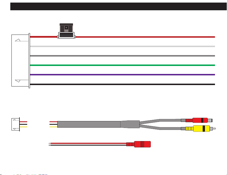
Rojo – Entrada para accesorios (+) – Esto se conectará al cable para accesorios del vehículo. Este cable alimenta el conmutador de
vídeo y da alimentación a todas las cámaras de vídeo conectadas.
Blanco – Disparador de entrada de la cámara izquierda – Se debe conectar este cable al cable positivo de la señal de giro a la
izquierda del vehículo. Esto disparará la cámara del lado IZQUIERDO del vehículo para encender (ON) la misma y emitir la señal de vídeo
a la pantalla. La entrada seguirá activa tiempo suciente para que el pulso de la señal de giro mantenga la cámara encendida hasta
que se apague la señal de giro.
Gris – Disparador de entrada de la cámara derecha – Se debe conectar este cable al cable de señal positivo de giro a la derecha del
vehículo. Esto disparará la cámara del lado DERECHO del vehículo para encender (ON) la misma y emitir la señal de vídeo a la pantalla.
La entrada seguirá activa tiempo suciente para que el pulso de la señal de giro mantenga la cámara encendida hasta que se apague
la señal de giro.
Verde– Disparador de entrada de la cámara delantera – Se debe conectar este cable al cable de accesorios de 12 voltios positivos.
Esto emitirá una señal de video en todo momento a menos que se accione otra cámara. Si no quiere la cámara delantera encendida (ON)
en todo momento, simplemente conéctela a través de un interruptor para poder encender y apagar la cámara manualmente.
Púrpura – Disparador de entrada de la cámara trasera – Se debe conectar este cable al cable de señal positivo de la luz de marcha
atrás / retroceso del vehículo. Esto disparará la cámara del lado TRASERO del vehículo para encender (ON) la misma y emitir la señal
de vídeo a la pantalla.
Negro – A tierra – Se debe conectar a tierra este cable a una supercie limpia de metal, sin pintura del vehículo. Las mejores prácticas
de instalación recomiendan conectar a tierra en el área del panel de placa de defensa.
CABLEADO
Este conmutador de vídeo de múltiples canales le permitirá instalar múltiples cámaras (cámara no incluido) en un vehículo y hacer
que se activen simplemente accionando las señales de giro o colocando el vehículo en marcha atrás. Este producto es para ser usado
además de usar los espejos del automóvil y no es de manera alguna un reemplazo de los mismos.

10
Voltaje de entrada (Mín./Máx.) Mín. 9V / Máx. 16V
Voltaje de salida de la cámara 1Vp-p @ 75 ohmios
Resolución de la salida Transferencia
Calicación con fusible 2 Amperios
Temperatura (Mín,/Máx.) -20°C (-4°F)/ 85°C (185°F)
Amperaje de salida (Mín./Máx.) 89.2mA Mín./ 355.3mA Máx.
Dimensiones (LxAxA) 4-1/8 X 2-5/16 X 13/16 pulg.
(103mm x 58mm x 20mm)
ESPECIFICACIONES

11

12
LIMITED WARRANTY
Rockford Corporation offers a limited warranty on all CrimeStopper products as detailed below and on the following terms:
ALL SAFETY PRODUCTS
Length Of Warranty - 1 Year
SECURITY and REMOTE START PRODUCTS
Length Of Warranty
Limited Lifetime, CrimeStopper will repair or replace defective modules with a comparable new or refurbished module during reasonable usage and the lifetime of the vehicle
in which it is originally installed provided that the module is returned to Rockford, shipping pre-paid and accompanied by a legible copy of the original sales receipt from the
authorized dealer containing; the consumer’s name, authorized dealer’s name, date of purchase, item or sku number, product description, and the year make and model of the
vehicle in which it is installed. The additional componentry of the system, including but not limited to remotes, antennas and harnesses, are covered by a one year warranty from
the date of original purchase. Products received for repair or replacement without proof of purchase from an authorized dealer will be denied.
What Is Covered
This warranty applies only to CrimeStopper products sold to consumers by authorized CrimeStopper dealers in the United States of America Products purchased by consumers
from an Authorized CrimeStopper Dealer in any other country are covered only by that country’s Distributor and not by Rockford Corporation.
Who Is Covered
This warranty covers only the original purchaser of CrimeStopper product purchased from an authorized CrimeStopper dealer. In order to receive service, the purchaser must
provide Rockford Corporation with a copy of the original sales receipt stating the customer name, dealer name, product purchased and date of purchase. Products found to be
defective during the warranty period will be repaired or replaced with a product deemed to be equivalent at Rockford’s sole discretion.
What Is NOT Covered
- Damage caused by accident, abuse, improper installation, operations, water, and theft
- Any cost or expense related to the removal or reinstallation of product
- Any product which has had the serial number defaced, altered, or removed
- Subsequent damage to other components
- Any product not purchased from an authorized CrimeStopper dealer
Limit On Implied Warranties
Any implied warranties including warranties of tness for use and merchantability are limited in duration to the period of the express warranty set forth above. Some states
do not allow limitations on the length of an implied warranty, so this limitation may not apply. No person is authorized to assume for Rockford Corporation any other liability in
connection with the sale of the product.
How To Obtain Service
Please call 1-800-998-6880 for Rockford Customer Service. You must obtain an RA# (Return Authorization number) to return any product to Rockford Corporation. You are
Printed in China
Table of contents
Languages:
Other CrimeStopper Switch manuals