cromax A104 User manual

A104 L2 Service Manual
1. Technical Specifications
Particular
Remarks
Key Matrix For Flashing
NA
Chipset
MT6571A/E
Android Version
Android 4.4.2
Frequency
1.3Ghz
Network Mode
GSM900/1800
ROM
4G
RAM
512M
Internal SD Card memory
TBD
Expandable Memory
TBD
Factory mode code
*#*#3646633#*#*

A104 L2 Service Manual
2. CAUTIONS
I. Flashing & Servicing must be undertaken by qualified personnel only.
II. Ensure all work is carried out at an anti-static workstation and that an anti-static wrist strap is worn.
III. Use only approved Tools & components as specified in the parts list.
IV. Ensure all components, modules, screws, and insulators are correctly re-fitted after servicing and alignment.
V. Ensure all cables and wires are repositioned correctly if Handset disassembled.
VI. Electrostatic discharge can easily damage the sensitive components of electronic products. Therefore, Service
Centre must adhere the precautions which mentioned above.
3. L2 Level Trouble Shooting
1) Doesn’t Power On
NO.
Description
Reason
Solution
1
Doesn’t Power On
Sidekey FPC is badly soldered
Re-solder sidekey FPC.
Sidekey is broken
Change a new sidekey
MB is broken
Refer to L3 service manual
Check whether the
sidekey is broken or
badly soldered.

A104 L2 Service Manual
2) LCD
NO.
Description
Reason
Solution
1
LCD segments missing, Fading,
Contrast issue, Black lines, Color
issue, Backlight issue, Blank display,
Bad pixel, Flickering.
LCD FPC isn’t assemble in
place
Reassemble LCD FPC
LCD FPC is broken
Change the LCD
MB is broken
Refer to L3 service manual
Software
RE-upgrade software
2
LCD’s surface is broken
LCD is scratched
Change the LCD
LCD is broken
Change the LCD

A104 L2 Service Manual
3) LCD Display Issue
NO.
Description
Reason
Solution
1
LCD doesn’t display
LCD issue
Change LCD
MB doesn’t working
Refer to L3 service manual
4) Touchpad
NO.
Description
Reason
Solution
1
TP doesn’t work and the light
sense is not well.
FPC isn’t assembled in place
Reassemble the FPC
FPC is broken
Change the TP
MB is broken
Refer to L3 service manual
Light sense is not well
Change the TP
2
TP Mechanically broken
TP is scratched
Change the TP
TP is broken
Change the TP

A104 L2 Service Manual
Take off the TP, and then check and test if it is working normally use the jig and fixture.
Test the mainboard if it is OK by the PCBA jig and fixture.
5) Light Sense
NO.
Description
Reason
Solution
1
Light sense is not well
MB is broken
Refer to L3 service manual
Light sense is not well
Change the TP
TP is broken
Change the TP

A104 L2 Service Manual
6) G-sensor
NO.
Description
Reason
Solution
1
G-sensor doesn’t work
MB is broken
Refer to L3 service manual

A104 L2 Service Manual
7) Keypad
NO.
Description
Reason
Solution
1
No responding to keypad
Keypad FPC is not well
Re-solder
Touching is not well
Change the side key FPC

A104 L2 Service Manual
8) Charging
NO.
Description
Reason
Solution
1
No charging
Data cable issue
Change the data cable
I/O connector
Change the I/O connector
Charger issue
Change the charger
CPU
Refer to L3 service manual
2
Charging slow
Data cable issue
Change the data cable
I/O connector
Change the I/O connector
CPU
<VCHG is poor soldering>
Refer to L3 service manual

A104 L2 Service Manual
9) USB
NO.
Description
Reason
Solution
1
No charging
Data cable issue
Change the data cable
I/O connector
Change the I/O connector
Charger issue
Change the charger
CPU
Refer to L3 service manual
2
Cannot use DATA
D+ or D- is broken
Change the data cable

A104 L2 Service Manual
10) Main Camera
NO.
Description
Reason
Solution
1
Camera not ready/not
working/no function
Connection issue
Re-connecting
Camera issue
Change the camera
CPU
Refer to L3 service manual
2
Front camera can’t open
Camera issue
Change the front camera
3
Rear camera can’t open
Camera issue
Change the front camera
4
Bad image
Assemble issue
Reassemble the camera
Camera issue
Change the camera
CPU
Refer to L3 service manual
Rear camera
Front camera

A104 L2 Service Manual
11) Front Camera
NO.
Description
Reason
Solution
1
Camera not ready/not
working/no function
Connection issue
Re-connecting
Camera issue
Change the camera
CPU
Refer to L3 service manual
2
Front camera can’t open
Camera issue
Change the front camera
3
Rear camera can’t open
Camera issue
Change the front camera
4
Bad image
Assemble issue
Reassemble the camera
Camera issue
Change the camera
CPU
Refer to L3 service manual
Rear camera
Front camera
A104 L2 Service Manual
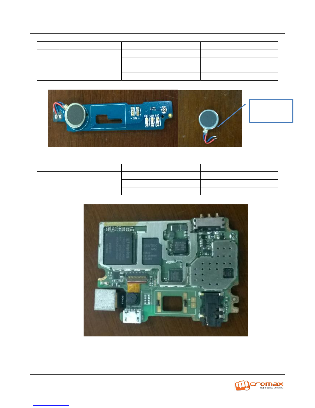
12) Vibrator
NO.
Description
Reason
Solution
1
No vibration
Soldering issue
Re-solde the vibrator
Vibrator issue
Change the Vibrator
CPU
Refer to L3 service manual
Assemble issue
Reassemble the vibrator
13) Playing Video
NO.
Description
Reason
Solution
1
Hang often
Software issue
Re-install software
CPU weld weakly
Repair MB
DDR weld weakly
Repair MB
Vibrator

A104 L2 Service Manual
14) Internet not working
NO.
Description
Reason
Solution
1
No signal
The coaxial cable assembly issue
Reassemble
GSM antenna assembly issue
Reassemble
SIM card broken
Change a new SIM card
RF IC issue
Refer to L3 service manual
Has no calibration
Re-calibrate
CPU
Refer to L3 service manual
15) Network
NO.
Description
Reason
Solution
1
No signal
The coaxial cable assembly issue
Reassemble
GSM antenna assembly issue
Reassemble
SIM card broken
Change a new SIM card
RF IC issue
Refer to L3 service manual
Has no calibration
Re-calibrate
CPU
Refer to L3 service manual
A104 L2 Service Manual
16) WI-FI/Bluetooth
NO.
Description
Reason
Solution
1
No signal
Wifi\BT antenna bracket assembly issue
Re-assemble
MB is broken
Refer to L3 service manual
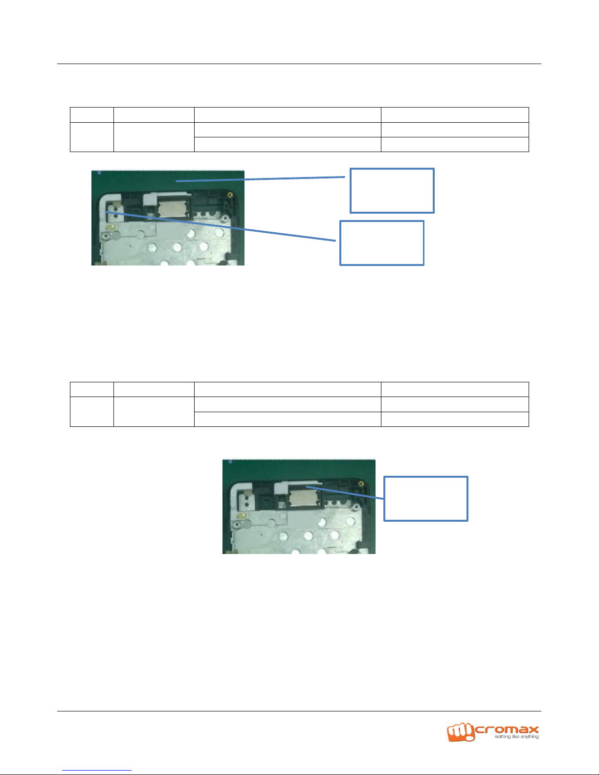
17) GPS
NO.
Description
Reason
Solution
1
No signal
Wifi\BT antenna bracket assembly issue
Re-assemble
MB is broken
Repair MB
Bluetooth
antenna
Wifi antenna
GPS antenna
bracket

A104 L2 Service Manual
18) FM/Radio
NO.
Description
Reason
Solution
1
No signal
Earphone issue
Change a new earphone
Earphone Jack of mainboard issue
Refer to L3 service manual
19) Earphone
NO.
Description
Reason
Solution
1
One side is not working
earphone issue
Change a new earphone
Cable broken
open the housing of MIC, check
and solder the cable
CPU or charging IC with issue
Refer to L3 service manual
2
Noise
Cable broken
Open the housing of MIC, check
and solder the cable
3
MIC is not working
MIC issue
Change the earphone
Cable broken
open the housing of MIC, check
and solder the cable
4
Can’t end the call by
earphone
Assembly issue
Open the MIC housing ,check
and assembly again
Earphone Jack

A104 L2 Service Manual
20) Loud Speaker
No.
Description
Reason
Solution
1
Noise/crack
The SPK with dust
Clean the SPK
Speaker foam issue
Change it
Speaker issue
Change it
CPU
Refer to L3 service manual
2
No volume/low volume
Connection issue
Assembly it again
Louder speaker issue
Change it
CPU
Refer to L3 service manual
Speaker

A104 L2 Service Manual
21) MIC
NO.
Description
Reason
Solution
1
Noise with uplink side
There is dust with MIC
Clean the MIC
Solder issue
Re-solder it
MIC issue
Change the MIC
The main LINK FPC assembly
issue
Reassemble the Link FPC
CPU or related component
Refer to L3 service manual
2
Volume low/no volume
with uplink side
There is dust with MIC
Clean the MIC
Solder issue
Re-solder it
MIC issue
Change the MIC
The main LINK FPC assembly
issue
Reassemble the Link FPC
CPU or related component
Refer to L3 service manual
3
TDD noise
MIC issue
Change the MIC

A104 L2 Service Manual
22) Receiver
NO.
Description
Reason
Solution
1
Noise/crack
There is dust with receiver
Clean the receiver
Receiver issue
Change it
CPU
Refer to L3 service manual
2
No voice/ volume low
Connection issue
Assembly it again
Receiver issue
Change it
CPU
Refer to L3 service manual
Receiver

A104 L2 Service Manual
23) Battery
NO.
Description
Reason
Solution
1
Show charging but it is not charged
Charging IC issue
Change PCBA
2
Cannot be full charged
Battery issue
Change the battery
Charging IC issue
Change PCBA
3
No charging
Charging IC issue
Change PCBA
Thanks
For any Query or suggestion, Please write to tech.help@micromaxinfo.com
Other cromax Cell Phone manuals


