cromax GC318 User manual

Model GC318 L3 Service Manual
1. Technical Specifications :
Particular
Remarks
Key Matrix For Flashing
N/A
Chipset
MTK6260A+QSC1110
Android Version
N/A
Processor Frequency
360MHz
Network Mode
GSM 900/1800 CDMA 800
GSM
64+0Mb
CDMA
128+32Mb
Internal memory
NA
Expandable Memory
8GB
Factory mode code
*#629#
Good Earpiece volume
Good Loudspeaker volume

Model GC318 L3 Service Manual
2. CAUTIONS
I. Flashing & Servicing must be undertaken by qualified personnel only.
II. Ensure all work is carried out at an anti-static workstation and that an anti-static wrist strap is worn.
III. Use only approved Tools & components as specified in the parts list.
IV. Ensure all components, modules, screws, and insulators are correctly re-fitted after servicing and alignment
V. Ensure all cables and wires are repositioned correctly if Handset disassembled
VI. Electrostatic discharge can easily damage the sensitive components of electronic products. Therefore,
Service Centre must take the precautions which mentioned above.
3. L3 Level trouble shooting
Trouble shooting/ Repairing steps against given below given symptoms
1) Doesn’t Power On...................................................
2) Restart / Hang.......................................................
3) LCD.......................................................................
4) Keypad....................................................................
5) Charging................................................................
6) USB.........................................................................
7) Main Camera..........................................................
8) Vibrator.................................................................
9) Network related issues/SIM related Issues.........
10) Bluetooth.............................................................
11) FM / Radio...........................................................
12) Outgoing Audio / MIC..........................................
13) Incoming Audio / Earpiece..................................
14) Speaker.................................................................
15) Memory Card.................................
Steps of Trouble Shooting with Images and Circuit Diagram
1. Doesn’t’ Power On
VBAT High Current
1. VBAT High Current: Analyses:VBAT provide power IC are MT6252, QSC1110,
2. GSM: PA-AP5200, CDMA: PA-BST3405, Charging protecting IC, LCD light, keypad light, Torch, SIM Card

Model GC318 L3 Service Manual
3. analog switch and so on
First method: Touch heat under High Current Through touch the heat components finding problem, after
charging in short time.
Second Method: Excluding method If can’t find problem,using excluding method. Take off components one by
one: Proceeding:take off LCD, keypad board, torch—> charging protects IC --> audio -->MT6260A
VBAT Connector
a) Press power key High Current
This defect cause of VDD, VCC supply power Shorting Problem
1. First take off connected components
2. Such as LCD and CAMERA
3. Then judge is CDMA module problem or GSM module problem
4. CDMA module problem judgment
5. CDMA module power on big electricity is usually from QSC1110 chipset and FLASH chipset,
Judge from which chipset is hot
6. GSM module power on big electricity,usually problem is MT6260 burn down
7. Touch CPU, FM chipset, sensor whether is hot judging problem
LCD Soldering Points Camera Soldering Points

Model GC318 L3 Service Manual
16)Restart / Hang
Steps:Auto power off, hang investigation
1. Check battery connecting well or not, battery protector circuit damaged or not;check the battery by millimeter.
2. Voltage whether is above 3.5V, if below 3.0V, battery is over drained damaged.
3. Check PCB and LCD whether have short circuit;
4. Check power on electricity status;
5. If upgrade sw can fix the problem. It is sw problem
6. CPU fake soldering,remove and re soldering
7.After above checking still can’t fix. It may be CPU problem. Change a CPU
Steps: Not power on checking procedure
Power on condition:have power, clock signal and Software these three conditions is the basic power on request
1. Check battery, keypad board, battery connecter is ok or not;test battery voltage by millimeter whether
above 3.7V ,battery connecter’s shrapnel whether is sinking leading to unconnected with battery;keypad
board FPC is broken.
2. check whether have fake soldering or damage on PCB, such as LCD short circuit or damage, camera,
speaker, motor short circuit they all can lead not power on if above two condition is all right, following
below procedure checking PCB(if no instrument, can change the components excluding)

Model GC318 L3 Service Manual
Steps: Call drop, draining check procedure
Call drop, drain and Leakage usually phenomenon are phone heat, short stand by. Ampere meter testing will
show High current, leakage. If don’t fix this defect, it will damage cell phone and battery
1, first check whether has soldering caused short circuit
2, call drop usually stand by calling, searching net drop,it is leading by RF circuit,RF PA defect;or battery
Protector board problem,lack of power
3, consumption, leakage can check the different power supplier pin resistance rate if un-normal resistance break
The power and load testing separately abnormal resistance rate is defection, change it.
4, Check the RF Section Shorting in PA
RF Section CDMA: Qualcomm Chipset
RF Section GSM: MTK Chipset

Model GC318 L3 Service Manual
3) LCD abnormal showing refer to LCD connector circuit
LCD Display Problem:
Phenomenon:
White LCD, No back LCD light, chaos showing or abnormal color。In maintain, first check LCD soldering,if FPC
damaged or soldering not well,change or re-soldering. If connect well,need check the LCD module,change good LCD
module testing. If it doesn’t work,check R612/R613/R614/R615 is fake soldering or not. After inspection the back light

Model GC318 L3 Service Manual
not working, should check the back light VBAT added on LCD connector. If back light also have problem, checking
VIO18/VIO28 If above all no problem,maybe PCB problem,usually CPU Dry soldering.
4) Keypad (keypad no function)
a) Refer to keypad connector circuit
Physical on Phone: Remove the Dome Sheet of Keypad to check by Multi-meter to Components

Model GC318 L3 Service Manual
Power On key:
Check the Value of Register Value
1, Check whether the whether the DOM in the correct position or not, if not you should
Change or re-attaché the DOM
2, if the DOM itself can working fine, now you should check the circuit line regarding
The keypad above image is for referencing.

Model GC318 L3 Service Manual
b) Keypad LED cannot lighten
Please check the resistance which the LED matches soldering properly. If the soldering has problem, just
Re-soldering. If soldering has no issue, then change the LED. Remove the Keypad Dome Sheet to test

Model GC318 L3 Service Manual
5)Charging
The phenomenon of charging issue is as below:
1, There is no charging animation on the LCD displaying.
2, There is a mistaken displaying while charging.
The steps of analyzing :
1. Change the charger
2. To check the USB comport whether the soldering is properly or not
3. Change the Charging protective IC
4. Change the Q202 (Mention on Components)
5. Change the CPU
Charging Section

Model GC318 L3 Service Manual
6)USB
USB connect to CPU directly, the phenomenon as below
PC Cannot read the USB, it can charges but cannot use as a disk
The analyzing steps:
1. Change the USB cable
2. Check whether the USB is damages or soldering properly
3. Change the CPU

Model GC318 L3 Service Manual
7)Main Camera
1. Check whether the camera soldering properly or not
2. Check the Camera module damaged or not
3. Change the Camera module
3. Check the camera power supplying
Model GC318 L3 Service Manual
4. Change the CPU
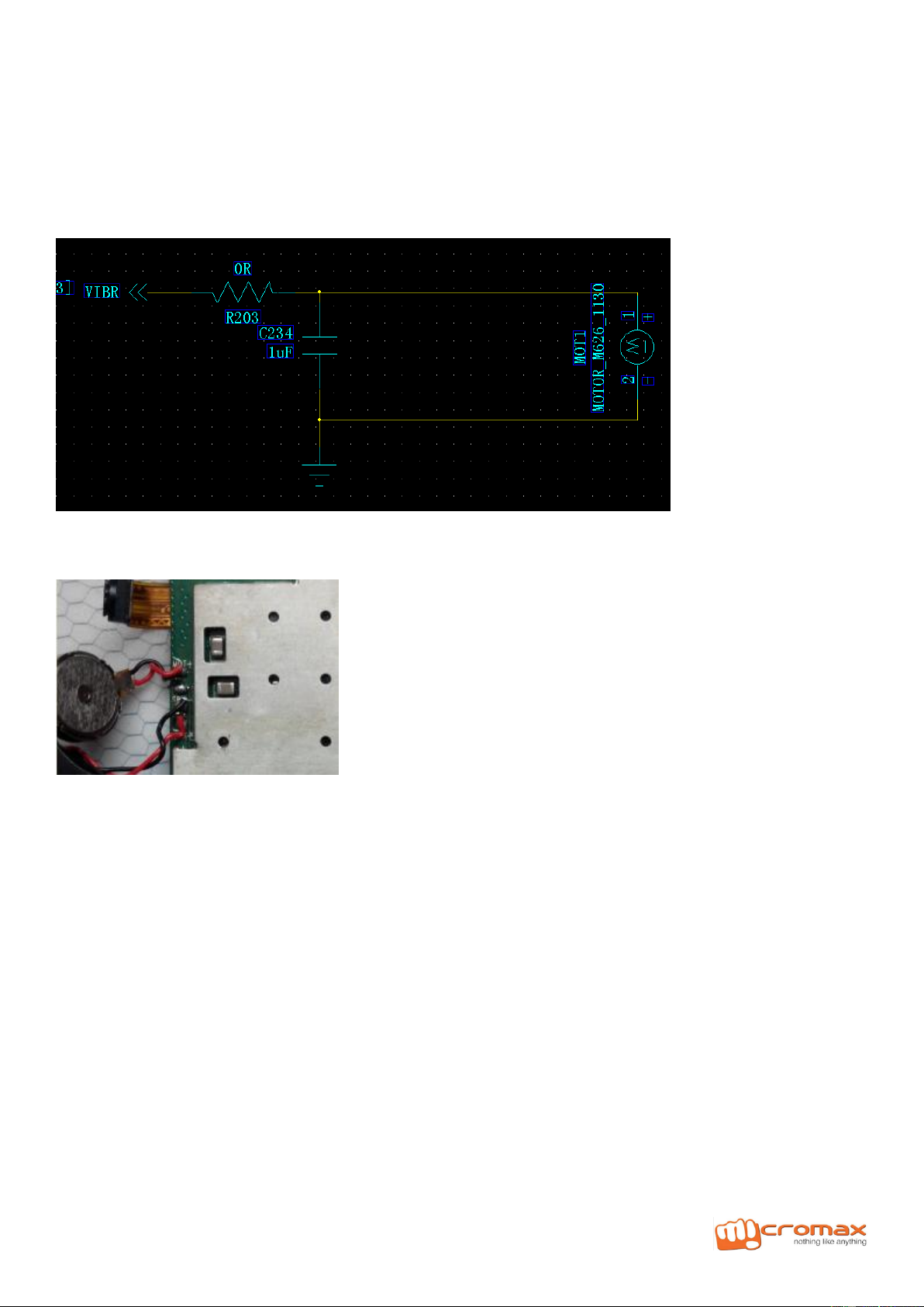
8)Vibrator
1. Check the soldering between Vibrator and PCBA is properly or not, if soldering has no issue, using the digital
power supply at 2 Volt position to check whether the Vibrator working fine or not .If Vibrator cannot work, then
change another one; if the vibrator working fine, it proves that the control signal has not reached at the
vibrator, you have to check the component on the trace leads to Vibrator (R203 and C234).
2. Replace the CPU or re-soldering CPU.
9)Network related issues/Sims related Issues
a)GSM SIM:
SIM card itself analyzing

Model GC318 L3 Service Manual
1. Check whether the SIM card is damaged
2. The component of card slot is damaged or not; whether the indication of inserting SIM card is correct or not
3. Check whether the power supply to SIM card is connected or not
1. Check whether the SIM card is clear enough to connect to the PCBA
2. Change another SIM card, if it can be detected, it proves that the previous SIM card is damaged.
CPU
1. If there is no issue about the card slot itself, then you have to check the around resistance and capacitance
soldering properly or not.
2.If the soldering has problem, you have to replace the replace or re-soldering .Finally you have to check the
signal SIM-CLK,SIM-DATA,SIM-RST-N(from CPU) and the voltage .
3. If the soldering has no issue, you have to check the signal path.
Once there is no problem about above 3 points, you have to re-soldering or replace the CPU.

Model GC318 L3 Service Manual
b)CDMA UIM:CDMA part can power on but cannot detect the UIM card
Insert UIM Card and power on the handset, if it is displaying “Insert UIM card “and can check the CDMA saw
version (you can input *#0000# to check the CDMA sw version ),it proves that the issue exist on the
Circuit parts

Model GC318 L3 Service Manual
Phenomenon 2: CDMA part cannot power on, it caused the UIM card cannot be detected:
Insert UIM card, and going to idle screen, if it can displaying “Insert UIM card”,but cannot check the
CDMA SW code by inputting *#0000#,it proves that CDMA part cannot power on.
STEPS:
1. Short circuit VBAT and VCHG to check whether the CDMA can power on or not. If it can power on, it proves
that the issue exists in the GC power key path.
2, Short circuit the VBAT and VCHG, if still cannot power on CDMA, it proves that the issue exists on the CDMA
itself. There is some possibility as below: High current, No current, current cannot be hold and the current is hold
at a certain step of powering on process only.
1)High current
Check VCHG, VBAT, S1,S2,VREG_MSMA, VREG_ MSME1, VREG_ MSME2,VREG-RUIM, VREG-RFA1,
VREG-RFA2, VREG_ MPLL,VREG_ XO whether the voltage is proper or not.
2)No current
1. Check the output voltage of CDMA CPU and check the soldering of resistance and capacitance, if there is
some problem about the soldering, just replace or re-soldering.
2. Try to download the SW
3. Current cannot be hold
4. Make the current of PS-HOLD high to hold the current, then check the XO(19.2MHz),VBAT, S1,S2,
VREG_MSMA, VREG_ MSME1, VREG_ MSME2, VREG-RUIM, VREG-RFA1, VREG-RFA2, VREG_ MPLL,
VREG_ XO voltage one by one,if the voltage is not proper, fine the reason, If the voltage is proper, then check
the CPU.
5. Current is holding in a certain process of powering on
Phenomenon 3 CDMA can power on but it is displaying searching network all the time.:
Inserted UIM card and power on the handset
displaying “Searching network” all the time
It proves that the UIM card is detected but the signal is
not good
Analyzing :
1, CDMA RF slot not connected ,need to re-soldering
Re-soldering
2, CDMA antenna touched not properly
Assemble the antenna again

Model GC318 L3 Service Manual
10)Bluetooth
BT fault:BT not Activating
Check antenna soldering well or not, C315/C314 soldering or not
BTAntenna
Can’t find other equipment, Change CPU
11)FM / Radio(FM circuit theory and maintain)
FM fault:FM no function, FM no channel, no sound output

Model GC318 L3 Service Manual
FM can’t receive channel maintain
1. Check earphone slot, soldering
2. Check whether in the no signal area
3. Check R712, R713 R121 R120 take off soldering
4. Change FM chipset
5. FM no function, change CPU
No sound output
AUDIO EARJACK
1. Check earphone audio Jack
2. Change the Components
If Still not Solve
3. Change CPU

Model GC318 L3 Service Manual
12)Outgoing Audio / MIC (MIC no sound maintain)
Check MIC first。If MIC is ok,check R471,R472 fake soldering or not,check TVS703,TVS704 soldering
reversed? C406,C408 short circuit with earth
1.confirm G net or C net no sound:
G net:
G net mica no sound, first check micbias0 whether is high voltage, C401, C501 damaged or not。
C net:
C net mic no sound, first check micbias0 weather is high voltage, C410\C425 damaged or not。
2. If above inspection no problem,check mic related circuit connectivity and components;excluding mic
components,still have problem,change cpu,G net mic no sound change MT6260,C net mic QSC1110
13)Incoming Audio / Earpiece(receiver no sound maintain)
A)receiver no sound maintain:

Model GC318 L3 Service Manual
Receiver no sound maintain
1. If receiver is damaged, change it。
2...check U402, B703 B704 is fake soldering or not。C708,C709 whether short circuit with earth,RV400,RV402
whether soldered reversed
3..check receiver’s circuit;after above , still have problem, change CPU
b)earphone maintain:
Other manuals for GC318
1
Other cromax Cell Phone manuals


