Cronos STAK Solar User manual

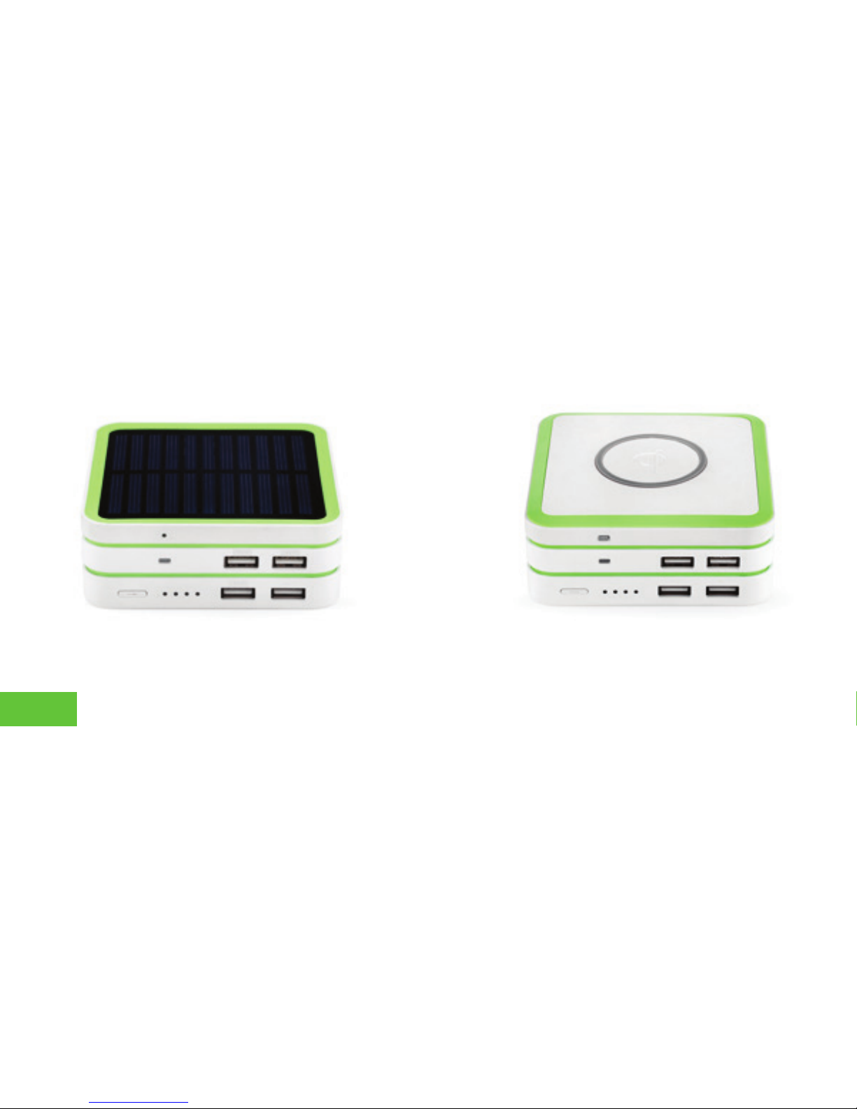
STAK Solar
STAK Wireless
User Guide
STAK Wireless
Model: ECS-PS12KW4
STAK Solar
Model: ECS-PS12KS4
2

TABLE OF CONTENTS
I. STAK package contents............................................................................4
II. STAK Power Module indicators/functions ................................................6
III. How to stack STAK Power Modules .........................................................9
IV. How to stack Solar/Wireless/Accessories Modules ................................10
V. How to charge (1) STAK Power Module .................................................11
VI. How to fast charge a stack of STAK Modules......................................... 12
VII. How to charge your mobile device with STAK.......................................13
VIII. How to charge with STAK Wireless or Solar...........................................14
IX. STAKspecifications.................................................................................15
X. STAK warranty & warnings......................................................................17
3

I. STAK PACKAGE CONTENTS
1
5 6 7 8
2 3 4
4

1. Main Power Module
2. Main Power Module
3. Solar Module
4. Wireless Module
5. Charge Base
6. AC/DC Adapter
7. Smart LED Lighting Connector
8. Smart LED Micro USB Cable
NOTE 1. Solar Module is included with Model ECS-PS12KS4. Wireless Module is
not included in this model.
NOTE 2. Wireless Module is included with Model ECS-PS12KW4. Solar Module
is not included in this model.
NOTE 3. Instruction manual is included with each STAK Power Station model.
NOTE 4. Power Stations do not include iPod, iPhone, iPad or any USB
configuredmobiledigitaldevice.
5
7
8
109
3
2
1
4 5
6
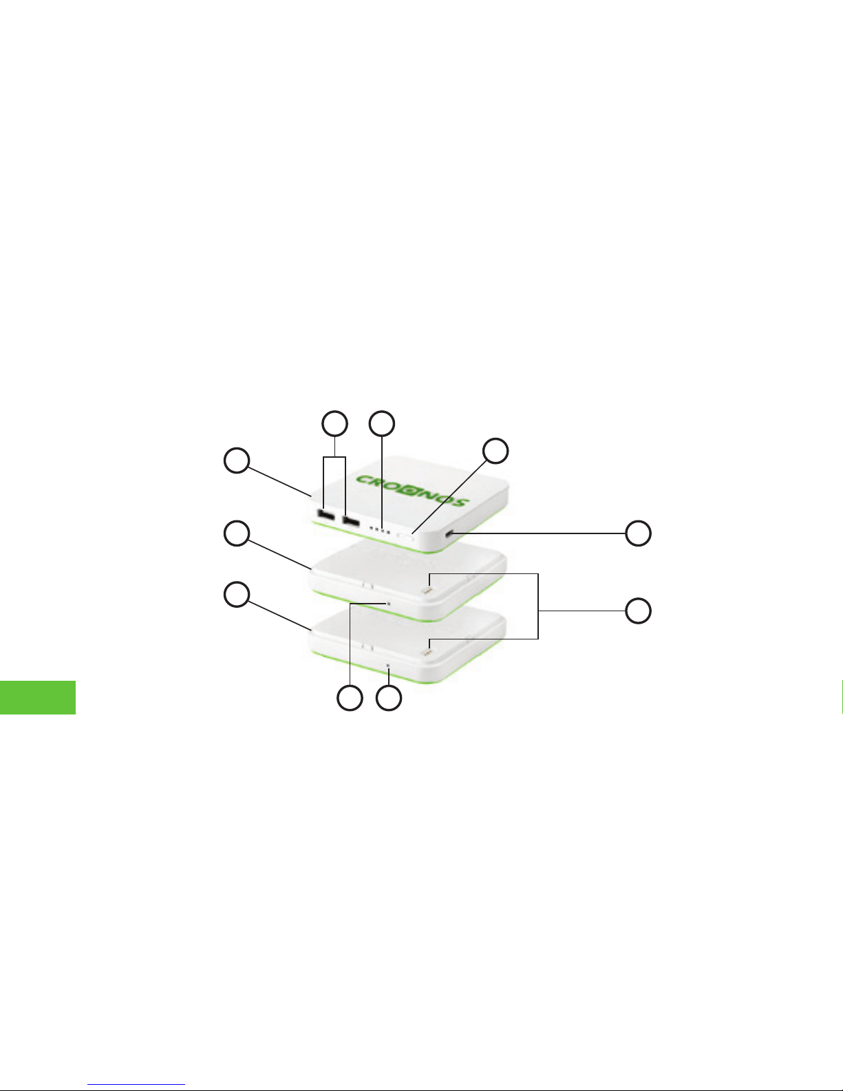
II. STAK POWER MODULE INDICATORS/FUNCTIONS
6
4. USB OUTPUT PORTS [2]
6. LED INDICATOR BUTTON
5. MAIN POWER MODULE INDICATOR
Both USB Ports support up to 2.1A output speeds. Power
iQ & Auto-Detect Technology sense and automatically
apply the proper power needed by iOS mobile platform
andotherUSBcongureddevices.
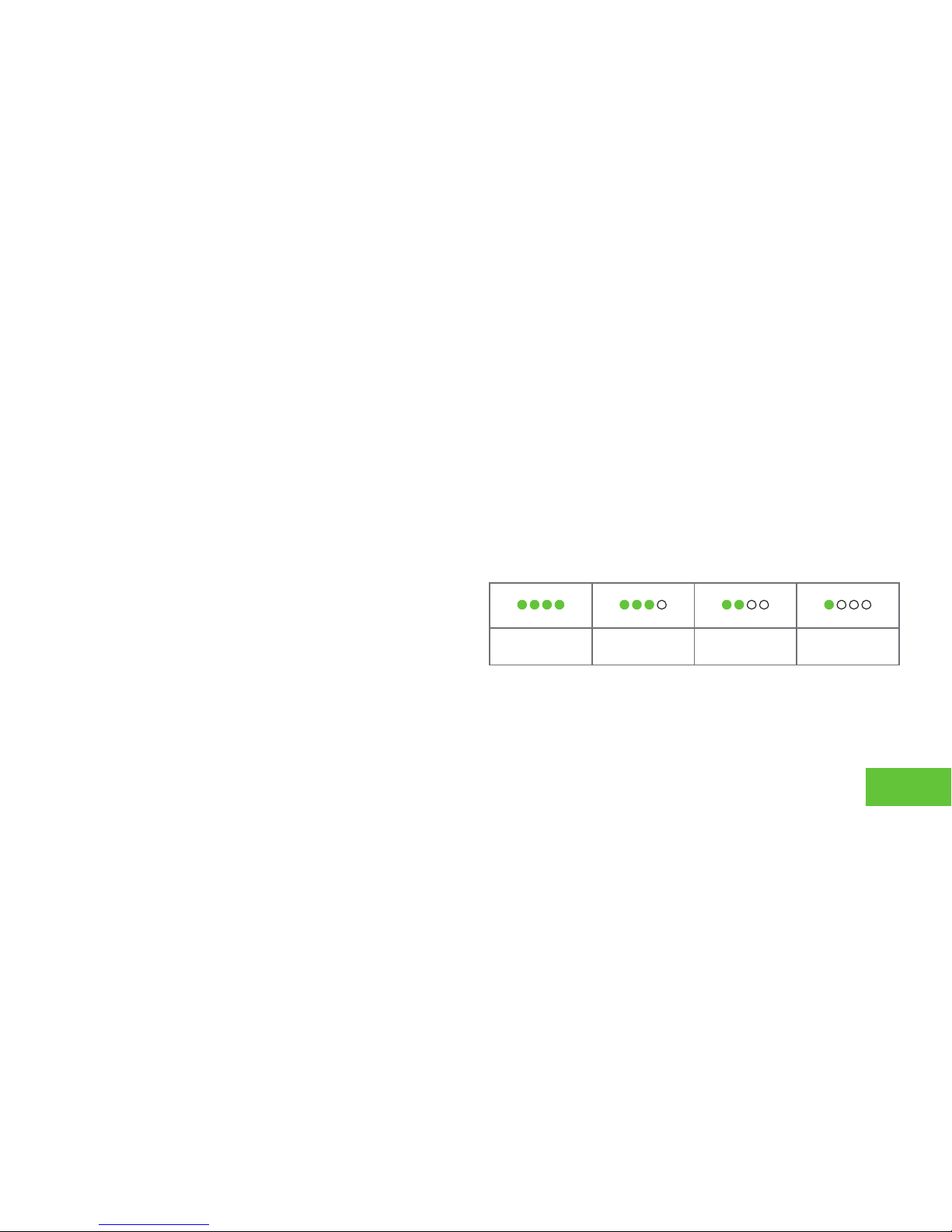
Indicates charging and in tandem with the 4 LED indicator
buttons to show amount of power that is available in the
Main Power & Sub-Power Modules.
1. MAIN POWER MODULE
Controls input, output, and auto-detects the power
volume of the Main Power Module and Sub-Power
Modules. Includes built-in 6000mAH (milliamp hours)
polymer battery.
2. MAIN POWER MODULE
Power expansion module. Includes built-in 6000 mAH
Lithium polymer battery.
3. SOLAR MODULE
Monocrystalline silicon matt solar module automatically
activated during ideal sunlight conditions to assist Main
Power & Sub-Power Modules in charging iOS module
platormandotherUSBcongureddevices.
75 - 100% 50 - 75% 25 - 50% 0 - 25%
7

10. SOLAR MODULE INDICATOR
8. PARALLEL CONTACTORS
7. INPUT PORT
Micro USB port used to charge Main Power Module .
Max power input: 5V/2A by connecting with Micro
USB included cable.
9. MAIN POWER MODULE INDICATOR
Conrmsthatthemodulesaresecurelyconnectedand
indicates power capacity.
Green indicates battery capacity is between
70 - 100%.
Blue indicates battery is between 40 - 70%.
Red indicates the battery capacity is between 5 - 40%.
Indicates the working status of the Solar Module.
Positive contact for connection and communication
between Main Power Module, and Solar Module.
Negative contact for connection and communication
between Main Power Module, Solar Module.
Communicating Now.
C
8

III. HOW TO STACK STAK POWER MODULES
1. StartbyplacingaMain PowerModule (4 LEDs + 2 USB ports) onafl
atsurfacewiththegreen side facing down and the Croonos brand facing
up. Take a Main Power Module (4 LEDs + 2 USB ports) and place it on top
of another Main Power Module.
2. Make sure to align the gold contacts on the top of the first Main
Power Module with the gold contacts on the bottom of the second Main
Power Module as shown in the illustration to the left.
3. AfterconfirmingproperalignmentofthegoldcontactsofeachMain
PowerModule,simplysnapfitthe2modulestogethersothattheyare
lockedintoplace.
4. If you require additional power capacity beyond the two (2) Main
Power Modules(6000mAh each), simply stack additional Main Power
Module on the bottom of the initial set of Main Power Modules. 9
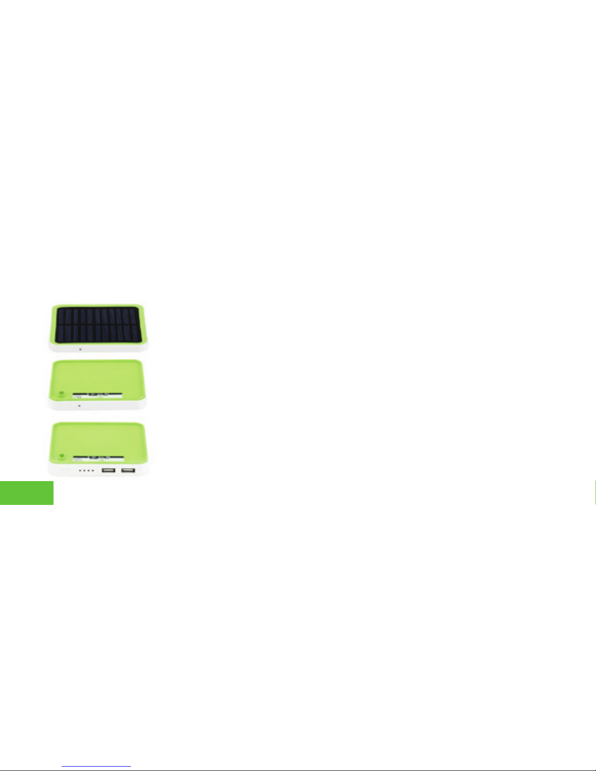
IV. HOW TO STACK SOLAR/WIRELESS/ACCESSORYMODULES
1. Start by placing a Solar Module or Wireless Module, on top of a Main
Power Module as shown in the illustration to the left. Makesurethatthe
PowerModulesareflippedwiththegreensidefacingup.
2. Make sure that the 3 gold contacts on the bottom of the Solar or
Wireless Module and the 3 gold contacts on the Power Modules are aligned
as shown in the illustration to the left for a proper connection of STAK Power
Modules.
3. Once the 3 contacts on the bottom of the Solar Module or Wireless
Module are properly aligned with a Main Power Module,snapfitallofthe
modulestogethersothattheylockintoplace.
4. If you require additional power capacity beyond two (2) Main Power
Modules(6000mAh each), simply stack additional Main Power Modules to
the bottom of the stack.
10

1. When you are on the road and without STAK
Charge Base, you can still charge Stak’s Main
Power Modules. Please locate the Micro USB port
on the side of STAK Main Power Module or Eco-
Device Accessory Module.
2. Use the supplied Micro-B Smart LED USB cable
by connecting the Micro-B connector to the Micro
USB port of the Main Power Module as shown in
the illustration to the left. Take the USB end of the
cable and connect it to the USB port of your
mobile phone charger or the USB port of your
laptop or desktop.
V.HOW TO CHARGE STAK POWER MODULES
11
4. You can also use the supplied Micro-B Smart LED cable by connecting the
Micro-B connector to the Micro USB port on the back of the charge base
and connecting the USB connector to your laptop USB port or to the USB
port of your mobile device charger.
VI. HOW TO FAST CHARGE A STACK OF STAK MODULES
1. Stack multiple sets of the Main Power Moduleson top of the included
Charge Base using the same stacking method in Section III, How to stack
power modules.
2. Locate the included 18W AC/DC adapter and connect it to the round
12V/DC port on the back of the Charge Base. Insert the Adapter’s US
configuredplugintoanACwalloutlet.
3. Once the provided 18W AC/DC adapter is properly connected to an
AC wall outlet and the Charge Base, the LED light on the front of the
ChargeBasewillbeginflashingbluecoloruntilitstopswhenfull.
12

4.ForAndroidUSBconfigureddevices,pleaseselecttheMicro-BSmartLEDUSBcableprovided.STAK
Micro-BSmartLEDcablesalsoserveasachargestatusindicator.TheSmartLEDflashesredwhen
charging,flashesbluewhenreachingfullcharge,andturnsstaticbluewhenfullstateofchargeisreached.
VII. HOW TO CHARGE YOUR MOBILE DEVICE WITH STAK
1. STAK Main Power Modules are equipped with two (2) 2.1A high
speed USB ports for charging most Tablets, Mobile Phones, and Smart
Phones simultaneously.
2. Each USB port is engineered with Auto-Sensing Technology enabling
automatic detection of the appropriate charging credentials needed to
properlychargeUSBconfiguredmobiledigitaldevicesatoptimalcharge
rates.
13
3. For iOS USB devices, please select the Smart LED 8 pin MFi Lightning connector provided. STAK Lightning
Smart LED cables also serve as a charge status indicator. The Smart LED flashes red when charging, flashes
blue when reaching full charge, and turns static blue when full state of charge is reached.

1. IfyoupurchasedSTAKPowerStationSolar,youhavetheoptionofchargingyourUSBconfigured
mobile device via the Lithium Polymer Battery Technology that is embedded in each Power module or
when outdoor conditions are optimal you can charge your mobile device using the power of natural
sunlight.
2. STAK Solar Power Station is equipped with a Monocrystalline Solar Module that can charge your
mobile digital device using the green power of the sun. Use the appropriate Smart LED Cable provided
for your mobile device to connect to the USB port on the Main Power Module or Sub-Power Module
and you are now charging by Solar energy.
3. If you purchased STAK Power Station Wireless, you have the option of charging your USB configured
mobiledeviceviaourembeddedLithiumPolymerBatteryTechnologyineachPower Module or by Qi
Wireless technology.
4. STAK Wireless Power Station is equipped with a Qi Wireless Transmitter. If you have a Qi
enabled mobile device you simply place the mobile device on top of STAK’s Wireless Module
and charging is automatically executed.
VIII.HOW TO CHARGE WITH STAK WIRELESS OR SOLAR
14

Battery Capacity (Total) 12000 mAH
• Main Power Module 6000 mAH
• Sub-Power Module 6000 mAH
USB Input 5V/2A
Total USB Output 5V/4.2A
USB Output 1 , 2 5V/2.1A , 5V/2.1A
Wireless (Input , Output) 5V/2.1A , 5V/1.0A
Solar (Input , Output) 5V/2.1A , 5.5V/100mA
Battery Technology Lithium Polymer
Grade A Cells
Input Charge Time 1 6000 mAH, 6 hours by
micro USB Input
Input Charge Time 2 6000 mAH, 2 hours by
charge base
Dimensions
• Main Power Module
3.90”x3.90”x0.47”
(99x99x12mm)
Dimensions
• Sub-Power Module
3.90”x3.90”x0.39”
(99x99x10mm)
Dimensions
• Wireless Module
3.90”x3.90”x0.39”
(99x99x10mm)
IX. STAK SPECIFICATIONS
15

Dimensions
• Solar Module
3.90”x3.90”x0.24”
(99x99x06mm)
Dimensions
• Charge Base
4.72”x4.72”x0.78”
(120x120x20mm)
Weight
• Main Power Module
0.30lbs (138g)
Weight
• Sub-Power Module
0.26lbs (116g)
Weight
• Wireless Module
0.19lbs (88g)
Weight
• Solar Module
0.09bs (40g)
Weight
• Charge Base
0.33lbs (150g)
Housing Material LG imported scratch
proof, non-color
fading,reproof
ABS/PC
16

Physical damage of this nature to any product purchased at croonos.com will constitute misuse and effectively
void warranty coverage. Shipping charges are non-refundable. croonos.com. does not allow any refunds for
X. STAK WARRANTY & WARNINGS
WARRANTY
At croonos.com we consider our customers as an important family asset of our user ecosystem that we are building. We
arecommittedtoprovidingourfamilyofuserswith100%satisfaction.Therefore,ifPurchaserisnotsatisedwithany
croonos.com. product, Purchaser may return it within 30 days for replacement or refund as long as the returned item is
in the exact factory condition that it was sold to Purchaser. A 15% restocking fee may be applied to all returns for refund.
Claims for missing items must be received within two (2) business days of receipt of merchandise. In the event that
croonos.com. is unable to repair or replace your product (due to availability, end of life, or other), a like model or credit
towards other croonos.com. products will be offered by our technical support staff.
Croonos.com. warrants, for a period of one (1) year from the date of the original purchase, that your product shall be free
of defects in design, material, or manufacturing to the original Purchaser. This warranty is limited to repair or replacement
oftheproduct.Croonos.com.willrepairorreplace,atitssoleandabsolutediscretion,anyproductconrmedtobe
defective by our technical support team. This warranty excludes damages for a purpose in which it is not intended,
resultingfromimproperuseormaintenance,Purchasermodications,abuse,damage,accident,normalwearandtear.
17

product/s purchased by the Purchaser at croonos.com after 30 days from the date of invoice or receipt. The croonos.
com. warranty only applies to products purchased as new, which must be purchased directly from croonos.com. or
any authorized retailer. croonos.com. reserves the right to review any croonos.com. product considered for warranty
coverage. All costs of shipping the product to croonos.com. for inspection shall be the responsibility of the“Purchaser”.
CROONOS.COM. MAKES NO OTHER WARRANTY, EITHER EXPRESS OR IMPLIED, WITH RESPECT TO THE PRODUCT.
CROONOS.COM SPECIFICALLY DISCLAIMS THE IMPLIED WARRANTIES OF MERCHANTABILITY AND FITNESS FOR A
PARTICULAR PURPOSE. AS A RESULT, THE PRODUCT IS SOLD “AS IS” AND YOU ARE ASSUMING THE ENTIRE RISK
AS TO THE PRODUCT’S SUITABILITY TO YOUR NEEDS. THE REMEDIES PROVIDED HEREIN ARE THE PURCHASER’S
SOLE AND EXCLUSIVE REMEDIES. IN NO EVENT SHALL Croonos.com. BE LIABLE FOR DIRECT, INDIRECT, SPECIAL,
INCIDENTAL OR CONSEQUENTIAL DAMAGES, WHETHER BASED ON CONTRACT, TORT, OR ANY OTHER LEGAL
THEORY.
WARNINGS!
1. Do not store this device in a high temperature environment, including heat caused by intense sunlight. Do not place
deviceinreorotherexcessivelyhotenvironments.
2. Be cautious of excessive drops, bumps, abrasions or other impacts to this device. If there is any damage to the
device such as dents, punctures, tears, deformities or corrosion, due to any cause, discontinue use, and contact
“Manufacturer” or dispose of the device to a proper battery recycling center.
18

3. Do not disassemble this device or attempt to use other than the intended use mode as described in the instruction
manual or modify it in any manner.
4. Do not expose this device to moisture or submerge it in liquid. Keep device dry at all times.
5. If this device is intended by “Purchaser” to be used by a minor, “Purchaser” agrees to provide detailed instructions
and warnings to any minor prior to use. Failure to do so is the sole responsibility of “Purchaser”, who agrees to indemnify
“Manufacturer “for any unintended use/misuse by a minor.
6.Alldeviceshavegonethroughathoroughandhighlyintensivequalityassuranceinspection.Ifyoundthatyour
device is excessively hot, is emitting odor, is deformed, damaged in any way, cut or is experiencing or demonstrating an
abnormal phenomenon, immediately discontinue use of the device and contact “Manufacturer”.
7. This product contains chemicals that are known to the state of California to cause cancer and birth defects or other
reproductive harm.
19

Designed by Croonos, LLC.
40 Central Park South, # 4A
New York, NY 10019
Made in China
REV013016
This manual suits for next models
3
Table of contents


