Cronyx E1 - L/S User manual

© 2006 Cronyx
Modem-Converter
E1 - L/S
19-inch 1U High Version
Installation and Operating Manual
Document Version: 2.2E / 06.09.2006

2Modem-Converter E1-L/S
© 2006 Cronyx
Safety Precautions
An exclamation point enclosed in a triangle warns the user about important
operations and maintenance instructions for the device.
It is mandatory to observe the existing safety rules during installation, operation,
and maintenance of the device. Installation, maintenance, and repair operations must
be performed only by qualied and certied personnel. Installation, maintenance,
and repair operations may not be performed by the operator or the user.
e E1-L equipment has been tested in the Communications hardware and sys-
tems testing center of CNIIS of the Ministry of Communications of the Russian
Federation and in the Sviaz’–Certicat quality systems certication centre and has
been acknowledged to comply the following technical specications:
•«Technical requirements for the hardware of the exible multiplexor (multifunc-
tional channelizing equipment with exible conguration ability)», approved
by the Ministry of Communications of the Russian Federation at February 20,
1997;
•GOST R ISO 9001-96.
e E1-L equipment is admitted to be used in domestic and intrazone commu-
nication networks of the Russian Federation as a multifunctional channelizing
equipment.
© 2006 Cronyx
3
Firmware revision
is document describes the E1-L/S version of the E1-L Modem. e E1-L/S version is
the 1U high rack mount device for the standard 19-inch cabinet.
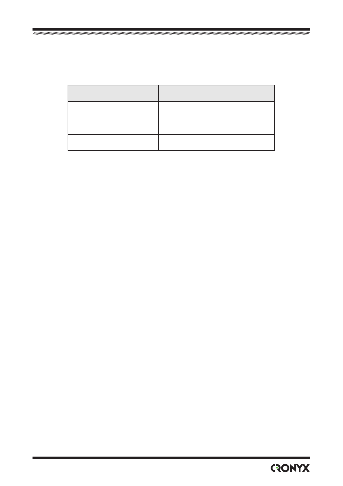
is document corresponds to the models with the rmware revision as follows:
Model identication Firmware revision
E1-L/S - ETV revision F, 13/04/2005
E1-L/S - V revision F, 13/04/2005
E1-L/S - M revision F, 13/04/2005
Cronyx reserves the right to make changes to technical characteristics and design of
the device without the prior notification of customers.

4Modem-Converter E1-L/S
© 2006 Cronyx
Contents
Chapter 1. Introduction...................................................6
1.1. Application............................................................................................... 6
1.2. Operation.................................................................................................. 7
1.3. Ordering Information ............................................................................... 8
1.4. Technical Specications........................................................................... 8
E1 Link Interface ..................................................................................... 8
Digital Port Interface: V.35/RS‑530/RS‑232/X.21 .................................. 9
Digital Port Interface: Ethernet 10/100Base-T ........................................ 9
Alarm Port Interface ................................................................................ 9
Console Port Interface ............................................................................. 9
SNMP Port Interface.............................................................................. 10
Diagnostic Modes .................................................................................. 10
Mechanical Characteristics.................................................................... 10
Power Requirements.............................................................................. 10
Environmental Characteristics............................................................... 10
Section 2. Installation....................................................11
2.1. Site Requirements ...................................................................................11
2.2. Delivered Items.......................................................................................11
2.3. Connections.............................................................................................11
Power Connection.................................................................................. 12
Ground Terminal.................................................................................... 12
E1 Link Connector................................................................................. 13
Ethernet 10/100Base-T Port and SNMP Port Connectors ..................... 13
Digital Port (V.35 / RS‑530 / RS‑232 / X.21) Connector ...................... 14
Digital Port (V.35) Connector................................................................ 15
Console Port Connector......................................................................... 15
Alarm Port Connector............................................................................ 16
Chapter 3. Operation.................................................... 17
3.1. Front Panel Indicators ............................................................................ 17
3.2. Synchronization Modes.......................................................................... 20
DTE Emulation...................................................................................... 21
DTE emulation, external transmit clocks ...................................... 21

© 2006 Cronyx
5
Contents
DTE emulation, external transmit and receive clocks................... 22
HDLC Buffer Mode............................................................................... 22
3.3. Alarm Conditions ................................................................................... 24
3.4. Loopbacks .............................................................................................. 25
Normal State (No Loopbacks Enabled)................................................. 25
Local Link Loopback............................................................................. 25
Remote Link Loopback ......................................................................... 26
Digital Port Loopback............................................................................ 26
3.5. Built-in BER Tester................................................................................ 26
Link Testing: Remote Link Loopback Enabled..................................... 27
Link Testing: Two Ber Testers Enabled Against Each Other................. 28
Section 4. Control From the Console ......................... 29
4.1. Upper Level Menu ................................................................................. 29
4.2. Menu Structure....................................................................................... 32
4.3. «Statistics» Command............................................................................ 33
4.4. «Event counters» Command .................................................................. 35
4.5. «Loopback» Menu ................................................................................. 37
4.6. «Test» Menu........................................................................................... 38
4.7. «Congure» Menu ................................................................................. 39
«Link» Menu ......................................................................................... 39
«Port» Menu for V.35 / RS-530 / RS-232 / X.21 Digital Port............... 41
Synchronous Mode ........................................................................ 41
Asynchronous Mode...................................................................... 42
«Port» Menu for Ethernet 10/100Base-T Port....................................... 43
«SNMP» Menu ..................................................................................... 44
«Sensor input» Command...................................................................... 45
«Factory settings» Command ................................................................ 45
«Save parameters» Command ............................................................... 46
«Restore parameters» Command........................................................... 46
4.8. «Link remote login» Command ............................................................. 47
4.9. «Reset» Command ................................................................................. 47
Section 5. SNMP-based Management......................... 48
5.1. SNMP Parameters Setting...................................................................... 48
5.2. Management Information Blocks (MIBs).............................................. 49
6Modem-Converter E1-L/S
© 2006 Cronyx
Chapter 1. Introduction
1.1. Application
e E1-L device is a modem-converter for E1-based networks.
Note. Hereinaer the term «E1» is used for a designation of the data link having the interface
at nominal bit rate of 2048 kbps in conformity with the ITU-T Recommendation G.703,
and operated in both framed mode in conformity with the ITU-T Recommendation G.704
(or with the IKM-30) and unframed (transparent) mode.
is document describes the E1-L/S version of the E1-L Modem. e E1-L/S version
is the 1U high rack mount device for the standard 19-inch cabinet. E1-L device is also
available as stand-alone unit (E1-L/B), as a card for 19-inch 3U Cronyx rack (E1-L/R)
and as a card for Intel-compatible computers (Tau-PCI/E1).
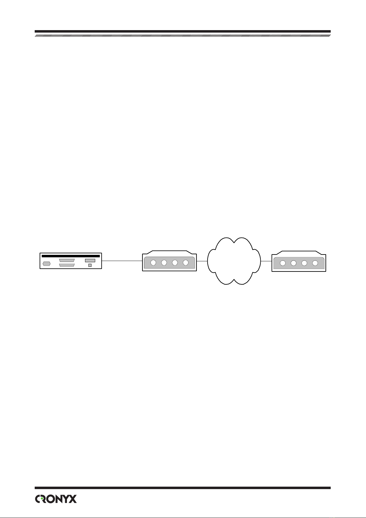
E1-L
E1-based
Network
Router
V.35 / RS-530 /
RS-232 / X.21
E1-L
e E1-L device accepts digital interface data at any multiple rate of 64 kbps up to 2048
kbps and places it into E1 frame using required number of timeslots or (in unframed
mode) the whole bandwidth of 2048 kbps.
e E1-L device may be ordered with Ethernet10/100Base-T, RS-530, RS-232, V.35 or
X.21 interfaces with standard connectors.
Note. Hereinaer the term «Ethernet 10/100Base-T» is used for a designation of the data
link having switcheble or autodetecting LAN interface 10BASE-T or 100BASE-T (phisical
level 100BASE-TX) in conformity with the IEEE 802.3 Standard.
Multi-standard interface option with HDB44 connector is also available. e type of
interface in this case is determined by adapter cable: RS-232, RS-530, RS-449, RS-442,
V.35 or X.21.
is document describes the E1-L/S version of the E1-L Modem. e E1-L/S version is
the 1U high rack mount device for the standard 19-inch cabinet.
E1-L device is also available as stand-alone unit (E1-L/B), as a card for 19-inch 3U Cronyx
rack (E1-L/R) and as a card for Intel-compatible computers (Tau-PCI/E1).
A pair of devices with Ethernet 10/100Base-T interface form a remote bridge for two

© 2006 Cronyx
7
Chapter 1. Introduction
LANs. While in unframed mode the E1-L modem may be used together with the PCM2
modem.
VLAN support is provided by implementing of Ethernet packets with the length enlarged
to 4224 bytes.
e device operation may be controlled from the console (ASCII terminal connected to
the RS-232 control port). e device is equipped with the dedicated Ethernet 10Base-T
port to support SNMP-based management.
e modem’s front panel indicators display the channels availability, loopbacks enable
and testing modes.
e built-in BER-tester allows the error level measurement in the E1 link. e meas-
urements are performed on the xed or pseudorandom code subject to the ITU-T
Recommendation O.151 guidelines (supported length of sequence is 215-1=32767
bits).
ere is a capability of remote login to control the remote device operation from the
console port of the local device (this mode may be useful if there is no service person-
nel on the remote end of the link). Commands are transmitted to the remote device
via additional monitoring channel. is channel utilizes special bit of the timeslot 0 (in
accordance with the ITU-T Recommendation G.704) or any other user selectable bit
of any timeslot other than 0. e remote login capability is not supported in unframed
mode of operation.
e device is equipped with an emergency alarm relay. e state of the relay on the lo-
cal device depends on fault conditions detected and may be controlled from the remote
device. e relay operates in «dry contacts» mode and may be used for prompt mainte-
nance (according to the ITU-T Recommendations G.742 and G.751).
e rmware of the device may be updated by user. e instructions for updating the
rmware may be found at the www.cronyx.ru web site.
1.2. Operation
Data accepted from the digital interface port is placed into selected timeslots of the E1
stream for output through the E1 link. Unused timeslots are lled by ones.
Data retrieved from the selected timeslots of the E1 stream accepted from the E1 link is
transferred to the output of the digital interface port. Unused timeslots are ignored.
User may choose to disable E1 frame structure. In this case the whole bandwidth of
2048 kbps will be used for data transfer (bit data rate at the digital interface port may be
limited if required).

8Modem-Converter E1-L/S
© 2006 Cronyx
1.3. Ordering Information
E1-L / S —ETV —SNMP —AC
Power supply:
AC — 176...264 VAC
DC — 36...72 VDC
Digital port:
ETV — Ethernet 10/100Base-T
V — V.35
M — multistandard (V.35/RS-530/RS-232/X.21)
SNMP port:
dedicated Ethernet 10Base-T
port for SNMP-based
management
Version:
S — 1U rack mount for 19-inch
cabinet
1.4. Technical Specications
E1 Link Interface
Nominal bit rate..............................................2048 kbps
Connector........................................................RJ-48 (8-wire socket)
Coding .............................................................HDB3 or AMI
Framing............................................................ Framed mode: frame structure in accor-
dance with the ITU-T Recommendation
G.704; multiframes: CRC4, CAS (G.704).
Unframed mode: transparent stream trans-
mission without framing
Error monitoring............................................Code violation
Frequencies oset adjustment ......................Controlled slip buers on input
Transmit timing source .................................Internal oscillator, E1 receiver, digital in-
terface
Line impedance............................................... 120 Ohm symmetric (twisted pair)
Receiver signal level .......................................From 0 up to –43 dB
Jitter attenuation.............................................Both in receive and transmit path, up to
120 UIpp attenuation
Surge protection..............................................TVS
Over-current protection ................................Safety fuse

© 2006 Cronyx
9
Chapter 1. Introduction
Digital Port Interface: V.35/RS-530/RS-232/X.21
Data transfer rate.............................................from 64 up to 1984 kbps (N x 64 kbps) in
framed mode or up to 2048 kbps in un-
framed mode
Clock options ...................................................TXC, RXC, ETC, ERC
Modem control signals ...................................DTR, DSR, CTS, RTS, CD
Connector type ................................................Multistandard interface (V.35 / RS-530 /
RS-232 / X.21): HDB44 (female);
V.35 interface: M-34 (female);
RS-530/RS-232 interface: DB25 (female);
X.21 interface: DB15 (female)
Digital Port Interface: Ethernet 10/100Base-T
Interface type ...................................................IEEE 802.3 10BASE-
T/100BASE-T(100BASE-TX)
Connector type ................................................RJ-45 (8-wire socket)
Bandwidth ........................................................from 64 up to 1984 kbps (N x 64 kbps) in
framed mode or up to 2048 kbps in un-
framed mode
Operating mode...............................................100 Mbps, full duplex;
100 Mbps, half duplex;
10 Mbps, full duplex;
10 Mbps, half duplex;
autonegotiation
MAC address table size...................................15000 MAC addresses
Maximum packet size .....................................4224 bytes, including MAC level header
Protocol.............................................................Transparent or
Cisco-HDLC bridging IEEE protocol,
selectable automatically
Alarm Port Interface
Connector type .....................................................DB-9 (female)
Relay contact current ...........................................Up to 600 mA
Relay contact voltage............................................Up to 110 VDC or up to 125 VAC
Console Port Interface
Interface type, connector type ...........................RS-232 DCE, DB-9 (female)

10 Modem-Converter E1-L/S
© 2006 Cronyx
Data transfer mode...............................................Asynchronous, 9 600 baud, 8 bits per
character, 1 stop bit, no parity
Modem signals......................................................DTR, DSR, CTS, RTS, CD
SNMP Port Interface
Interface type ........................................................Ethernet 10Base-T
Connector type .....................................................RJ-45 (8-wire socket)
Diagnostic Modes
Loopbacks.........................................................Local on E1 link, remote on E1 link, lo-
cal on digital port (excluding Ethernet
10/100Base-T port)
Error rate measurement..................................Built-in BER tester
Control..............................................................Via the console port, from a remote de-
vice, via the SNMP port
Mechanical Characteristics
Construction ....................................................1U high rack mount metal enclosure for
19-inch cabinet
Dimensions ......................................................444 mm × 262 mm × 44 mm
Weight...............................................................3.4 kg
Power Requirements
AC supply voltage............................................176–264 VAC, 50 Hz (for the «-AC» ver-
sion)
DC supply voltage ...........................................36–72 VDC (for the «-DC» version)
Max. power consumption...............................20 VA
Environmental Characteristics
Temperature .....................................................0 to 50 °C
Relative humidity ............................................Up to 80%, non-condensing
© 2006 Cronyx
11
Section 2. Installation
Section 2. Installation
2.1. Site Requirements
e device should be grounded properly before powering on. Grounding screw located
on the front panel of the device.
Allow at least 10 cm clearance at the front of the device for cable connections.
e ambient operating temperature should be 0 to 50 °C, at a relative humidity of up to
80%, non-condensing.
2.2. Delivered Items
E1-L/S unit of a version as ordered......................................................1 piece
Bracket for mounting the E1-L/S unit in a 19-inch cabinet .............2 pieces
Self-adhesive foot for the E1-L/S unit..................................................4 pieces
Power cable (for the «-AC» version)....................................................1 piece
3-screw removable terminal block (for the «-DC» version).............1 piece
is Installation and Operating manual .............................................1 piece.
2.3. Connections
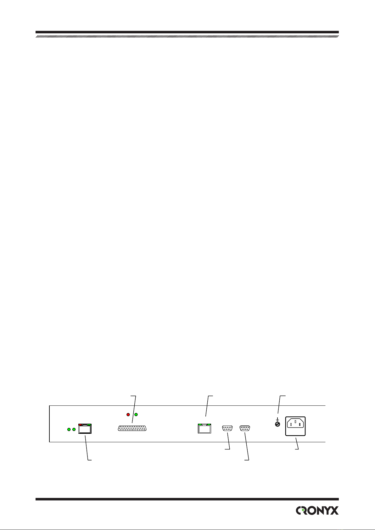
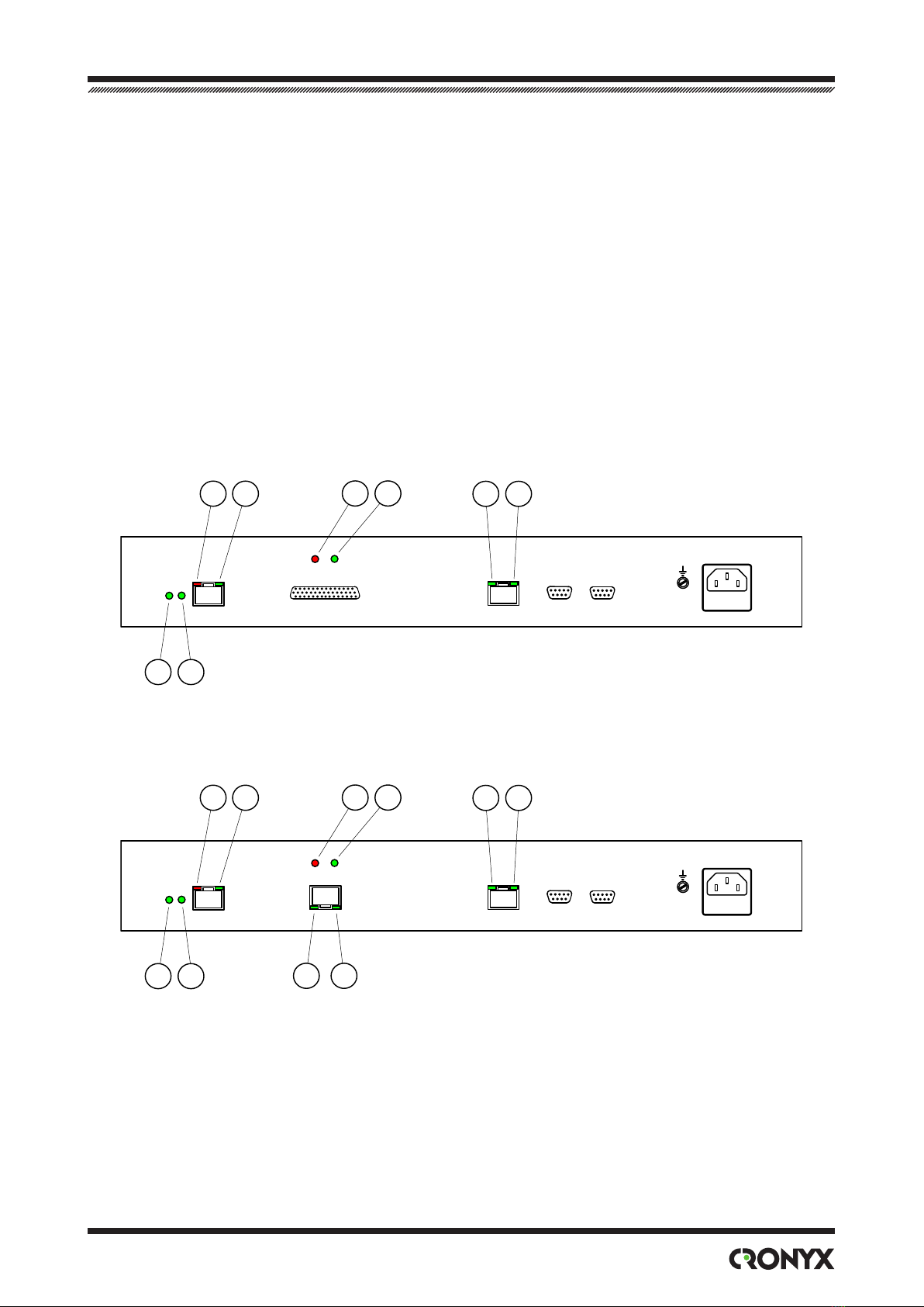
All connectors are located on the front panel of the modem.
Figure below shows the front panel of the device ordered with Ethernet V.35 / RS-530 /
RS-232 / X.21 digital port and identies connector locations:
Alarm Port
Console Port
E1 Link
Power
GND
SNMP Port
PWR TST
PORT 0
LINK 0 SNMP CONSOLE ALARM
Digital Port
12 Modem-Converter E1-L/S
© 2006 Cronyx
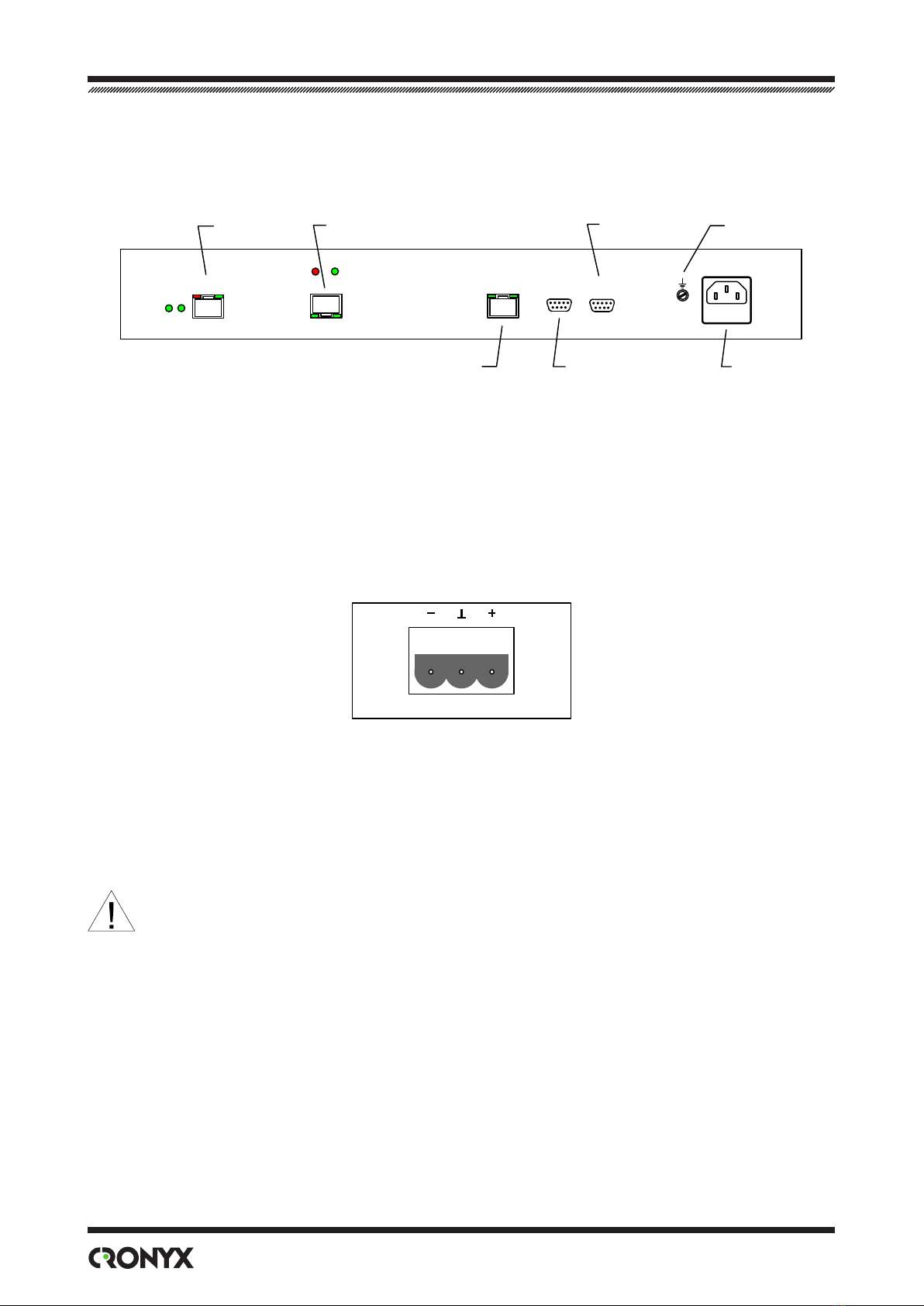
Figure below shows the front panel of the device ordered with Ethernet 10/100Base-T
digital port and identies connector locations:
Alarm Port
Console Port
E1 Link
Power
GND
SNMP Port
PWR TST
PORT 0
LINK 0 SNMP CONSOLE ALARM
Ethernet 10/100Base-T Port
Power Connection
AC power (for the «-AC» version) is supplied to the device through a standard AC power
connector (IEC 320 C14). e power cable is supplied with the device.
e DC power connector (for the «-DC» version) is shown below (view from the front
of the device):
e 3-screw removable terminal block is supplied with the device.
Ground Terminal
An M4 grounding screw is located on front panel of the device.
Before powering the device on and before connecting other cables, the mo-
dem unit must be properly grounded.

© 2006 Cronyx
13
Section 2. Installation
E1 Link Connector
An RJ-48 socket is provided for the E1 link cable connection:
Ethernet 10/100Base-T Port and SNMP Port Connectors
An RJ-45 sockets are provided for connection cables to Ethernet 10/100Base-T port and
SNMP port:
Use straight cable to connect the device to Ethernet hub.
14 Modem-Converter E1-L/S
© 2006 Cronyx
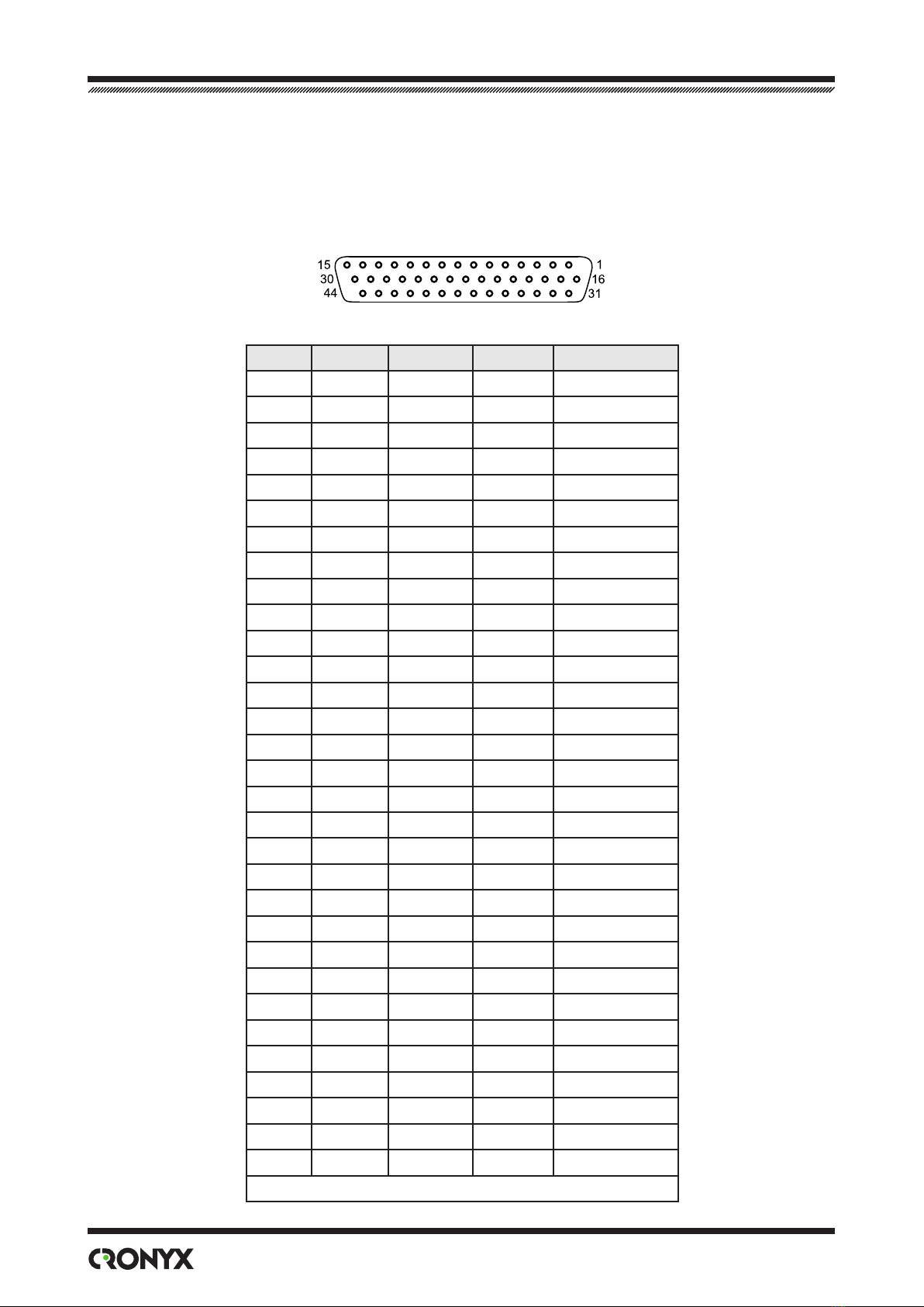
Digital Port (V.35 / RS-530 / RS-232 / X.21) Connector
e HDB44 (female) connector is provided for connection cable to the multistandard
(«-M» version) digital interface port:
Pin. V.35 RS-530 RS-232 X.21
10 TXD-a TXD-a TXD Transmit(A)
25 TXD-b TXD-b — Transmit(B)
8 RXD-a RXD-a RXD Receive(A)
9 RXD-b RXD-b — Receive(B)
6 ETC-a ETC-a ETC ETC(A)
7 ETC-b ETC-b — ETC(B)
2 TXC-a TXC-a TXC SigTiming(A)
3 TXC-b TXC-b — SigTiming(B)
5 RXC-a RXC-a RXC —
4 RXC-b RXC-b — —
17 ERC-a ERC-a ERC —
18 ERC-b ERC-b — —
14 RTS RTS-a RTS Control(A)
29 — RTS-b — Control(B)
11 DTR DTR-a DTR —
26 — DTR-b — —
13 DSR DSR-a DSR —
28 — DSR-b — —
15 CTS CTS-a CTS —
30 — CTS-b — —
12 CD CD-a CD Indication(A)
27 — CD-b — Indication(B)
1,16 GND GND GND GND
31 SEL-0* SEL-0* SEL-0* SEL-0
33 SEL-1 SEL-1* SEL-1 SEL-1*
35 SEL-2 SEL-2 SEL-2* SEL-2
37 SEL-3 SEL-3* SEL-3* SEL-3*
39 SEL-4* SEL-4 SEL-4 SEL-4
41 SEL-5* SEL-5 SEL-5 SEL-5
43 SEL-6* SEL-6 SEL-6 SEL-6
32 DCE DCE DCE DCE
* - Connect to GND

© 2006 Cronyx
15
Section 2. Installation
Digital Port (V.35) Connector
e M-34 (female) connector is provided for connection cable to the V.35 («-V» version)
digital interface port:
Pin Signal Direction
P TD-a Input
S TD-b Input
R RD-a Output
T RD-b Output
U ET-a Input
W ET-b Input
Y TC-a Output
AA TC-b Output
BB ERC-a Input
Z ERC-b Input
V RC-a Output
X RC-b Output
C RTS Input
H DTR Input
E DSR Output
D CTS Output
F DCD Output
A CGND —
B SGND —
Console Port Connector
Device operation may be controlled from the ASCII terminal (the console). DB-9 (fe-
male) connector is used to connect the console. Console port has a standard RS-232
DCE interface and should be used in asynchronous operating mode, 9600 bps rate, 8 bit
per character, 1 stop bit, no parity. Use straight cable to connect to the computer COM
port.
An RTS signal (for ow control) from the console terminal is required for
proper operation.
16 Modem-Converter E1-L/S
© 2006 Cronyx
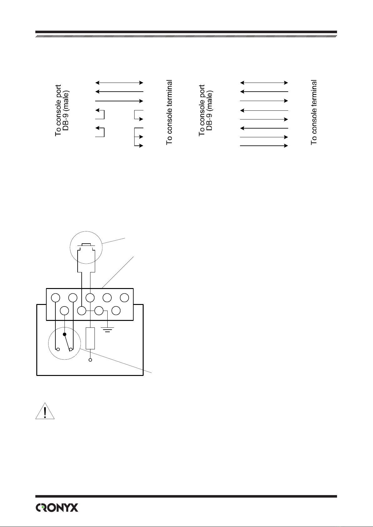
e following cable wiring schemes are recommended:
Cable without modem control
GND 5
TXD 3
RXD 2
RTS 7
CTS 8
DTR 4
CD 1
GND
TXD
RXD
RTS
CTS
DTR
DSR
CD
GND 5
TXD 3
RXD 2
RTS 7
CTS 8
DTR 4
DSR 6
CD 1
GND
TXD
RXD
RTS
CTS
DTR
DSR
CD
Cable with modem control
Use straight cable to connect to the COM port of the computer.
Alarm Port Connector
A DB-9 (female) connector is used for alarm port connection:
Pin allocation:
5 – open in no alarm state, closed to middle relay contact (9)
on alarm
4 – closed to middle relay contact (9) in no alarm state, open
on alarm
3 – to external input sensor
9 – middle relay contact
7, 8 – GND
1, 2, 6 – reserved (must be leaved unconnected)
Alarm relay
(shown in no alarm state)
External input sensor
54321
87
96
+5 VDC
Internal device circuits
Pin layout shown from outside of the device
e external input sensor connected to the modem must be isolated from other
electrical circuits. Failure to comply with this requirement may lead to modem
breakdown.
© 2006 Cronyx
17
Chapter 3. Operation
Chapter 3. Operation
3.1. Front Panel Indicators
e indicators displaying the unit status are located on the front panel. e list of indi-
cators and their purpose are shown in the table. e reference numbers on the gures
correspond to the numbers in the table.
Figure below shows the front panel of the device ordered with V.35 / RS-530 / RS-232 /
X.21 digital port and identies indicator locations:
PWR TST
PORT 0
LINK 0 SNMP CONSOLE ALARM
123456
78
Figure below shows the front panel of the device ordered with Ethernet 10/100Base-T
digital port and identies indicator locations:
PWR TST
PORT 0
LINK 0 SNMP CONSOLE ALARM
123456
910
78

18 Modem-Converter E1-L/S
© 2006 Cronyx
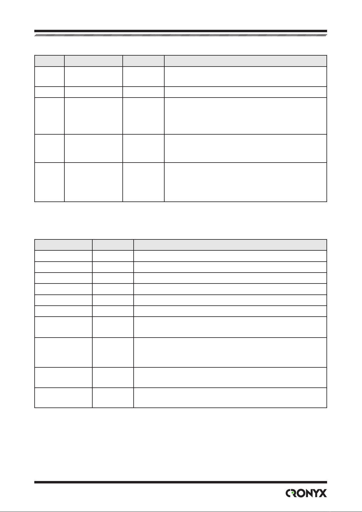
No. Indicator Color Function/Light State
1LINK LOS Red E1 link errors:
• ON if E1 link input carrier is lost or if
there is no frame or multiframe synchroni-
zation;
• ON when the AIS signal is being received
at the input of the E1 link;
• ashes in case of HDB3 coding errors of
the E1 link;
• ashes if there is no frame synchroni-
zation at the remote device (bit A of the
timeslot 0).
2LINK STATE Green E1 link operating mode:
• ON on normal operation;
• ashes if local loopback is enabled;
• ashes in double ashes if remote loop-
back is enabled.
3PORT LOS Red V
.35 / RS-530 / RS-232 / X.21 digital port er-
ror (ON or ashes):
• RTS line is o;
• ETC line is o (if external synchroniza-
tion is selected)
• FIFO data buer error;
• coding error (when operating not at
maximum data rate).
Ethernet 10/100Base-T port error:
• ON if cable is not connected to the
10/100Base-T Ethernet port;
• ashes if packet with wrong checksum
received or packet is lost because of insuf-
cient throughput of the channel.
4PORT STATE Green V
.35 / RS-530 / RS-232 / X.21 digital port
state:
• ON if RTS line is on;
• ashes if digital loopback is enabled.
Ethernet 10/100Base-T port state:
• ON if Ethernet cable is connected;
• OFF if Ethernet cable is not connected.
5SNMP EACT Green Flashes during Ethernet 10Base-T data trans-
mission via the SNMP port.
© 2006 Cronyx
19
Chapter 3. Operation
No. Indicator Color Function/Light State
6SNMP ELINK Green ON if Ethernet 10Base-T cable is connected to
the SNMP port.
7PWR Green On when power is switched on.
8TST Green/ red Test mode indicator. ON if BER tester is ena-
bled:
• lights green if no errors detected;
• lights red on errors.
9ETH FAST Green Ethernet 10/100Base-T port mode:
• ON in the 100Base-T mode;
• OFF in 10Base-T mode.
10 ETH LINK Green Ethernet 10/100Base-T port state:
• ON if cable is connected;
• ashes during Ethernet data transmis-
sion is in progress.
During the normal operation, the indicators must be in the following states:
Indicator Color Light State at Normal Operating Condition
PWR Green ON
TST Green/red OFF
LINK LOS Red O
LINK STATE Green ON
PORT LOS Red OFF
PORT STATE Green ON
ETH FAST Green ON in 100 Mbps mode of the Ethernet 10/100Base-T
port.
ETH LINK Green ON if cable is connected to the Ethernet
10/100Base-T port; ashes during Ethernet data trans-
mission is in progress.
SNMP EACT Green Flashes during Ethernet 10Base-T data transmission via
the SNMP port.
SNMP ELINK Green ON if Ethernet 10Base-T cable is connected to
the SNMP port.

20 Modem-Converter E1-L/S
© 2006 Cronyx
3.2. Synchronization Modes
For E1 channel, the single clock source is used as a rule. e source of clock signal may
be an internal oscillator of any E1 modem or external clock signal of any DTE. Examples
are shown in gures below.
TXC
RXC
RXC
TXC
CLK
TXC
ETC RXC
TXC
CLK
RXC
Table of contents


