SERIAL CONVERTER / ETHERNET
TCP-485
Ver.04
WARNING
THROUGH CONTINUOUS DEVELOPMENT, FULL GAUGE CONTROLS RESERVES THE RIGHT TO
CHANGE THE INFORMATION IN THIS MANUAL AT ANY TIME, WITHOUT PRIOR NOTICE.
Operating temperature 0 to 50ºC / 32 to 122ºF
Operating humidity 10 to 90% UR (without condensation)
32
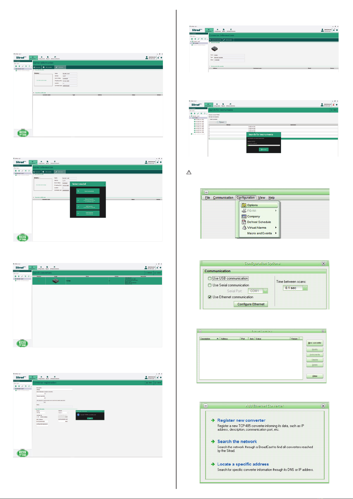
5. INSTALLATION AND OPERATION (DHCP MODE - DEFAULT
CONFIGURATION)
Have this manual in your hands
using the FG Finder application.
Converter power External power supply 5.1 Vdc / 2A
Number of instruments supported per
converter in the RS-485 network
Ethernet speed 10Mbps
Product dimensions 91,0 x 91,1 x 37,1 mm (WxHxP)
Connections
Power supply provided with the converter Input - 100-240Vac (50/60Hz)
Output -5.1Vdc / 2A
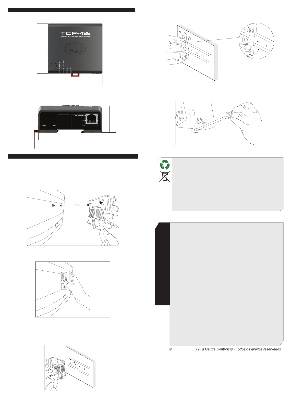
1. DESCRIPTION
2. APPLICATIONS
3. TECHNICAL SPECIFICATIONS
The Serial/ Ethernet converter TCP-485 allows interconnecting Full Gauge controllers with the
supervisory software Sitrad through an Ethernet data network using the TCP/IP communication standard.
Currently, many companies have the Ethernet cabling ready in their facilities. With the TCP-485
converter, you can use the cabling already installed, making it unnecessary to create a new cabling for the
RS-485 network of the controllers.
The system consists of an Ethernet/RS-485 converter connected to the Ethernet network (be it by internet,
intranet, or directly to the computer) and Sitrad, which makes a direct TCP/IP connection to the Ethernet/
RS-485 converter, allowing communication with the controllers connected to it.
The converter transforms the RS-485 electrical standard used by the controllers into the TCP/IP
communications protocol used in the interconnection of computer networks.
- Facilities without conditions to install new cabling, and with an Ethernet structure already in place.
- Centralize data collection from multiple remote locations onto one server without needing a computer
dedicated to each remote location.
NOTE: The TCP-485 converter is designed to work specifically with Full Gauge Controls instruments.
Connect interface terminals A,B and with the respective A,B and terminals on connecting blocks and
instruments;
With the TCP-485 powered on, use an Ethernet cable to connect it to a router (switch) in the RJ-45
connectors according to the picture.
-Connection type RJ-45 for connections to a PC using
the twisted-pair cable supplied along with the converter;
- One insulated RS-485 port to connect up to 32
instruments without the need of termination;
- Direct 80 cm Ethernet cable ( no crossover) supplied
along with the converted.
4. WIRING DIAGRAM
LED Power - Power
indication LED
R S - 4 8 5 n e t w o r k
transmission indication LED
R S - 4 8 5 n e t w o r k
reception indication LED
IMPORTANT INFORMATION:
If the ‘’LAN’’ LED indicator in the RJ-45 connector does not light up upon connecting
the TCP-485 converter directly to the network adapter of the computer, you may
possibly need to use a crossover cable ( not supplied by Full Gauge) or connect the
computer and the converter via a HUB or a Switch.
STANDARD OPERATING MODE:
The factory’s default operation of TCP-485 is DHCP Mode. See item 7 - Restoring the
default settings of the converter/ Changing IP Mode to switch the operation Mode.
IMPORTANT:
For a correct and robust installation of the RS-485 network, see item 9 -
Interconnecting the controllers and TCP-485.
!
!
!
Supervisory
system
Serial Ethernet
communication
RS
485
L E D S t a t u s -
Connect ion sta tus
indication LED
Reset key
Converter power
TCP-485
RJ45 Router
Controller
Source
RS-485
MT-530 super
TCP485V04-02T-16955
Communication network
with RS-485 instruments
MT-530 super
BEFORE THE INSTALLATION OF THE CONVERTER, WE RECOMMEND READING THE
INSTRUCTION MANUAL IN FULL TO PREVENT POSSIBLE DAMAGE TO THE PRODUCT.
PRODUCT INSTALLATION PRECAUTIONS:
Before performing any procedure on this instrument, disconnect it from the power grid;
Ensure that it has adequate ventilation, avoiding installation on control panels containing devices that
could cause it to operate outside its specified temperature range;
Install the product away from sources that may generate eletromagnetic disturbances, such as :
motors, contactors, relays, electrovalves, etc.;
AUTHORIZED SERVICES:
The installation and maintenance of the product must be performed only by qualified personnel;
ACCESSORIES
Use only Full Gauge Controls original accessories.
If you have any questions, please contact our technical support