Crookwood VU User manual
Crookwood VU Meter User guide
Everything you need to know about your VU meter
> Contents
> Overview ........................................................................................................................................................................................................................................... 2
Warning! ......................................................................................................................................................................................................................................... 2
> How to get the meters up and running ....................................................................................................................................................................................... 2
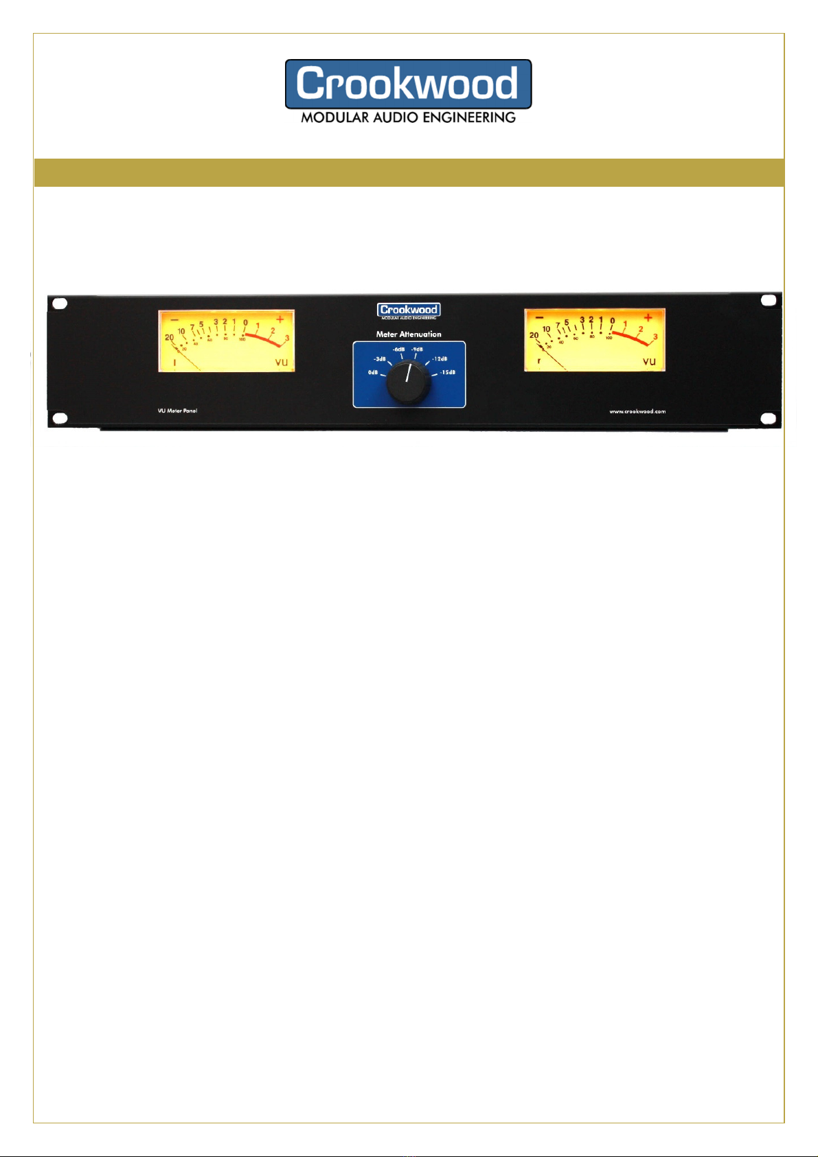
> Panel pictures ................................................................................................................................................................................................................................... 3
Front Panel View.................................................................................................................................................................................................................... 3
Rear Panel View ..................................................................................................................................................................................................................... 3
> Installation .........................................................................................................................................................................................................................................
Audio Connections .......................................................................................................................................................................................................................
Too tight? .......................................................................................................................................................................................................................................
Where should I connect my VU? ..............................................................................................................................................................................................
> Calibration ......................................................................................................................................................................................................................................... 5
Basic Calibration ........................................................................................................................................................................................................................... 5
Mechanical Calibration ................................................................................................................................................................................................................ 5
> Using the VUs .................................................................................................................................................................................................................................. 7
Front Panel Attenuator ............................................................................................................................................................................................................... 7
Different Levels measurement systems................................................................................................................................................................................... 7
Digital Levels ................................................................................................................................................................................................................................. 7
Analogue Levels ............................................................................................................................................................................................................................ 8
Peaks and Averages ..................................................................................................................................................................................................................... 8
LuFs and VUs................................................................................................................................................................................................................................. 8
Using the VU to calibrate other kit ........................................................................................................................................................................................... 9
> Problems? Questions? .................................................................................................................................................................................................................. 10

New Product Release information for dealers
continued…
> Overview
The Crookwood
CrookwoodCrookwood
Crookwood VU meters are dual channel precision Sifam VU meters, and mounted on
2U panel with LED backlights and an acti e meter input attenuator.
They ha e these features:
•2U 19” for easy mounting, with optional wooden surround for desktop applications
•Unique built in precision multi position attenuator, so the VU units will work properly
with any studio le el. Without this attenuator other VU meters can’t be used fully with
modern digital le els
•XLR inputs on rear of meter
•Large, proper Sifam VU mechanical meters, not cheap knock offs, they perform to the
VU spec almost perfectly
•LED meter backlighting for ery long life, with gel film for a gentle yellow colour
•Electronic balanced high impedance inputs allow connection to any type of de ice,
balanced or not, without any loading issues.
•Open rear for easy calibration and trimming
•Only 8cm deep, so it can fit in any space
•Supplied with 12V DC plug in power supply, 1m lead length, uni ersal mains fittings
•Modular construction, easy to upgrade or repair
•There are trims a ailable for the electrical and mechanical calibration of the meters.
Warning!
These meters are mechanically based. They ha e sensiti e mo ing parts and will break if
dropped or knocked hea ily. Just take care, and they will last a ery long time.
> How to get the meters up and running
After deli ery, please check that there is no ob ious mechanical damage, then follow
this procedure:
1. Install the meters into your studio. See the installation notes in this manual
2. Calibrate the meters. The meters are pre-calibrated, but you need to re-calibrate them
after shipping, as the mechanical mo ement will ha e altered. See the calibration notes
in this manual
3. Use the meters! There are notes on using the attenuator and le els in the user section
of this manual.

New Product Release information for dealers
continued…
> Panel pictures
Front Panel View
Rear Panel View

New Product Release information for dealers
continued…
> Installation
The meters are easy to install. The 2RU version just gets bolted into a frame, or it will
come with an optional desktop wooden pod, like this:
The 2RU meter needs 0mm of depth behind the panel.
Audio onnections
At the rear of each panel by the attenuator are 2 XLR sockets for the audio inputs.
Looking from the rear, the left socket is for the left meter, and the right socket is for
the right meter.
Allow 100mm (4”) for putting the matching XLRs into the rear of the meter panels. This
means allowing a clearance of 125mm (5”) from the front of each panel to the rear.
Too tight?
Where the meter depth doesn’t allow it, you can do the following to reduce the depth to
40mm (1.75”)
•Fold over the ¼” spade connectors on each of the meters until they are parallel with
the front panel.
•Use right angle XLE connectors
Where should I connect my VU?
The best place is across a meter output on your monitor controller or console. That way
you can select what you want to meter, and meter what you’re hearing.
Failing this, try to connect it across a monitor DAC, or on the inputs to a ADC after an
analogue chain. The high impedance inputs make this easy to do, but you’ll need to make
up a passive mult cable to split the signal to the meters and the normal destination.

New Product Release information for dealers
continued…
> alibration
There are two calibration trims: an electrical one which adjusts the gain of the meter, and a
mechanical one, which alters the offset of the meter needle from rest.
Usually, you’ll only have to alter the electrical one, but there are instances when you’ll
need to adjust both.
Basic alibration
Use the electric trim pots for this. They are located on the rear, under the XL socket. As
viewed from the rear, the left hand pot trims the L meter, and the right hand pot trims the
meter.
Viewed from the front, they are obviously reversed ( left pot trims meter, right pot trims
L meter).
The pots have about 2dB of movement on them, they don’t alter the meter dynamics, and
will trim the meter for all attenuations. If the required trim is greater than this, trim them
for maximum, then trim mechanically (see below).
Follow this procedure:
•Ideally trim for 0VU at the 0dB attenuation setting. This will give you the most
confidence going forwards. efer to the table on page 4 for the appropriate level
in dBu.
•If you can’t easily do this, trim at any attenuator setting that make sense. It will
still work.
•Send out a 1KHz sine wave from your DAW, making sure nothing is clipping.
•Adjust the electric trim until the meter needle is exactly over the 0VU marking.
Mechanical alibration
On the back of each meter is a black screw type trimmer. This adjusts the position of the
meter needle relative to the signal level. Normally you shouldn’t have to touch this, but
occasionally you won’t be able to calibrate the meter without it. Why? Well it could be
because of one of these reasons:
•The mechanical mechanism has been shocked, and the needle displaced
•Your analogue meter outputs have relatively high impedance, so the meter is
reading low.
•There is loss elsewhere in the system, which you have to make up on the meters.
Whatever it is, you can adjust the mechanical stops as well. When you do this, you will
notice that the VU needle will sit at or slightly above the -20VU indicator even when there
is no signal present. It’s a trade off you’ll have to make, but again in practice means
nothing because you’re interested in the moving music levels, not static test levels.

New Product Release information for dealers
continued…
To trim the meter:
•First trim it as best you can with the electrical trimmers
•Then adjust the mechanical trim until the meter is calibrated. Note that there is a bit of
hysteresis with the mechanical trimmer, so after trimming, turn the signal off and on to
make sure it’s still calibrated.

New Product Release information for dealers
continued…
> Using the VUs
This seems like a silly section, it’s obvious isn’t it? Well yes, but here’s some useful facts.
Front Panel Attenuator
This allows you to set the range of the meters, so that the needles don’t ram up against
the stops if the level is too loud. They are adjustable in 3d steps, so you can choose the
best range for your application.
Here’s a useful table showing you what the steps and the levels actually mean.
Attenuator
Setting
0VU
+3VU
0
+4d u
+7d u
-
3
+7d u
+10d u
-
6
+10d u
+13d u
-
9
+13d u
+16d u
-
12
+16d u
+19d u
-
15
+19d u
+22d u
Different Levels measurement systems
d u is an absolute reference value of level, independent of impedances. For reference,
your digital gear will be calibrated in d Fs, where 0d Fs is the maximum output level that
the converter can output (or accept on its inputs).
Ready for some maths?
Typically you’ll set up your levels so that at say -14d Fs you’ll get 0VU. This means that
your 0d Fs level is +18d u (14d of headroom in digital till 0d Fs, plus 0VU ( which is
+4d u) = 18d u)!
What does this mean for you? Well your operating levels affect how loud things are and
also how some pieces of equipment respond to them.
Digital Levels
All digital levels are absolute. The maximum they can ever go is 0d Fs. However your
converters will map this into an analogue world, where the absolute maximum signal is
typically +27d u for balanced gear, or +21d u for unbalanced gear. The calibration above
of 0d Fs = +18d u, means that you will never clip any of your analogue gear. However,

New Product Release information for dealers
continued…
once you’re in the analogue domain, you’ve got an extra 9dB of possible headroom to play
with, before you have to attenuate it back into the digital domain for storage again. This is
perhaps why analogue summing boxes got popular.
You can use this headroom to Q and compress signals without clipping, or you can
selectively clip signals for effect. At the end of the chain you’ll have to attenuate the level
back to below 0dBFs to avoid digital clipping however. Or not if you want to clip digitally
for effect!
Some older pieces of equipment will sound different at higher levels, and some people
then change their operating level to be lower than this, say 0dBFs= 12dBu. Their rooms
will sound quieter however, unless they add gain into the monitor chain.
The adjustable attenuator on our meters allows you to make sure you can see what is
going on, at any point.
Analogue Levels
In the olden days, music was stored on analogue tape machines. These had a maximum
storage level of about +10dBu, so with average music a VU meter without an attenuator
was about perfect for indicating levels.
Peaks and Averages
A VU meter is an averaging type meter: it shows the average level of the music. A digital
peak meter – like the one on your DAW, however shows the peak level of the music.
Another type of meter, a true peak meter shows where the signal would peak at, if it didn’t
clip at 0dBFs You can play two different pieces of music into a peak meter and they will
indicate that they are about the same level. However when you play them, one can be
much, much louder. A VU will show you this difference.
LuFs and VUs
The modern way to measure loudness is with LuFs –an average loudness level. Modern
meters have great LuFs and true peak displays, and are really useful to see what might
happen to your music when it hits a streaming service.
But…
Music is a living thing, if you spend your time agonising over LuFs and staring at a screen,
the chances are the music will suffer. It’s much better to manipulate it using your ears,
and glance at our VU meter to get a sense whether or not you’re going too loud. A classic
case of less is more!
We’ve got a full article about this here: https://crookwood.com/blog/the-beauty-of-vu-
meters/

New Product Release information for dealers
continued…
Using the VU to calibrate other kit
If you’ve calibrated your VU, you can use it to calibrate other pieces of equipment in the
studio. But here’s a few notes:
•Only use sine waves for calibratin , and make sure nothin ’s clippin . You’ll et very
different levels with non-sine or clipped waveforms, even if a di ital peak meter says
they are the same value.
•Despite our best efforts, there will be about 0.1dB error as you move between the
different attenuations. This shouldn’t matter to real life, so please don’t et hun up
about sli ht differences in steady state sine wave levels between attenuations. It’s
ood enou h for 99% of all the calibration you’ll have to do.
•The VU is very accurate relatively to about 0.05dB chan es in level (a needle thickness
at 0VU). So on the same attenuation settin , you can use it to compare left and ri ht
levels accurately. However these 0.05dB levels are very fine, and in practise 0.25dB
matchin is more than ood enou h for everyday use, even masterin only really
require +/- 0.1dB. If you try and re ularly calibrate finer than this you’ll o quite mad,
as your eyes won’t be able to repeatedly resolve the differences on the meter, and
analo ue ear drifts, especially compressors!
•Look strai ht at the meter when you calibrate, not to the side. You’ll lose 0.25dB easily
if you do.
•The VU is not accurate at the bottom end of its ran e. Do not try to calibrate
stuff at -20VU!
This may seem a bit pedantic: the VU can be used successfully to calibrate other
equipment, but day to day, you want to use it with music not sine waves. This is where
you’ll see its true value.

New Product Release information for dealers
continued…
> Problems? Questions?
At any point, please feel free to call us for advice. Our details are:
Crookwood
239, East Grafton
Marl orough
Wiltshire, SN8 3DF
England
Tel: +44 (0) 1672 811 649
Fax: +44 (0)1672 811 650
Email: sales@crookwood.com
We : www.crookwood.com
Thank you again for uying this meter from us.
Table of contents
Popular Measuring Instrument manuals by other brands

Shimpo Instruments
Shimpo Instruments PT-110 Operation manuals

Process Sensors
Process Sensors MCT466-QC User guide manual

London Electronics
London Electronics Fusion-L 6 digit Connection details, scaling and general information

Simex
Simex STI-638 user manual

drM
drM SPC100 quick start guide

Rotronic
Rotronic CRP5 SERIES manual


HACH LANGE
HACH LANGE Pocket Colorimeter II user manual

Elster
Elster ALPHA A1800 Technical manual

Air TEc
Air TEc Expert CYPRES 2 user guide

Fukuda
Fukuda CardiMax Series Service manual

Elgato
Elgato Eve Energy quick start guide

PCB Piezotronics
PCB Piezotronics IMI SENSORS HT625B01 Installation and operating manual