manuals.online logo
Brands
  1. Home
  2. •
  3. Brands
  4. •
  5. Elster
  6. •
  7. Measuring Instrument
  8. •
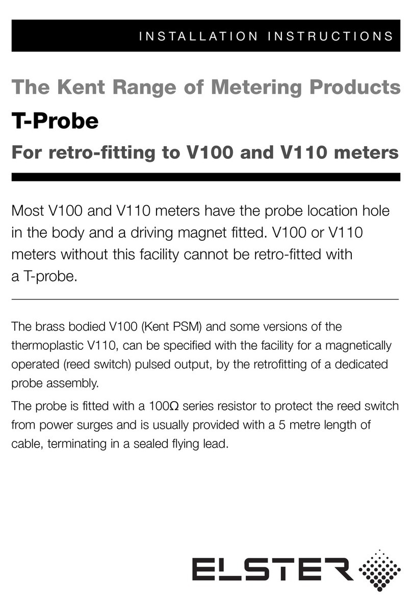
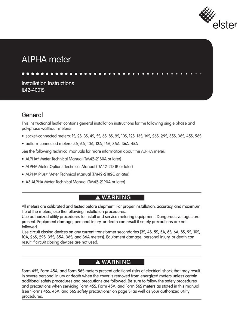
  9. Elster ALPHA A1800 User manual

Elster ALPHA A1800 User manual

A1800 ALPHA Meter
Technical Manual
Rev.02
10-2011
www.izmerenie.ru
Technical manual iContents
Contents
1 Introduction . . . . . . . . . . . . . . . . . . . . . . . . . . . . . . . . . . . . . . . 1-1
A1800 ALPHA meter . . . . . . . . . . . . . . . . . . . . . . . . . . . . . . 1-1
Standards Compliance . . . . . . . . . . . . . . . . . . . . . . . . . . 1-2
IEC . . . . . . . . . . . . . . . . . . . . . . . . . . . . . . . . . . . . . . . . 1-2
IEEE/ANSI . . . . . . . . . . . . . . . . . . . . . . . . . . . . . . . . . 1-2
DIN . . . . . . . . . . . . . . . . . . . . . . . . . . . . . . . . . . . . . . . 1-2
Benefits . . . . . . . . . . . . . . . . . . . . . . . . . . . . . . . . . . . . . . 1-3
Reliability . . . . . . . . . . . . . . . . . . . . . . . . . . . . . . . . . . 1-3
Maintainability . . . . . . . . . . . . . . . . . . . . . . . . . . . . . . . 1-3
ANSI standard communication open protocol . . . . . . 1-4
Adaptability . . . . . . . . . . . . . . . . . . . . . . . . . . . . . . . . . 1-4
Economy . . . . . . . . . . . . . . . . . . . . . . . . . . . . . . . . . . . 1-4
Security . . . . . . . . . . . . . . . . . . . . . . . . . . . . . . . . . . . . 1-4
Accuracy . . . . . . . . . . . . . . . . . . . . . . . . . . . . . . . . . . . 1-4
Meter types . . . . . . . . . . . . . . . . . . . . . . . . . . . . . . . . . . . . . . 1-5
Meter series . . . . . . . . . . . . . . . . . . . . . . . . . . . . . . . . . . . 1-6
2 Product description . . . . . . . . . . . . . . . . . . . . . . . . . . . . . . . . . 2-1
Physical description . . . . . . . . . . . . . . . . . . . . . . . . . . . . . . . . 2-1
Optical port . . . . . . . . . . . . . . . . . . . . . . . . . . . . . . . . . 2-3
LCD . . . . . . . . . . . . . . . . . . . . . . . . . . . . . . . . . . . . . . . 2-3
Nameplate . . . . . . . . . . . . . . . . . . . . . . . . . . . . . . . . . . 2-3
Utility information card . . . . . . . . . . . . . . . . . . . . . . . . 2-4
Communications . . . . . . . . . . . . . . . . . . . . . . . . . . . . . 2-4
Battery . . . . . . . . . . . . . . . . . . . . . . . . . . . . . . . . . . . . . 2-5
Cover tamper detection switches . . . . . . . . . . . . . . . . . 2-5
Terminal configurations . . . . . . . . . . . . . . . . . . . . . . . . 2-6
Communication protocols . . . . . . . . . . . . . . . . . . . . . . . . . . . 2-6
System architecture . . . . . . . . . . . . . . . . . . . . . . . . . . . . . . . . 2-6
General theory of operation . . . . . . . . . . . . . . . . . . . . . . . . . . 2-7
Power supply . . . . . . . . . . . . . . . . . . . . . . . . . . . . . . . . . . 2-7
Main power supply . . . . . . . . . . . . . . . . . . . . . . . . . . . 2-7
Auxiliary power supply . . . . . . . . . . . . . . . . . . . . . . . . 2-7
Current and voltage sensing . . . . . . . . . . . . . . . . . . . . . . 2-7
Meter engine . . . . . . . . . . . . . . . . . . . . . . . . . . . . . . . . . . 2-8
Microcontroller . . . . . . . . . . . . . . . . . . . . . . . . . . . . . . . . 2-8
EEPROM . . . . . . . . . . . . . . . . . . . . . . . . . . . . . . . . . . . . 2-8
Billing data . . . . . . . . . . . . . . . . . . . . . . . . . . . . . . . . . . . . . . 2-9
Metered energy and demand quantities . . . . . . . . . . . . . 2-9
Average power factor . . . . . . . . . . . . . . . . . . . . . . . . . . . 2-9
Demand calculations . . . . . . . . . . . . . . . . . . . . . . . . . . . . 2-9
Rolling interval . . . . . . . . . . . . . . . . . . . . . . . . . . . . . 2-10
Block interval . . . . . . . . . . . . . . . . . . . . . . . . . . . . . . . 2-10
Thermal time constant . . . . . . . . . . . . . . . . . . . . . . . . 2-11
Maximum demand . . . . . . . . . . . . . . . . . . . . . . . . . . . . 2-11
Cumulative maximum demand . . . . . . . . . . . . . . . . . . . 2-11
Continuous cumulative maximum demand . . . . . . . . . 2-11
Coincident demand or power factor . . . . . . . . . . . . . . . 2-12
Contents
Technical manual
Technical manual ii Contents
Demand forgiveness . . . . . . . . . . . . . . . . . . . . . . . . . . . 2-12
Primary and secondary metering . . . . . . . . . . . . . . . . . 2-12
TOU data . . . . . . . . . . . . . . . . . . . . . . . . . . . . . . . . . . . . 2-12
Power failure data . . . . . . . . . . . . . . . . . . . . . . . . . . . . . 2-13
Logs and data sets . . . . . . . . . . . . . . . . . . . . . . . . . . . . . . . . 2-13
Event log . . . . . . . . . . . . . . . . . . . . . . . . . . . . . . . . . . . . 2-14
History log . . . . . . . . . . . . . . . . . . . . . . . . . . . . . . . . . . 2-14
Self reads . . . . . . . . . . . . . . . . . . . . . . . . . . . . . . . . . . . . 2-14
Load profiling . . . . . . . . . . . . . . . . . . . . . . . . . . . . . . . . 2-15
Load profiling pulse divisor . . . . . . . . . . . . . . . . . . . . 2-15
Instrumentation profiling . . . . . . . . . . . . . . . . . . . . . . . 2-16
TRueQ Log . . . . . . . . . . . . . . . . . . . . . . . . . . . . . . . . . . 2-17
Voltage sag log . . . . . . . . . . . . . . . . . . . . . . . . . . . . . . . 2-17
User-defined tables . . . . . . . . . . . . . . . . . . . . . . . . . . . . 2-17
Physical dimensions and mass . . . . . . . . . . . . . . . . . . . . . . 2-18
3 Operating instructions . . . . . . . . . . . . . . . . . . . . . . . . . . . . . . . 3-1
Indicators and controls . . . . . . . . . . . . . . . . . . . . . . . . . . . . . 3-1
LCD . . . . . . . . . . . . . . . . . . . . . . . . . . . . . . . . . . . . . . . . . 3-1
Quantity identifier . . . . . . . . . . . . . . . . . . . . . . . . . . . . 3-2
Display quantity . . . . . . . . . . . . . . . . . . . . . . . . . . . . . . 3-2
Phase indicators . . . . . . . . . . . . . . . . . . . . . . . . . . . . . . 3-2
Energy direction indicators . . . . . . . . . . . . . . . . . . . . . 3-2
Power/energy units identifier . . . . . . . . . . . . . . . . . . . . 3-3
Alternate display indicator . . . . . . . . . . . . . . . . . . . . . . 3-3
Error indicator . . . . . . . . . . . . . . . . . . . . . . . . . . . . . . . 3-3
Low battery indicator . . . . . . . . . . . . . . . . . . . . . . . . . . 3-3
Active COM port indicator . . . . . . . . . . . . . . . . . . . . . 3-3
Display indicators . . . . . . . . . . . . . . . . . . . . . . . . . . . . 3-3
Push buttons . . . . . . . . . . . . . . . . . . . . . . . . . . . . . . . . . . 3-4
RESET button . . . . . . . . . . . . . . . . . . . . . . . . . . . . . . . 3-4
* button . . . . . . . . . . . . . . . . . . . . . . . . . . . . . . . . . . . 3-5
Using the backlight . . . . . . . . . . . . . . . . . . . . . . . . . . . 3-6
Operating modes . . . . . . . . . . . . . . . . . . . . . . . . . . . . . . . . . . 3-7
Normal mode . . . . . . . . . . . . . . . . . . . . . . . . . . . . . . . . . 3-7
Alternate mode . . . . . . . . . . . . . . . . . . . . . . . . . . . . . . . . 3-8
Test mode . . . . . . . . . . . . . . . . . . . . . . . . . . . . . . . . . . . . 3-8
Demand reset . . . . . . . . . . . . . . . . . . . . . . . . . . . . . . . . . . . . . 3-9
Demand reset lockout . . . . . . . . . . . . . . . . . . . . . . . . . . 3-10
Demand reset data area . . . . . . . . . . . . . . . . . . . . . . . . . 3-10
4 Meter tools . . . . . . . . . . . . . . . . . . . . . . . . . . . . . . . . . . . . . . . . 4-1
System instrumentation . . . . . . . . . . . . . . . . . . . . . . . . . . . . . 4-1
System service tests . . . . . . . . . . . . . . . . . . . . . . . . . . . . . . . . 4-5
Service voltage test . . . . . . . . . . . . . . . . . . . . . . . . . . . . . 4-5
System service locking . . . . . . . . . . . . . . . . . . . . . . . . 4-5
Initiating service voltage tests . . . . . . . . . . . . . . . . . . . 4-7
Restarting the service voltage test in diagnostic mode 4-9
Service current test . . . . . . . . . . . . . . . . . . . . . . . . . . . . . 4-9
Initiating the service current test . . . . . . . . . . . . . . . . 4-10
System service error codes . . . . . . . . . . . . . . . . . . . . . . 4-10
TRueQ monitoring . . . . . . . . . . . . . . . . . . . . . . . . . . . . . . . 4-12
TRueQ timing . . . . . . . . . . . . . . . . . . . . . . . . . . . . . . . . 4-12
TRueQ display items . . . . . . . . . . . . . . . . . . . . . . . . . . . 4-12
TRueQ and relays . . . . . . . . . . . . . . . . . . . . . . . . . . . . . 4-12
TRueQ log . . . . . . . . . . . . . . . . . . . . . . . . . . . . . . . . . . . 4-13
Voltage sags . . . . . . . . . . . . . . . . . . . . . . . . . . . . . . . . . 4-13
Voltage sag counter and timer . . . . . . . . . . . . . . . . . . 4-13
TRueQ tests . . . . . . . . . . . . . . . . . . . . . . . . . . . . . . . . . . 4-13
Technical manual iii Contents
TRueQ event counters and timers . . . . . . . . . . . . . . . 4-15
Security . . . . . . . . . . . . . . . . . . . . . . . . . . . . . . . . . . . . . . . . 4-25
Meter passwords . . . . . . . . . . . . . . . . . . . . . . . . . . . . . . 4-25
Anti–tampering . . . . . . . . . . . . . . . . . . . . . . . . . . . . . . . 4-26
Program protection . . . . . . . . . . . . . . . . . . . . . . . . . . . . 4-26
5 Outputs. . . . . . . . . . . . . . . . . . . . . . . . . . . . . . . . . . . . . . . . . . . 5-1
Relay outputs . . . . . . . . . . . . . . . . . . . . . . . . . . . . . . . . . . . . . 5-1
Energy pulse outputs . . . . . . . . . . . . . . . . . . . . . . . . . . . . 5-3
Using pulse divisor . . . . . . . . . . . . . . . . . . . . . . . . . . . 5-3
Using pulse value . . . . . . . . . . . . . . . . . . . . . . . . . . . . . 5-4
Relay-related alarms . . . . . . . . . . . . . . . . . . . . . . . . . . . . 5-4
LED pulse outputs . . . . . . . . . . . . . . . . . . . . . . . . . . . . . . . . . 5-6
Output specifications . . . . . . . . . . . . . . . . . . . . . . . . . . . 5-6
6 Testing . . . . . . . . . . . . . . . . . . . . . . . . . . . . . . . . . . . . . . . . . . . 6-1
Meter self test . . . . . . . . . . . . . . . . . . . . . . . . . . . . . . . . . . . . 6-1
Codes and warnings . . . . . . . . . . . . . . . . . . . . . . . . . . . . 6-2
Error codes . . . . . . . . . . . . . . . . . . . . . . . . . . . . . . . . . . 6-2
Warning codes . . . . . . . . . . . . . . . . . . . . . . . . . . . . . . . 6-5
Communication codes . . . . . . . . . . . . . . . . . . . . . . . . . 6-8
Meter shop testing . . . . . . . . . . . . . . . . . . . . . . . . . . . . . . . . . 6-9
Test equipment . . . . . . . . . . . . . . . . . . . . . . . . . . . . . . . . 6-9
Test setup . . . . . . . . . . . . . . . . . . . . . . . . . . . . . . . . . . . . 6-9
Meter testing . . . . . . . . . . . . . . . . . . . . . . . . . . . . . . . . . 6-10
Using relay outputs for testing . . . . . . . . . . . . . . . . . . 6-10
Using LCD pulse count for testing . . . . . . . . . . . . . . 6-10
7 Installation and removal. . . . . . . . . . . . . . . . . . . . . . . . . . . . . . 7-1
Preliminary inspection . . . . . . . . . . . . . . . . . . . . . . . . . . . . . . 7-1
Placing the meter into service . . . . . . . . . . . . . . . . . . . . . . . . 7-1
Installing a TOU battery . . . . . . . . . . . . . . . . . . . . . . . . . 7-3
Troubleshooting . . . . . . . . . . . . . . . . . . . . . . . . . . . . . . 7-4
Initial setup . . . . . . . . . . . . . . . . . . . . . . . . . . . . . . . . . . . . . . 7-4
Marking the utility information card . . . . . . . . . . . . . . . . 7-5
Removing the meter from service . . . . . . . . . . . . . . . . . . . . . 7-6
Removing the battery . . . . . . . . . . . . . . . . . . . . . . . . . . . 7-6
8 Loss compensation. . . . . . . . . . . . . . . . . . . . . . . . . . . . . . . . . . 8-1
Introduction . . . . . . . . . . . . . . . . . . . . . . . . . . . . . . . . . . . . . . 8-1
What is Loss Compensation? . . . . . . . . . . . . . . . . . . . . . 8-1
Availability . . . . . . . . . . . . . . . . . . . . . . . . . . . . . . . . . . . 8-1
Software support . . . . . . . . . . . . . . . . . . . . . . . . . . . . . . . 8-1
Calculating the correction values . . . . . . . . . . . . . . . . . . . . . 8-1
Gather necessary data . . . . . . . . . . . . . . . . . . . . . . . . . . . 8-2
Calculate the meter configuration parameters . . . . . . . . 8-2
Calculating line loss . . . . . . . . . . . . . . . . . . . . . . . . . . . . . . . 8-5
Gather necessary data . . . . . . . . . . . . . . . . . . . . . . . . . . . 8-5
Calculation example . . . . . . . . . . . . . . . . . . . . . . . . . . . . . . . 8-7
Gather necessary data . . . . . . . . . . . . . . . . . . . . . . . . . . . 8-8
Enter Data . . . . . . . . . . . . . . . . . . . . . . . . . . . . . . . . . . . 8-12
Internal meter calculations . . . . . . . . . . . . . . . . . . . . . . . . . 8-12
Meter outputs affected by compensation . . . . . . . . . . . . . . . 8-15
Testing a meter with compensation . . . . . . . . . . . . . . . 8-15
Technical manual iv Contents
A Glossary . . . . . . . . . . . . . . . . . . . . . . . . . . . . . . . . . . . . . . . . A-1
B Display table . . . . . . . . . . . . . . . . . . . . . . . . . . . . . . . . . . . . . .B-1
Display format . . . . . . . . . . . . . . . . . . . . . . . . . . . . . . . . . . . .B-1
Display list items . . . . . . . . . . . . . . . . . . . . . . . . . . . . . . . . . .B-2
Default display formats . . . . . . . . . . . . . . . . . . . . . . . . . .B-3
LCD test . . . . . . . . . . . . . . . . . . . . . . . . . . . . . . . . . . . . .B-3
General meter information . . . . . . . . . . . . . . . . . . . . . . .B-4
Meter configuration . . . . . . . . . . . . . . . . . . . . . . . . . . . .B-4
Status . . . . . . . . . . . . . . . . . . . . . . . . . . . . . . . . . . . . . . . .B-5
Metered quantities . . . . . . . . . . . . . . . . . . . . . . . . . . . . . .B-6
Average power factor . . . . . . . . . . . . . . . . . . . . . . . . . . .B-8
Coincident demand and power factor . . . . . . . . . . . . . . .B-8
Cumulative demand . . . . . . . . . . . . . . . . . . . . . . . . . . . .B-9
System instrumentation . . . . . . . . . . . . . . . . . . . . . . . . . .B-9
System service tests . . . . . . . . . . . . . . . . . . . . . . . . . . .B-11
Errors and warnings . . . . . . . . . . . . . . . . . . . . . . . . . . .B-12
Communication codes . . . . . . . . . . . . . . . . . . . . . . . . . .B-12
C Nameplate and style number information . . . . . . . . . . . . . . . .C-1
Nameplate . . . . . . . . . . . . . . . . . . . . . . . . . . . . . . . . . . . . . . .C-1
Utility information card . . . . . . . . . . . . . . . . . . . . . . . . . . . . .C-2
Style number information . . . . . . . . . . . . . . . . . . . . . . . . . . .C-3
D Wiring diagrams . . . . . . . . . . . . . . . . . . . . . . . . . . . . . . . . . . D-1
Direct connected . . . . . . . . . . . . . . . . . . . . . . . . . . . . . . . . . D-1
CT-connected meters . . . . . . . . . . . . . . . . . . . . . . . . . . . . . . D-2
E Technical specifications . . . . . . . . . . . . . . . . . . . . . . . . . . . . .E-1
Absolute maximums . . . . . . . . . . . . . . . . . . . . . . . . . . . .E-1
Operating ranges . . . . . . . . . . . . . . . . . . . . . . . . . . . . . . .E-1
Operating characteristics . . . . . . . . . . . . . . . . . . . . . . . . .E-1
General performance characteristics . . . . . . . . . . . . . . . .E-2
Dimensions and mass . . . . . . . . . . . . . . . . . . . . . . . . . . .E-2
A1800 ALPHA Meter Family
Technical Manual v.
Disclaimer of Warranties and Limitation of Liability
There are no understandings, agreements, representations, or warranties either expressed or
implied, including warranties of merchantability or fitness for a particular purpose, other than
those specifically set out by any existing contract between the parties. Any such contract
states the entire obligation of the seller. The contents of this technical manual shall not
become part of or modify any prior or existing agreement, commitment, or relationship.
The information, recommendations, descriptions, and safety notices in this technical manual
are based on Elster Metronica, OOO experience and judgment with respect to the operation
and maintenance of the described product. This information should not be considered as
all–inclusive or covering all contingencies. If further information is required, Elster
Metronica, OOO should be consulted.
No warranties, either expressed or implied, including warranties of fitness for a particular
purpose or merchantability, or warranties arising from the course of dealing or usage of trade,
are made regarding the information, recommendations, descriptions, warnings, and cautions
contained herein.
In no event will Elster Metronica, OOO be held responsible to the user in contract, in tort
(including negligence), strict liability, or otherwise for any special, indirect, incidental, or
consequential damage or loss whatsoever, including but not limited to: damage or loss of use
of equipment, cost of capital, loss of profits or revenues, or claims against the user by its
customers from the use of the information, recommendations, descriptions, and safety notices
contained herein.
Safety Information
Installation, operation, and maintenance of this product can present potentially hazardous
conditions (for example, high voltages) if safety procedures are not followed. To ensure that
this product is used safely, it is important that you:
Review, understand, and observe all safety notices and recommendations within this manual.
Do not remove or copy individual pages from this manual, as this manual is intended for use
in its entirety. If you were to remove or copy individual pages, cross references and safety
notices may be overlooked, possibly resulting in damage to the equipment, personal injury, or
even death.
Inform personnel involved in the installation, operation, and maintenance of the product
about the safety notices and recommendations contained in this manual.
Within this manual, safety notices appear preceding the text or step to which they apply.
Safety notices are divided into the following four classifications:
Notice is used to alert personnel to installation, operation, or maintenance
information that is important but not hazard related.
Caution is used to alert personnel to the presence of a hazard that will or can cause
minor personal injury, equipment damage, or property damage if the notice is
ignored.
Technical Manual
A1800 ALPHA Meter
A1800 ALPHA Meter Family
Technical Manual vi .
Warning is used to alert personnel to the presence of a hazard that can cause severe
personal injury, death, equipment damage, or property damage if notice is ignored.
Danger is used to alert personnel to the presence of a hazard that will cause severe
personal injury, death, equipment damage, or property damage if the notice is
ignored.
Technical manual 1-1 Introduction
1 Introduction
A1800 ALPHA meter
The A1800 ALPHA meter family provides a platform that supports a variety of metering
requirements. The A1800 ALPHA meter family is a totally electronic polyphase electricity
meter and integral register for commercial and industrial applications. The meter is available
in 3- and 4-wire configurations for 3 phases.
See Figure 1-1 for an illustration of an A1800 ALPHA meter.
Figure 1-1. A1800 ALPHA meter
CT
VT
A
V
imp/kWh(kVARh)
ELSTER SAMPLE
3 x 58/100...277/480V,50Hz
1(10) A 0.2S
5,000 i mp/k Wh
5,000 imp/kVarh
TYPE A1800
MODEL
T1 T2 T3 T4 T5 T6 T7 T8 EOI LC TC TST
P
-P
+
Q
Q
+
-LL L123
COM012
T
ec
h
n
i
ca
l
manua
l
Technical manual 1-2 Introduction
Standards Compliance
IEC. The A1800 ALPHA meter meets or exceeds the following IEC standards for electricity
metering.
IEEE/ANSI. The A1800 ALPHA meter meets or exceeds the following IEEE/ANSI
standards for electricity metering, and it is intended for use by commercial and industrial
utility customers.
DIN. The A1800 ALPHA meter meets or exceeds the following DIN standards for
electricity metering.
Table 1-1. IEC standards supported by the A1800 ALPHA meter
Number Date Edition Title
62052-11 2003 1 General requirements, tests and test conditions.
62053-21 2003 1 Particular requirements-static meters for active
energy (Classes 1.0 and 2.0)
62053-22 2003 1 Particular requirements-static meters for active
energy (classes 0,2 S and 0,5 S)
62053-23 2003 1 Particular requirements-static meters for reactive
energy (classes 2 and 3)
62053-31 1998 1 Particular requirements-pulse output devices for
electromechanical and electronic meters (two
wires only)
62053-61 1998 1 Particular requirements-power consumption and
voltage requirements
62056-211
1 Complies with optical port requirements only.
2002 1 Electricity metering-data exchange for meter
reading, tariff and load control-direct local data
exchange
62052-21 2004 Electricity metering-tariff and load control-
particular requirements for time switches
Table 1-2. IEEE/ANSI standards supported by the A1800 ALPHA meter
Number Date Title
IEEE 1701/
ANSI C12.18
1996 Protocol Specification for ANSI Type 2 Optical
Port
IEEE 1377/
ANSI C12.19
1997 Utility Industry End Device Data Tables
IEEE 1702/
ANSI C12.21
1999 Protocol Specification for Telephone Modem
Communications
Table 1-3. DIN standards supported by the A1800 ALPHA meter1
1 For meter width and location of lower mounting holes
Number Date Title
DIN 43857 Part 2 1978 Watthour meters in moulded insulation case
without instrument transformers, up to 60 A
rated maximum current; principal dimensions for
polyphase meters.
Technical manual 1-3 Introduction
Benefits
Reliability. The A1800 ALPHA meter, part of the ALPHA line of meters, uses the patented
ALPHA meter technology for measurement and accurate calculation of energy quantities.
With over 3 million ALPHA polyphase meters in operation throughout the world, the
A1800 ALPHA continues the tradition of reliable electronic meters.
The power supply in the meter operates from any available phase. A three-phase, four-wire
A1800 ALPHA meter maintains operation if the neutral line and any one or two of the line
voltages become disconnected. The meter can also operate using the auxiliary power supply,
which can power the meter from an independent power source in the situation where main
power is unavailable.
The A1800 ALPHA meter can use its internal crystal oscillator or the power line frequency
to maintain time and date functions. The crystal oscillator can be used when the power line
frequency is known to be too unstable for accurate timekeeping.
The A1800 ALPHA meter has been designed to function to provide long battery life.
Because of the low current drain, the service life of the lithium battery can exceed the life of
the meter.
The A1800 ALPHA meter uses nonvolatile memory to store billing and other critical data.
The data is preserved even if the power fails.
Maintainability. The A1800 ALPHA meter is easy to maintain. Meter register functions
and communication interfaces are fully integrated on a single, surface-mount technology
circuit board.
The meter firmware resides in flash memory, allowing the firmware to be upgraded in the
field.
Technical manual 1-4 Introduction
ANSI standard communication open protocol. The A1800 ALPHA meter complies
with the ANSI C12.18, C12.19, and C12.21 standards. These standards include
communication protocols for a wide range of metering products. They are the basis for
common industry data structures and a common protocol for transporting the data structures.
Supporting the ANSI protocols makes it easier to add products to existing systems and
provide an open standard for meter data communications.
Adaptability. The A1800 ALPHA meter allows configuration for custom TOU rates
(tariffs), offering a broad range of demand and TOU operations.
Most common services and mounting configurations are supported, and functional upgrades
are easily performed as new situations arise. The wide operating range allows installation at
any of the common meter voltages. Additionally, the factory-configurable optical port
accommodates IEC standard. The 16-segment character liquid crystal display (LCD)
improves readability and provides flexibility for displaying meter information. As an added
feature, the main meter circuit board provides selectable, independent, serial remote
interfaces for RS-232 or RS-485 communication.
Economy. The A1800 ALPHA meter saves both time and money. It can increase personnel
productivity because of the following features:
• no user calibration required (factory calibrated)
• reduced testing times
• fewer styles to learn and maintain
• dual serial communications interfaces on the main meter circuit board
• automated data retrieval
• system service verification
• on-site instrumentation displays
• tamper restraint and quality monitoring (TRueQ™) tests
• event logging
Security. The A1800 ALPHA meter is tamper-resistant. Passwords may be specified that
prevent unauthorized access to meter data. The standard TRueQ feature or the optional
instrumentation profiling (or both) can be used to detect possible tampering of energy
measurements.
All A1800 ALPHA meters provide auditing capabilities that can be used to indicate potential
meter tampering like terminal cover open detection and per phase outage recording.
The A1800 ALPHA meter can be ordered with a partially-transparent terminal cover, making
it easier to see obvious tampering.
Accuracy. The A1800 ALPHA meter meets or exceeds requirements of IEC standards.
The meter precisely measures demand and energy across a wide range of voltage and current
despite variations in temperature and power factor.
The low current sensor burden may also improve the accuracy of external current
transformers when measuring light loads.
Configuration
IEC 62053-22
/GOST R 52323-2005/
IEC 62053-21
/GOST R 52322-2005/ IEC 62053-231
/GOST R 52425-2005//
Class 0.2 S Class 0.5 S Class 1.0 Class 1.0 Class 2.0
direct connect1
1 Actual reactive energy accuracy is substantially better than required by the standard.

transformer-rated   
Technical manual 1-5 Introduction
Meter types
Different meters within the A1800 ALPHA meter family have specific capabilities (see
Table 1-4 and Figure 1-2).
Note: Throughout this manual, the term A1800 ALPHA is used to describe any meter in
the meter family. When necessary, a specific meter designation will be used to
indicate that the description applies to only one meter in the meter family.
Table 1-4. Meter designations of the A1800 ALPHA meter family
Meter Market segment Class Standard features Optional features
A1802 Interchange meter/
Large C&I
0.2S • 1 communications port (RS-232 or
RS-485)
• internal 128 KB (256KB) memory
• auxiliary power supply
•4relays
•TRueQ
• multitariffs
• LCD backlight
• Class 0.2 accuracy
• transformer and line loss
compensation (V)
• 4-quadrant metering (A)
• extended 1 MB memory (X)
• load and instrumentation profiling
(L)
• add 1 communication port
• Multi-protocol communications
(Modbus, DNP 3.0)
A1805 Large C&I/
Mid C&I
0.5S • 1 communications port (RS-232 or
RS-485)
• internal 128 KB (256KB) memory
• auxiliary power supply
•4relays
•TRueQ
• multitariffs
• LCD backlight
• Class 0.5 accuracy
• transformer and line loss
compensation (V)
• 4-quadrant metering (A)
• extended 1 MB memory (X)
• instrumentation profiling (L)
• load and instrumentation profiling
(L)
• add 1 communication port
• Multi-protocol communications
(Modbus, DNP 3.0)
A18101
1 Contact Elster Metronica for availability.
Small C&I/
Mid C&I
1.0 • 1 communications port (RS-232 or
RS-485)
• internal 128 KB (256KB) memory
• auxiliary power supply
•4relays
•TRueQ
• LCD backlight
• multitariffs
• transformer and line loss
compensation (V)
• 4-quadrant metering (A)
• extended 1 MB memory (X)
• instrumentation profiling (L)
• load and instrumentation profiling
(L)
• add 1communication port
A18202
2 Contact Elster Metronica for DC connected meter availability.
Small C&I 0.5S • 1 communications port (RS-232 or
RS-485)
• internal 128 KB (256KB) memory
•4relays
•TRueQ
• LCD backlight
• Class 0.5 accuracy
• extended 1 MB memory (X)
• instrumentation profiling (L)
• load profiling (L)
• add 1communication port
• multitariffs (T)
A18213
3 Contact Elster Metronica for DC connected meter availability.
Small C&I 1.0 • 1 communications port (RS-232 or
RS-485)
• internal 128 KB (256KB) memory
•4relays
•TRueQ
• LCD backlight
• extended 1 MB memory (X)
• instrumentation profiling (L)
• load profiling (L)
• add 1communication port
• multitariffs (T)
Technical manual 1-6 Introduction
Figure 1-2. A1800 ALPHA meter family application pyramid
Residential
Light C & I
Mid C & I
A1810
Large C & I
A1805
A1802
A1800ALPHAmeterfamily
Interchange
metering
A1810
A1820
Technical manual 2-1 Product description
2 Product description
Physical description
The A1800 ALPHA meter is designed for indoor mounting. The cover assembly of the
A1800 ALPHA meter exceeds the environmental requirements of IEC 62053-11. The case of
the A1800 ALPHA meter provides an IP54 degree of protection for the meter.
The physical components of the A1800 ALPHA meter consist of the following:
• terminal cover
• long terminal cover (see Figure 2-1)
• short terminal cover (see Figure 2-2)1
• partially-transparent terminal cover
• meter cover assembly
• inner cover assembly
• base electronic assembly
Figure 2-1. Front view of the A1800 ALPHA meter
1 Contact Elster Metronica for availability.
T
ec
h
n
i
ca
l
manua
l
Technical manual 2-2 Product description
The terminal cover and meter cover assembly are manufactured using a UV-protected
polycarbonate plastic. The terminal cover is available in either the long version or the short
version. The meter cover assembly has a clear plastic window that allows the meter LCD and
nameplates to be viewed.
Figure 2-2. Front view of A1800 ALPHA meter with short terminal cover (transformer rated)1
The A1800 ALPHA meter can be sealed using any or all of the following methods:
The four cover screws can be individually sealed (Figure 2-1). The two terminal cover
screws limit access to the main terminals and auxiliary wiring connections only. Therefore,
only the terminal cover seals must be broken to access these connections. The two meter
cover screws are located on the lower front of the meter under the terminal cover. Sealing
these screws seals the main enclosure and limits access to the metering circuit board and
sensing elements.
For maximum protection of the metering components, seal all four screw seals.
1 Contact Elster Metronica for availability.
Seal location Purpose
Meter cover screws
(certification)
Prevents access to the meter except for the main
connections, relay connections, communication
interface connections, and nameplate. Also can prevent
reprogramming and recalibration of the meter.
Terminal cover screws
(utility)
Prevents non-utility access to the main connections,
relay connections, and utility information card
RESET push button Prevents unauthorized manual demand resets
Technical manual 2-3 Product description
Figure 2-3. A1800 ALPHA meter with cover removed (transformer rated)
Optical port. The A1800 ALPHA meter provides an optical port that can be ordered with
IEC-compliant interface (see Figure 2-4). To use Elster meter support software to read or
program the meter through the optical port, an optical probe is required. This probe connects
from the serial port of the computer to the optical port on the meter.
Figure 2-4. IEC-compliant optical port interface
Elster Metronica recommends use of the AE-1 optical probe to reliably read the
A1800 ALPHA meter. For information on ordering the AE-1 optical probe, visit
www.izmerenie.ru or contact your local Elster Metronica representative.
LCD. The A1800 ALPHA meter is equipped with a 16-segment character liquid crystal
display. See “Indicators and controls” on page 3-1 for details.
Nameplate. Elster Metronica installs the nameplate at the factory. See Appendix C,
“Nameplate and style number information,” for details on the nameplate.
IEC-compliant optical interface
Technical manual 2-4 Product description
Utility information card. The utility information card is removable (after the terminal
cover has been removed) and allows the utility to enter meter site-specific information. See
“Utility information card” on page C-2 for more information.
Figure 2-5. Removing the utility information card
Communications. The A1800 ALPHA meter (“-G” suffix) provides remote
communications interfaces on the main meter circuit board for RS-232 or RS-485 serial
communication. Physical outputs exist for both RS-232 and RS-485 interfaces; however,
only one can be used at any given time. No configuration is necessary to switch between an
RS-232 and RS-485 selection. Additionally, the A1800 ALPHA meter (“-S”, “-B” suffixs)
provides a second, independent serial communication port that supports either RS-232 (see
Figure 2-6) or RS-485 (see Figure 2-7). See Chapter 5, “Outputs,” for more information on
the RS-232 or RS-485 ports.
Figure 2-6. A1800 ALPHA meter (-S suffix) with RS-232 as second communication port
Pulse output relay
(optional)
RS-232 connector
RS-485 terminals
RS-232 connector
(optional)*
*Present when optional second communication port is installed
Technical manual 2-5 Product description
Figure 2-7. A1800 ALPHA meter (-B suffix) with RS-485 as second communication port
Battery. The terminal block has a battery well and connector for the optional TOU battery.
Cover tamper detection switches. When either the terminal cover or the meter cover is
opened, a detection switch is activated. (See Figure 2-8 for an illustration of the terminal
cover detection switch; the meter cover detection switch is similar.) When either detection
switch is activated, the TC indicator on the LCD turns on and remains on while the cover is
removed. The date and time of the cover removal is logged in the event log. See “Event log”
on page 2-14 for more information.
Figure 2-8. Terminal cover detection switch
Pulse output relay
(optional)
RS-232
connector
RS-485 terminals
RS-485 connector
(optional)*
*Present when optional second communication port is installed
Cover closed Cover opened
Technical manual 2-6 Product description
Terminal configurations. The A1800 ALPHA meter supports the following terminal
configurations:
• 10 A transformer-rated (sequential)
• 100 A direct connect-rated (sequential)
System architecture
The A1800 ALPHA meter main circuit board contains all the electronics that make up the
meter registers and communication interfaces. See for the meter circuit board block diagram.
The circuit board as shown in contains the following:
• meter engine
• microcontroller
•EEPROM
• resistive dividers for the 3 phase voltages
• load resistors for the 3 current sensors
• power supply
• high frequency crystal oscillator
• 32 kHz low power timekeeping crystal oscillator
• optical port components
• liquid crystal display (LCD) interface
• RS-232 and RS-485 communication interfaces
• option board interface
• pulse outputs
Figure 2-9. Meter block diagram
Pulse
out put s
Wide input
power
supply
5 V linear
power supply
Non
volatile
suppl y
Precision
reference Low
power
cr yst al
Resistive
di vi der
Resistive
di vi der
Resistive
di vi der
Opt i on
connect or
Opt i c a l
por t
Remote
por t 1/2
Battery
LCD
M i crocont rol l er
EEPROM
Cr yst al
M et er engi ne
Cl ock
var h Rec
var h Del
Wh Rec
Wh Del
C
B
A
2x Line Freq
Power Fail
Phase A voltage
Phase B voltage
Phase C volt age
Cur r ent
sensor
Phase A
curr ent
Phase B
curr ent
Phase C
current
Cur r ent
sensor
Cur r ent
sensor

Other Elster Measuring Instrument manuals

Elster TC210 Specification sheet

Elster

Elster TC210 Specification sheet

Elster ALPHA User manual

Elster

Elster ALPHA User manual

Elster BK ETB Series Operating instructions

Elster

Elster BK ETB Series Operating instructions

Elster A3 ALPHA User manual

Elster

Elster A3 ALPHA User manual

Elster A3 ALPHA User manual

Elster

Elster A3 ALPHA User manual

Elster RABO Series User manual

Elster

Elster RABO Series User manual

Elster EK280 Instructions for use

Elster

Elster EK280 Instructions for use

Elster EK260 Specification sheet

Elster

Elster EK260 Specification sheet

Elster themis plus Operating instructions

Elster

Elster themis plus Operating instructions

Elster V100 User manual

Elster

Elster V100 User manual

Elster ALPHA Plus Manual

Elster

Elster ALPHA Plus Manual

Elster 2 Series Guide

Elster

Elster 2 Series Guide

Elster T-Probe User manual

Elster

Elster T-Probe User manual

Elster BK-G Series Operation and maintenance manual

Elster

Elster BK-G Series Operation and maintenance manual

Elster EnCal 3000 Quad User manual

Elster

Elster EnCal 3000 Quad User manual

Elster F90M AMS User manual

Elster

Elster F90M AMS User manual

Elster A1100 Installation and operation manual

Elster

Elster A1100 Installation and operation manual

Elster EA_Gatekeeper User manual

Elster

Elster EA_Gatekeeper User manual

Elster BK-G1.6 User manual

Elster

Elster BK-G1.6 User manual

Elster Q.Sonic PLUS Instruction manual

Elster

Elster Q.Sonic PLUS Instruction manual

Elster 6 Series User manual

Elster

Elster 6 Series User manual

Elster gREX User manual

Elster

Elster gREX User manual

Elster EK220 Operating instructions

Elster

Elster EK220 Operating instructions

Elster TRZ2 User manual

Elster

Elster TRZ2 User manual

Popular Measuring Instrument manuals by other brands

Solmetric PVA-1500S user guide

Solmetric

Solmetric PVA-1500S user guide

IME CONTO D6 installation manual

IME

IME CONTO D6 installation manual

PCB Piezotronics IMI SENSORS HT625B01 Installation and operating manual

PCB Piezotronics

PCB Piezotronics IMI SENSORS HT625B01 Installation and operating manual

YOKOGAWA TDLS200 user manual

YOKOGAWA

YOKOGAWA TDLS200 user manual

LaserLiner PowerBright-Laser PBL P5 operating instructions

LaserLiner

LaserLiner PowerBright-Laser PBL P5 operating instructions

Ambient Weather PM2.5IN user manual

Ambient Weather

Ambient Weather PM2.5IN user manual

Raycus RFL-C Series user guide

Raycus

Raycus RFL-C Series user guide

Systec Controls deltawaveC-F manual

Systec Controls

Systec Controls deltawaveC-F manual

Amalgamated Wireless F242A manual

Amalgamated Wireless

Amalgamated Wireless F242A manual

GSS PROFESSIONAL PSCU 6000 Assembly instructions

GSS

GSS PROFESSIONAL PSCU 6000 Assembly instructions

Netatmo Smart Rain Gauge manual

Netatmo

Netatmo Smart Rain Gauge manual

Kromek D5 RIID user manual

Kromek

Kromek D5 RIID user manual

HyQuest Solutions HyQual manual

HyQuest Solutions

HyQuest Solutions HyQual manual

Shodex HILICpak VN-50 10E Operation manual

Shodex

Shodex HILICpak VN-50 10E Operation manual

Protex PD8-6200 instruction manual

Protex

Protex PD8-6200 instruction manual

GF SG 160 instruction manual

GF

GF SG 160 instruction manual

Leica GLOW800 user manual

Leica

Leica GLOW800 user manual

Tektronix 1340 manual

Tektronix

Tektronix 1340 manual

manuals.online logo
manuals.online logoBrands
  • About & Mission
  • Contact us
  • Privacy Policy
  • Terms and Conditions

Copyright 2025 Manuals.Online. All Rights Reserved.