Crossbow Technology AHRS500CA Series User manual

AHRS500CA Series User’s Manual
Document 7430-0050-03
Revision A, January 2003
Crossbow Technology, Inc., 41 Daggett Drive, San Jose, CA 95134
Tel: 408-965-3300, Fax: 408-324-4840
ema
SUNSTAR传感与控制 http://www.sensor-ic.com/ TEL:0755-83376549 FAX:0755-83376182 E-MAIL:[email protected]m
SUNSTAR自动化 http://www.sensor-ic.com/ TEL: 0755-83376489 FAX:0755-83376182 E-MAIL:[email protected]

©2002-2003 Crossbow Technology, Inc. All rights reserved. Information
in this document is subject to change without notice.
Crossbow and SoftSensor are registered trademarks and AHRS500CA is a
trademark of Crossbow Technology, Inc. Other product and trade names
are trademarks or registered trademarks of their respective holders.
SUNSTAR传感与控制 http://www.sensor-ic.com/ TEL:0755-83376549 FAX:0755-83376182 E-MAIL:[email protected]m
SUNSTAR自动化 http://www.sensor-ic.com/ TEL: 0755-83376489 FAX:0755-83376182 E-MAIL:[email protected]

AHRS500CA Series User’s Manual
Doc# 7430-0050-03 Rev. A Page i
Table of Contents
1Introduction......................................................................................................1
1.1 The AHRS500CA Series Motion and Attitude Sensing Units.......1
1.2 Package Contents ...................................................................................2
2Quick Start .......................................................................................................3
2.1 GyroView Software ...............................................................................3
2.1.1 GyroView Computer Requirements...........................................3
2.1.2 Install GyroView...........................................................................3
2.2 Connections.............................................................................................3
2.3 Setup GyroView.....................................................................................4
2.4 Take Measurements...............................................................................4
3AHRS500CA Details .....................................................................................5
3.1 AHRS500CA Coordinate System.......................................................5
3.2 Connections.............................................................................................6
3.2.1 I/O Cable.........................................................................................7
3.2.2 Power Input and Power Input Ground.......................................7
3.2.3 Case Ground...................................................................................7
3.2.4 Serial Data Interface.....................................................................7
3.2.5 BIT Status Output Pin ..................................................................8
3.2.6 Magnetometer calibration Input Pin ..........................................8
3.2.7 No Connection...............................................................................8
3.2.8 Quick Digital interface connection............................................8
3.3 Interface...................................................................................................9
3.4 Measurements.........................................................................................9
3.4.1 BIT Processing............................................................................10
3.5 Commands.............................................................................................11
3.5.1 Command List.............................................................................12
3.6Data Packet Format..............................................................................14
3.7 Command Packet Format....................................................................15
3.8 Timing....................................................................................................16
3.9 Magnetic Heading................................................................................16
4AHRS500CA Operating Tips.....................................................................17
4.1 Mounting the AHRS500CA ...............................................................17
4.2 AHRS500CA Start Up Procedure .....................................................18
SUNSTAR传感与控制 http://www.sensor-ic.com/ TEL:0755-83376549 FAX:0755-83376182 E-MAIL:[email protected]m
SUNSTAR自动化 http://www.sensor-ic.com/ TEL: 0755-83376489 FAX:0755-83376182 E-MAIL:[email protected]

AHRS500CA Series User’s Manual
Page ii Doc# 7430-0050-03 Rev. A
5Appendix A. Mechanical Specifications...................................................19
5.1 AHRS500CA Outline Drawing.........................................................19
6Appendix B. AHRS500CA Output Quick Reference.............................20
7Appendix C. Hard and Soft Iron Calibration...........................................21
7.1 Hard/Soft Iron Calibration Introduction...........................................21
7.2 AHRS500CA Hard and Soft Iron Calibration Procedure .............21
7.2.1 Equipment Needed......................................................................22
7.2.2 Installation and Calibration Cable Connections.....................22
7.3 Calibration Process..............................................................................23
7.3.1 Starting the Calibration..............................................................23
7.3.2 Switch to Mag Cal Mode...........................................................25
7.3.3 Collecting Calibration Data.......................................................25
7.3.4 Evaluating Calibration Data......................................................27
7.3.5 Completing the Calibration.......................................................29
7.3.6 Testing the Calibration...............................................................30
8Appendix E. Warranty and Support Information....................................31
8.1 Customer Service .................................................................................31
8.2 Contact Directory.................................................................................31
8.3 Return Procedure..................................................................................31
8.3.1 Authorization...............................................................................31
8.3.2 Identification and Protection.....................................................32
8.3.3 Sealing the Container.................................................................32
8.3.4 Marking.........................................................................................32
8.3.5 Return Shipping Address...........................................................32
8.4 Warranty................................................................................................32
SUNSTAR传感与控制 http://www.sensor-ic.com/ TEL:0755-83376549 FAX:0755-83376182 E-MAIL:[email protected]m
SUNSTAR自动化 http://www.sensor-ic.com/ TEL: 0755-83376489 FAX:0755-83376182 E-MAIL:[email protected]

AHRS500CA Series User’s Manual
Doc# 7430-0050-03 Rev. A Page iii
About this Manual
The following annotations have been used to provide additional
information.
XNOTE
Note provides additional information about the topic.
þEXAMPLE
Examples are given throughout the manual to help the reader understand the
terminology.
PIMPORTANT
This symbol defines items that have significant meaning to the user
MWARNING
The user should pay particular attention to this symbol. It means there is a
chance that physical harm could happen to either the person or the
equipment.
The following paragraph heading formatting is used in this manual:
1 Heading 1
1.1 Heading 2
1.1.1 Heading 3
Normal
SUNSTAR传感与控制 http://www.sensor-ic.com/ TEL:0755-83376549 FAX:0755-83376182 E-MAIL:[email protected]m
SUNSTAR自动化 http://www.sensor-ic.com/ TEL: 0755-83376489 FAX:0755-83376182 E-MAIL:[email protected]

AHRS500CA Series User’s Manual
Page iv Doc# 7430-0050-03 Rev. A
SUNSTAR传感与控制 http://www.sensor-ic.com/ TEL:0755-83376549 FAX:0755-83376182 E-MAIL:[email protected]m
SUNSTAR自动化 http://www.sensor-ic.com/ TEL: 0755-83376489 FAX:0755-83376182 E-MAIL:[email protected]

AHRS500CA Series User’s Manual
Doc# 7430-0050-03 Rev. A Page 1
1Introduction
1.1 The AHRS500CA Series Motion and Attitude Sensing
Units
This manual explains the use of the AHRS500CA Series of products, nine-
axis measurement system designed to measure stabilized pitch, roll and yaw
angles in a dynamic environment.
The AHRS500CA is a nine-axis measurement system that combines linear
accelerometers, rotational rate sensors, and magnetometers. The
AHRS500CA uses the 3-axis accelerometer and 3-axis rate sensor to make
a complete measurement of the dynamics of your system. The addition of a
3-axis magnetometer also allows the AHRS500CA to make a true
measurement of magnetic heading.
The AHRS500CA is the solid-state equivalent of a vertical gyro/artificial
horizon display combined with a directional gyro.
The AHRS500CA series units are low power, fast turn on, reliable and
accurate solutions for a wide variety of stabilization and measurement
applications.
All AHRS500CA products have an RS-232 serial link. Data may be
requested via the serial link as a single polled measurement or may be
streamed continuously.
Crossbow Technology AHRS500CA units employ onboard digital
processing to compensate for deterministic error sources within the unit and
to compute attitude information. The AHRS500CA units accomplish these
tasks with an analog to digital converter and high performance Digital
Signal Processors.
The AHRS500CA uses angular rate sensors and linear acceleration sensors
that are micro-machined devices. The three angularrate sensors consist of
vibrating ceramic plates that utilize the Coriolis force to output angular rate
independently of acceleration. The three MEMS accelerometers are surface
micro-machined silicon devices that use differential capacitance to sense
acceleration. Solid-state MEMS sensors make the AHRS500CA both
responsive and reliable. The magnetic sensors are state-of-the-art miniature
fluxgate sensors. Fluxgate sensors make the AHRS500CA sensitive and
responsive, with better temperature performance than other technologies
such as magneto-resistive sensors.
The AHRS500CA Series of products utilize a sophisticated Kalman filter
algorithm to allow the unit to track orientation accurately through dynamic
maneuvers. The Kalman filter will automatically adjust for changing
SUNSTAR传感与控制 http://www.sensor-ic.com/ TEL:0755-83376549 FAX:0755-83376182 E-MAIL:[email protected]m
SUNSTAR自动化 http://www.sensor-ic.com/ TEL: 0755-83376489 FAX:0755-83376182 E-MAIL:[email protected]

AHRS500CA Series User’s Manual
Page 2Doc# 7430-0050-03 Rev. A
dynamic conditions without any external user input. No user intervention
or configuration is required at power-up.
The AHRS500CA should not be exposed to large magnetic fields. This
could permanently magnetize internal components of the AHRS500CA and
degrade its magnetic heading accuracy.
1.2 Package Contents
In addition to your AHRS500CA sensor product you should have:
•1 CD with GyroView Software
GyroView will allow you to immediately view the outputs of the
AHRS500CA on a PC running Microsoft® Windows™. You can
also download this software from Crossbow’s web site at
http://www.xbow.com.
•1 Digital Signal Calibration/Maintenance Cable.
This links the AHRS500CA directly to a serial port. Only the
transmit, receive, power, and ground channels are used. The
magnetometer calibration switch will be visible on the connector.
•1 AHRS500CA Configuration Sheet
This contains the configuration information for the AHRS500CA
model type ordered.
SUNSTAR传感与控制 http://www.sensor-ic.com/ TEL:0755-83376549 FAX:0755-83376182 E-MAIL:[email protected]m
SUNSTAR自动化 http://www.sensor-ic.com/ TEL: 0755-83376489 FAX:0755-83376182 E-MAIL:[email protected]

AHRS500CA Series User’s Manual
Doc# 7430-0050-03 Rev. A Page 3
2Quick Start
2.1 GyroView Software
Crossbow includes GyroView software to allow you to use the
AHRS500CA right out of the box and the evaluation is straightforward.
Install the GyroView software, connect the AHRS500CA to your serial
port, apply power to your unit and start taking measurements.
2.1.1 GyroView Computer Requirements
The following are minimum capabilities that your computer should have to
run GyroView successfully:
•CPU: Pentium-class
•RAM Memory: 32MB minimum, 64MB recommended
•Hard Drive Free Memory: 15MB
•Operating System: Windows 95, 98, NT4, 2000
2.1.2 Install GyroView
To install GyroView in your computer:
1. Insert the CD “Support Tools” in the CD-ROM drive.
2. Find the GyroView folder. Double click on the setup file.
3. Follow the setup wizard instructions. You will install GyroView
and a LabView Runtime Engine. You will need both these
applications.
If you have any problems or questions, you may contact Crossbow directly.
2.2 Connections
The AHRS500CA is shipped with a calibration/maintenance cable to
connect the AHRS500CA to a PC communications port.
1. Connect the 15-pin female end of the digital signal
calibration/maintenance cable to the port on the AHRS500CA.
2. Connect the 15-pin male end of the digital signal
calibration/maintainance cable to the cable harness connector that
supplies power to the DMU.
3. Connect the 9-pin end of the calibration/maintenance cable to the
serial port of your computer.
4. Bolt the base of the unit to a grounded surface. A good ground is
required for EMI and lightning over-voltage protection.
SUNSTAR传感与控制 http://www.sensor-ic.com/ TEL:0755-83376549 FAX:0755-83376182 E-MAIL:[email protected]m
SUNSTAR自动化 http://www.sensor-ic.com/ TEL: 0755-83376489 FAX:0755-83376182 E-MAIL:[email protected]

AHRS500CA Series User’s Manual
Page 4Doc# 7430-0050-03 Rev. A
MWARNING
Do not reverse the power leads! Applying the wrong power to the
AHRS500CA can damage the unit; although there is reverse power
protection, Crossbow Technology is not responsible for resulting damage to
the unit should the reverse voltage protection electronics fail.
2.3 Setup GyroView
With the AHRS500CA connected to your PC serial port and powered, open
the GyroView software.
1. GyroView should automatically detect the AHRS500CA and
display the serial number and firmware version if it is connected.
2. If GyroView does not connect, check that you have the correct
COM port selected. You find this under the “DMU” menu.
3. Select the type of display you want under the menu item
“Windows”. Graph displays a real time graph of all the
AHRS500CA data; FFT displays a Fast-Fourier transform of the
data; Navigation shows an artificial horizon display.
4. You can log data to a file by entering a data file name. You can
select the rate at which data is saved to disk.
5. If the status indicator says, “Connected”, you’re ready to go. If
the status indicator doesn’t say connected, check the connections
between the AHRS500CA and the computer; check the power;
check the serial COM port assignment on your computer.
2.4 Take Measurements
Once you have configured GyroView to work with your AHRS500CA, pick
what kind of measurement you wish to see. “Graph” will show you the
output you choose as a strip-chart type graph of value vs. time. “FFT” will
show you a real-time Fast-Fourier transform of the output you choose.
“Navigation” will show an artificial horizon and the stabilized pitch and roll
output of the AHRS500CA.
Let the AHRS500CA warm up for 90 seconds when first turned on. This
allows the Kalman filter to estimate the rate sensor biases. Now you’re
ready to use the AHRS500CA!
SUNSTAR传感与控制 http://www.sensor-ic.com/ TEL:0755-83376549 FAX:0755-83376182 E-MAIL:[email protected]m
SUNSTAR自动化 http://www.sensor-ic.com/ TEL: 0755-83376489 FAX:0755-83376182 E-MAIL:[email protected]

AHRS500CA Series User’s Manual
Doc# 7430-0050-03 Rev. A Page 5
3AHRS500CA Details
3.1 AHRS500CA Coordinate System
The AHRS500CA will have a label on one face illustrating the
AHRS500CA coordinate system. With the connector facing you, and the
mounting plate down, the axes are defined as:
X-axis –from face with connector through the AHRS500CA
Y-axis –along the face with connector from left to right
Z-axis –along the face with the connector from top to bottom
This is the default configuration for the generic AHRS500CA model. Other
coordinate frame orientations are supported given the model type
purchased, and these will be reflected in the label as well as through the
model configuration number. The axes form an orthogonal right-handed
coordinate system. An acceleration is positive when it is oriented towards
the negative side of the coordinate axis. For example, with the
AHRS500CA sitting on a level table, it will measure zero g along the x-and
y-axes and +1 g along the z-axis. Gravitational acceleration is directed
downward, and thus will be defined as positive for the AHRS500CA z-axis.
The angular rate sensors are aligned with these same axes. The rate sensors
measure angular rotation rate around a given axis. The rate measurements
are labeled by the appropriate axis. The direction of a positive rotation is
defined by the right-hand rule. With the thumb of your right hand pointing
along the axis in a positive direction, your fingers curl around in the
positive rotation direction. For example, if the AHRS500CA is sitting on a
level surface and you rotate it clockwise on that surface, this will be a
positive rotation around the z-axis. The x-and y-axis rate sensors would
measure zero angular rates, and the z-axis sensor would measure a positive
angular rate.
The magnetic sensors are aligned with the same axes definitions and sign as
the linear accelerometers.
Pitch is defined positive for a positive rotation around the y-axis (pitch up).
Roll is defined as positive for a positive rotation around the x-axis (roll
right). Yaw is defined as positive for a positive rotation around the z-axis
(turn right).
The angles are defined as standard Euler angles using a 3-2-1 system. To
rotate from the body frame to an earth-level frame, roll first, then pitch, and
then yaw.
SUNSTAR传感与控制 http://www.sensor-ic.com/ TEL:0755-83376549 FAX:0755-83376182 E-MAIL:[email protected]m
SUNSTAR自动化 http://www.sensor-ic.com/ TEL: 0755-83376489 FAX:0755-83376182 E-MAIL:[email protected]

AHRS500CA Series User’s Manual
Page 6Doc# 7430-0050-03 Rev. A
3.2 Connections
The AHRS500CA500 has a male DB-15 connector. The signals are as
shown in Table 1.
Table 1Connector Pin Assignments
Pin Signal Electrical Specifications
1RS-232 Transmit +/-4.5 VDC min w.r.t. power ground.
2RS-232 Receive +/-25 VDC max w.r.t. power ground.
3VDC Power Input 10-40 VDC normal, 9VDC emergency
4Power Input Ground
5No connection Do not connect
6No connection Do not connect
7RS-422 Transmit + A
8RS-422 Transmit –A 2.0 VDC differential output (min) into
100 ohms. Common mode output voltage,
3VDC max.
9Signal Ground Capacitive coupling to internal system
ground. Should be connected to user’s
system ground to reduce RS232 and
RS422 signal noise.
10 Factory mode pin Factory reserved; do not connect
11 Factory mode pin Factory reserved; do not connect
12 Magnetometer
calibration input (hard
and soft iron cal)
Active: Short to power ground.
Inactive: Open circuit. (Internally pulled
to +3.3VDC through 10Kohm resistor)
13 Hardware BIT Status Open collector, requires user pull-up
resistor. Max pull-up voltage: +15VDC
Max current sink: 10ma.
14 RS-422 Receive + A
15 RS-422 Receive –A Common mode input voltage range:
3VDC w.r.t. power ground.
N/A Case Ground Electrically connected to I/O connector
shell
SUNSTAR传感与控制 http://www.sensor-ic.com/ TEL:0755-83376549 FAX:0755-83376182 E-MAIL:[email protected]m
SUNSTAR自动化 http://www.sensor-ic.com/ TEL: 0755-83376489 FAX:0755-83376182 E-MAIL:[email protected]
AHRS500CA Series User’s Manual
Doc# 7430-0050-03 Rev. A Page 7
3.2.1 I/O Cable
The user must provide a shielded cable with the shield connected to the I/O
connector shell in order to provide the required EMI protection. The cable
sent with the unit is intended to provide the user with the ability to perform
a magnetometer calibration, and provide routine magnetometer calibration
maintenance of the system, and will not provide adequate shielding.
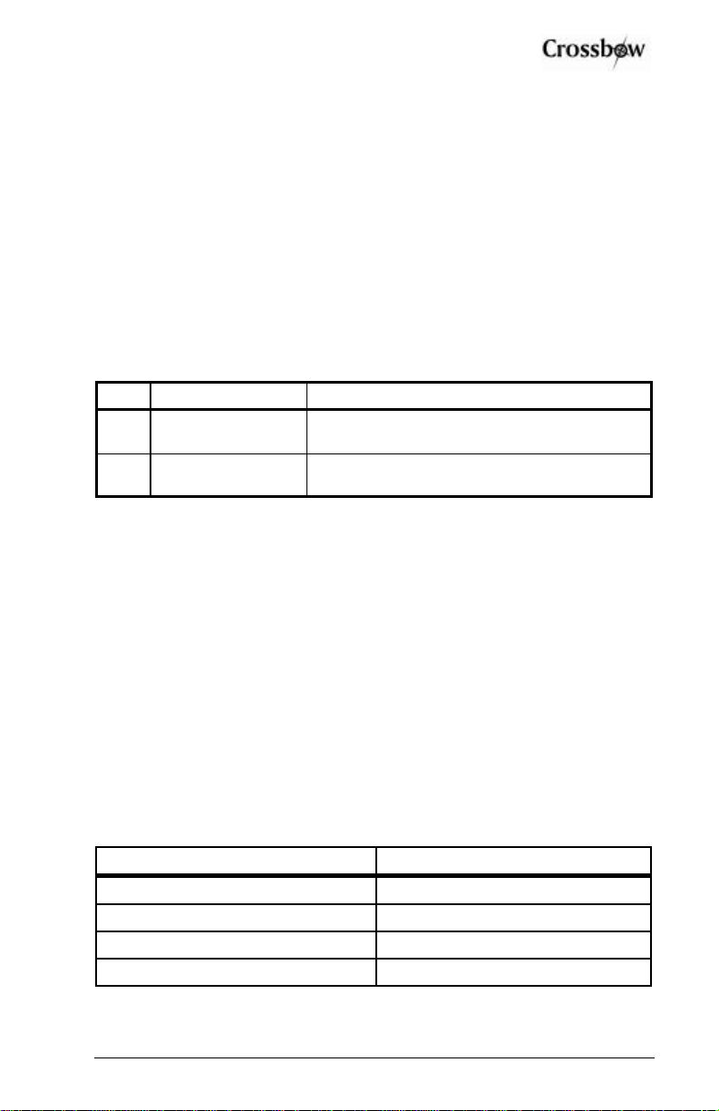
3.2.2 Power Input and Power Input Ground
The AHRS500CA power requirements are described in the table below. It
is designed to operate with either a nominal 14VDC or 28VDC aircraft
power system.
Table 2Electrical Power Input Requirements
Item Requirement AHRS500CA specification
1.
Input Supply
voltage 10-40 VDC
2.
Input Supply
Current 1 Amp (max)
3.2.3 Case Ground
The case is electrically connected to the I/O connector shell. The shell
should be electrically connected to the user’s cable shield. The case is
isolated from the Power Input Ground, and should be bolted to a good
conducting surface that is grounded.
3.2.4 Serial Data Interface
The serial interface is a factory configurable RS-422 or RS-232, also with
factory configurable baud rates (see table below) depending on the model
configuration chosen. In the final shipping configuration, the unit will
recognize certain commands detailed in Section 3.5. Data output is
continuous at a fixed frequencydependant on the baud rate (see Table 3
below).
Table 3Supported BAUD Rates and Output Rates
BAUD Rate Output Rate
9600 25
19200 50
38400 100
57600 200
SUNSTAR传感与控制 http://www.sensor-ic.com/ TEL:0755-83376549 FAX:0755-83376182 E-MAIL:[email protected]m
SUNSTAR自动化 http://www.sensor-ic.com/ TEL: 0755-83376489 FAX:0755-83376182 E-MAIL:[email protected]
AHRS500CA Series User’s Manual
Page 8Doc# 7430-0050-03 Rev. A
The unit has both an RS-232 and RS422 serial interface. During factory
configuration, one port is configured as the user data port while the other is
a factory diagnostic port to monitor BIT data. The unit can be configured to
allow either port to be the user data port, defaulting the other for BIT
diagnostics. The port definition is specified by the model configuration
chosen and will be detailed in the model configuration sheet shipped with
the unit.
3.2.5 BIT Status Output Pin
The BIT status output pin will become active high if the system is
experiencing a failure. The BIT is an open collector signal and requires a
pull-up resistor for proper operation.
3.2.6 Magnetometer calibration Input Pin
The AHRS500CA has an input pin to control the magnetometer hard-iron
calibration function. When this pin is active (low) the unit will collectthe
data necessary for magnetometer calibration. When it becomes inactive, the
magnetometer calibration data shall be used to compute the hard and soft
iron compensation values. During normal operation, no connection should
be made to this pin; this pinshall be tied high internally with a pull-up
resistor. This feature has been added as a means to perform a
Hardiron/Softiron calibration without sending the calibration commands to
the unit. Please see Appendix C, for a complete explanation of the
Hardiron/Softiron calibration process, and how this pin can be used as a
means of implementing the calibration.
3.2.7 No Connection
During normal operation of the AHRS500CA, no connection is made to the
factory test pin. This pin has an internal pull-up mechanism and must have
no connection for the AHRS500CA to operate properly.
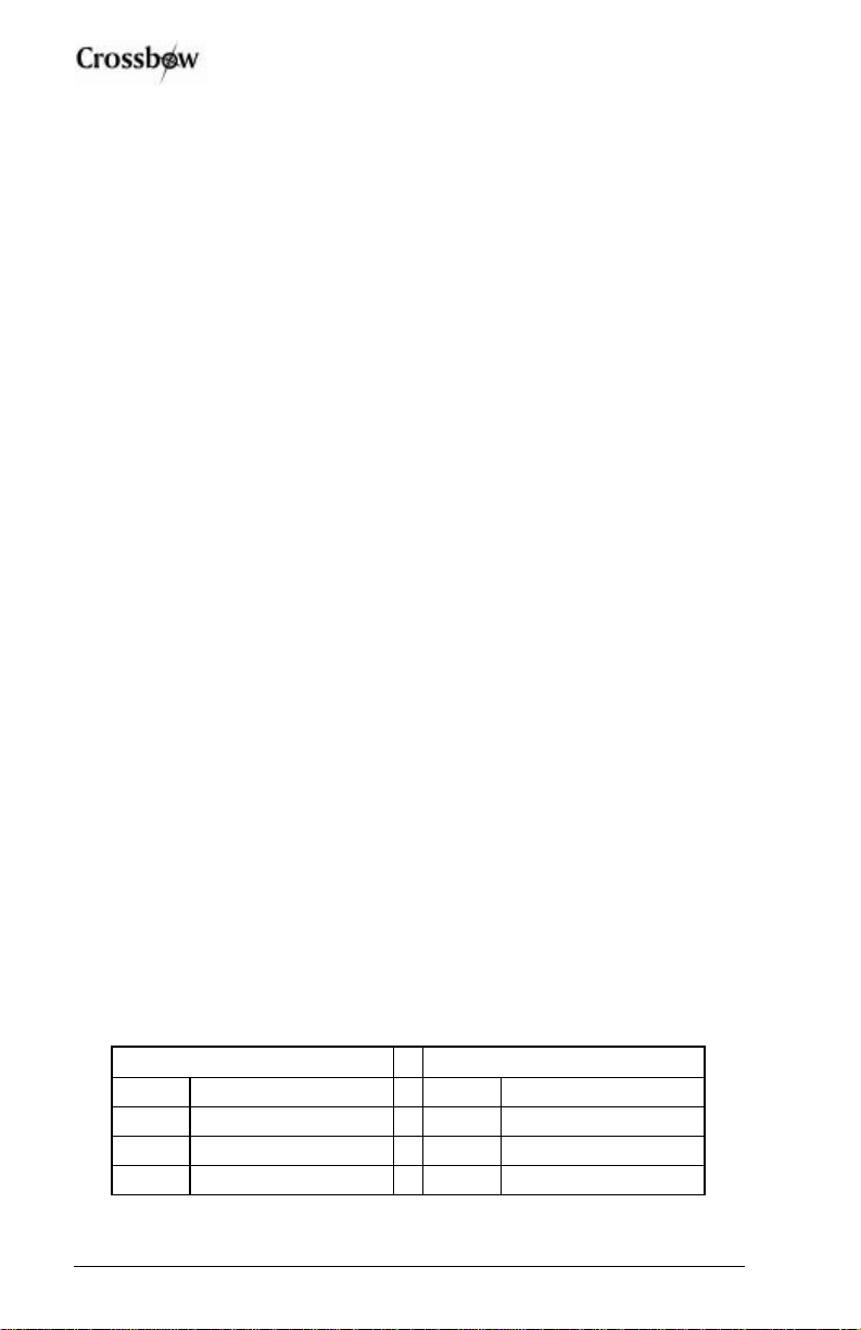
3.2.8 Quick Digital interface connection
On a standard DB-9 COM port connector, make the connections as
described in Table 4.
Table 4DB-9 COM Port Connections
COM Port Connector AHRS500CA Connector
Pin # Signal Pin # Signal
2RxD 1TxD
3TxD 2RxD
5GND* 4GND*
SUNSTAR传感与控制 http://www.sensor-ic.com/ TEL:0755-83376549 FAX:0755-83376182 E-MAIL:[email protected]m
SUNSTAR自动化 http://www.sensor-ic.com/ TEL: 0755-83376489 FAX:0755-83376182 E-MAIL:[email protected]

AHRS500CA Series User’s Manual
Doc# 7430-0050-03 Rev. A Page 9
*Note: Pin 4 on the AHRS500CA is data ground as well as power ground.
Power is applied to the AHRS500CA on pins 3 and 4. Pin 4 is ground; Pin
3 should have 10-40 VDC unregulated at 275 mA. DO NOT REVERSE
THE POWER LEADS.
3.3 Interface
The default serial interface is standard RS-232, model configurable baud
rate, 8 data bits, 1 start bit, 1 stop bit, no parity, and no flow control, and
will output at a model configurable output rate.
3.4 Measurements
The AHRS500CA Series is designed to operate as a complete attitude and
heading reference system. The default system operation is “angle” mode
with the packet and output data as described below. The AHRS500CA
operates in two other measurement modes that are for factory use only and
are not supported for general use.
The AHRS500CA acts as a complete attitude and heading reference system
and outputs the stabilized pitch, roll, and yaw angles along with the angular
rate and acceleration.
The Kalman filter operates to track the rate sensor bias and calculate the
stabilized roll, pitch, and yaw angles.
The AHRS500CA uses the angular rate sensors to integrate over your
rotational motion and find the actual pitch, roll, and yaw angles. The
AHRS500CA uses the accelerometers to correct for rate sensor drift in the
vertical angles (pitch and roll); the AHRS500CA uses the magnetometers to
correct for rate sensor drift in the yaw angle. This is the modern equivalent
of an analog vertical gyro that used a plumb bob in a feedback loop to keep
the gyro axis stabilized to vertical. The AHRS500CA takes advantage of
the rate gyros’ sensitivity to quick motions to maintain an accurate
orientation when accelerations would otherwise throw off the
accelerometers measurement of the AHRS500CA orientation relative to
gravity; the AHRS500CA then uses the accelerometers to provide long term
stability to keep the rate gyro drift in check.
The AHRS500CA uses a sophisticated Kalman filter algorithm to track the
bias in the rate sensors. This allows the AHRS500CA to use a very low
effective weighting on the accelerometers when the AHRS500CA is moved.
This makes the AHRS500CA very accurate in dynamic maneuvers.
The AHRS500CA outputs the stabilized pitch, roll and yaw angles in the
digital data packet. To convert the digital data to angle, use the following
relation:
SUNSTAR传感与控制 http://www.sensor-ic.com/ TEL:0755-83376549 FAX:0755-83376182 E-MAIL:[email protected]m
SUNSTAR自动化 http://www.sensor-ic.com/ TEL: 0755-83376489 FAX:0755-83376182 E-MAIL:[email protected]
AHRS500CA Series User’s Manual
Page 10 Doc# 7430-0050-03 Rev. A
angle = data*(SCALE)/215
where angle is the actual angle in degrees (pitch, roll or yaw), data is the
signed integer data output inthe data packet, and SCALEis a constant.
SCALE= 180°for roll, pitch and yaw.
To convert the acceleration data into G’s, use the following conversion:
accel = data*(10 * 1.5)/215
where accel is the actual measured acceleration in G’s, data is the digital
data sent by the AHRS500CA, and10 is the G Range for your
AHRS500CA. (The data is scaled so that 1 G = 9.80 m s-2.) This maximum
G range is a default value.
To convert the angular rate data into degrees per second, use the following
conversion:
rate = data*(800*1.5)/215
where rate is the actual measured angular rate in °/sec, data is the digital
data sent by the AHRS500CA, and800 is the Angular rate Range of the
AHRS500CA. This maximum angular rate is a default value.
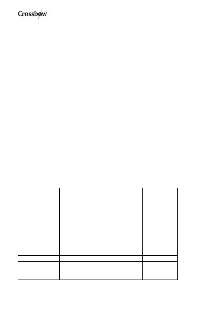
3.4.1 BIT Processing
The BIT message in each packet provides comprehensive information into
system health. The following information is supplied in the BIT byte fields
of the data packet. The table contains the actual bit definition present in the
two-byte output BIT field in the angle mode data packet (see section 3.6
below). The description defines the bit’s active (1) position.
Table 5Bit Message Definition
BIT Data Description Bit
Location
Hard Failure An unrecoverable failure has
occurred Bit 0
Soft Failure A soft failure has been detected. A
soft failure can be generated by any
BIT condition designated “soft”. If
the soft failure persists for more than
2100 data packets the Hard Failure
bit is turned on and the Soft Failure
bit is permanently on.
Bit 1
Not Ready The system is not ready to use Bit 2
Power Fail A power failure has been detected.
The system is on hold-up power and
is about to lose power.
Bit 3
SUNSTAR传感与控制 http://www.sensor-ic.com/ TEL:0755-83376549 FAX:0755-83376182 E-MAIL:[email protected]m
SUNSTAR自动化 http://www.sensor-ic.com/ TEL: 0755-83376489 FAX:0755-83376182 E-MAIL:[email protected]
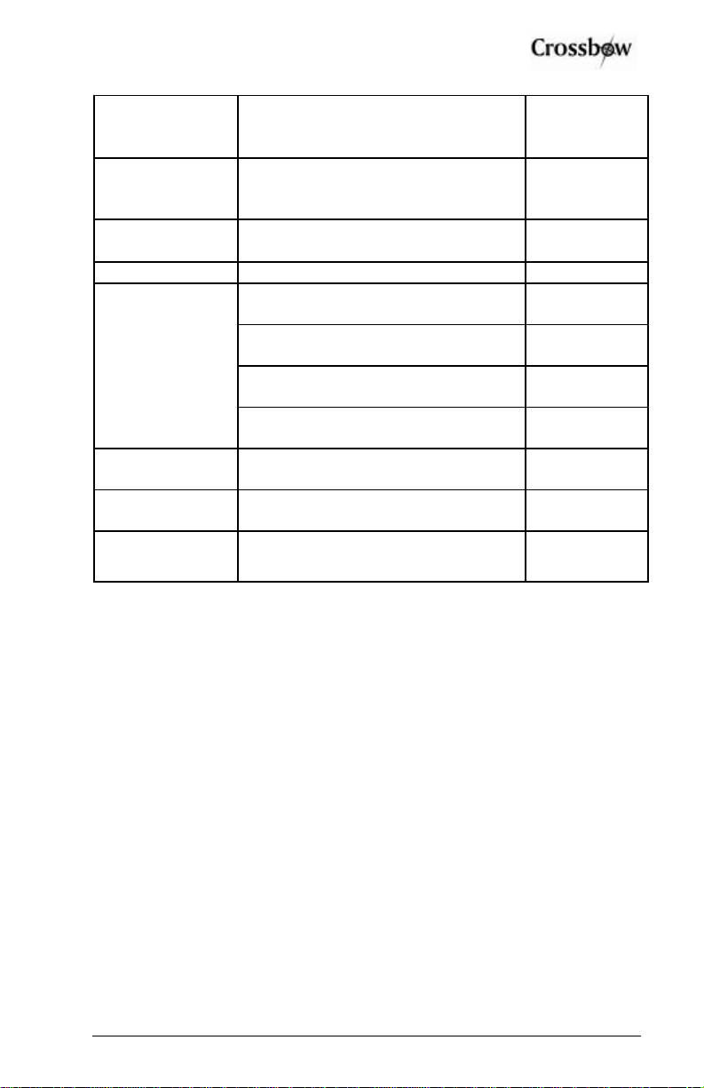
AHRS500CA Series User’s Manual
Doc# 7430-0050-03 Rev. A Page 11
Comm A serial port (user) communications
error (ex over-run, parity) has been
detected.
Bit 4
Reboot Detect A processor reset was detected
possibly due to a watchdog timeout
or low-power setting.
Bit 5
Calibration
Table A bad calibration table in flash
memory has been detected. Bit 6
Turn Indicator A turn has been detected Bit 8
Not ready, waiting for power-up or
post sensor saturation Bits 10,9: 11
Valid data but in initialization mode Bits 10,9: 10
Valid data but using only gyro
integration to provide attitude output Bits 10,9: 01
Algorithm Status
Full accuracy data Bits 10,9: 00
Magnetometer
Cal Status A Hardiron/Softiron calibration is
being performed. Bit 11
Magnetometer
Cal Validity Bad stored Hardiron/Softiron
calibration data has been detected Bit 12
Magnetometer
Cal Performance The Hardiron/Softiron calibration is
unsatisfactory
Bit 13
3.5 Commands
The AHRS500CA has a simple command structure. You send a command
consisting of one byte to the AHRS500CA over the RS-232 interface and
the AHRS500CA will execute the command.
XNOTE
The AHRS500CA commands are case sensitive!
GyroView is a very good tool to use when debugging your own software.
GyroView formulates the proper command structures and sends them over
the RS-232 interface. You can use GyroView to verify that the
AHRS500CA is functioning correctly. GyroView does not use any
commands that are not listed here.
XNOTE
With the exception of the change to Polled mode command (see below), the
commands listed below will only be operational when the unit is in polled
mode. When the unit is in continuous mode, only the change to Polled
mode command will be operational.
SUNSTAR传感与控制 http://www.sensor-ic.com/ TEL:0755-83376549 FAX:0755-83376182 E-MAIL:[email protected]m
SUNSTAR自动化 http://www.sensor-ic.com/ TEL: 0755-83376489 FAX:0755-83376182 E-MAIL:[email protected]

AHRS500CA Series User’s Manual
Page 12 Doc# 7430-0050-03 Rev. A
3.5.1 Command List
Command Ping
Character(s) Sent R
Response H
Description Pings AHRS500CA to verify communications
Command Voltage Mode
Character(s) Sent r
Response R
Description Factory use only
Command Scaled Mode
Character(s) Sent c
Response C
Description Factory use only
Command AHRS Mode
Character(s) Sent a
Response A
Description Changes measurement type to AHRS Mode.
AHRS500CA calculates stabilized pitch and roll,
and heading. Also outputs sensor measurements
in scaled engineering units.
Command Polled Mode
Character(s) Sent P
Response None
Description Changes data output mode to Polled Mode.
AHRS500CA will output a single data packet
when it receives a "G" command.
Command Continuous Mode
Character(s) Sent C
SUNSTAR传感与控制 http://www.sensor-ic.com/ TEL:0755-83376549 FAX:0755-83376182 E-MAIL:[email protected]m
SUNSTAR自动化 http://www.sensor-ic.com/ TEL: 0755-83376489 FAX:0755-83376182 E-MAIL:[email protected]

AHRS500CA Series User’s Manual
Doc# 7430-0050-03 Rev. A Page 13
Response Data Packets
Description Changes data output mode to Continuous Mode.
AHRS500CA will immediately start to output
data packets in continuous mode.
Command Request Data
Character(s) Sent G
Response Data Packet
Description "G" requests a single data packet. AHRS500CA
will respond with a data packet. Sending the
AHRS500CA a "G" while it is in Continuous
Mode will place the AHRS500CA in Polled
Mode.
Command Query AHRS500CA Version
Character(s) Sent v
Response ASCII String Packet
Description This queries the AHRS500CA firmware and will
tell you the AHRS500CA firmware version. The
response is an ASCII string packet that describes
the AHRS500CA firmware version, preceded
with a header byte (hex FF) and followed by a
one byte checksum calculated in the manner
described below (section 3.7).
Command Query Serial Number
Character(s) Sent S
Response Serial Number Packet
Description This queries the AHRS500CA for its serial
number. The AHRS500CA will respond with a
serial number data packet that consists of a
header byte (hex FF), the serial number in 4
bytes, and a checksum byte. The serial number
bytes should be interpreted as a 32-bit unsigned
integer. For example, the serial number 9911750
would be sent as the four bytes 00 97 3D C6.
SUNSTAR传感与控制 http://www.sensor-ic.com/ TEL:0755-83376549 FAX:0755-83376182 E-MAIL:[email protected]m
SUNSTAR自动化 http://www.sensor-ic.com/ TEL: 0755-83376489 FAX:0755-83376182 E-MAIL:[email protected]

AHRS500CA Series User’s Manual
Page 14 Doc# 7430-0050-03 Rev. A
Command Query Model
Character(s) Sent M
Response Model Configuration Packet
Description This queries the AHRS500CA model type and
will tell you the AHRS500CA model
configuration. The response is an ASCII string
packet that describes the model type
configuration, preceded with a header byte (hex
FF) and followed by a one byte checksum
calculated in the manner described below
(section 3.7).
3.6 Data Packet Format
In general, the digital data representing each measurement is sentas a 16-bit
number (two bytes). The data is sent MSB first then LSB.
In voltage mode, the data is sent as unsigned integers to represent the range
0 –5 V.
In scaled and angle mode, the data generally represents a quantity that can
be positive or negative. These numbers are sent as a 16-bit signed integer in
2's complement format. The data is sent as two bytes, MSB first then LSB.
Each data packet will begin with a two-byte header (hex AA 55) and end
with a two-byte checksum. The checksum is calculated in the following
manner:
1. Sum all packet contentsexcept header and checksum.
2. Divide the sum by hex FFFF.
3. The remainder should equal the checksum.
The packet also contains the model type configuration number, and the BIT
word output. Please refer to section 3.4.1 for details about the BIT word
processing.
The model type configuration number will display the model number of the
AHRS500CA model configuration purchased. In general the model type
configuration will be described in the model configuration sheet sent with
the unit, and is designated by the following string AHRS500CA-[]. The
number in the brackets is the model type configuration number output in the
angle mode data packet, and should match the model type purchased and
described in the configuration sheet.
SUNSTAR传感与控制 http://www.sensor-ic.com/ TEL:0755-83376549 FAX:0755-83376182 E-MAIL:[email protected]m
SUNSTAR自动化 http://www.sensor-ic.com/ TEL: 0755-83376489 FAX:0755-83376182 E-MAIL:[email protected]
Table of contents
Other Crossbow Technology Accessories manuals

Popular Accessories manuals by other brands

Alpine
Alpine KCE-510M user manual

Palram
Palram Patio Cover System 4200 Assembly instructions

XD COLLECTION
XD COLLECTION P322.45 Series manual

Adexi
Adexi Gastronoma 16310209 manual

Computherm
Computherm Q1RX operating instructions

S+S Regeltechnik
S+S Regeltechnik THERMASGARD ATF 1 Operating Instructions, Mounting & Installation


MyCharge
MyCharge Trek 2000 owner's manual

Endress+Hauser
Endress+Hauser Proline 300 Brief operating instructions

Indel Webasto
Indel Webasto U150X050P Installation and usage instructions

Aprilaire
Aprilaire 8056 Installation and operator's manual

Rohill Technologies
Rohill Technologies R-8070 manual

Winsen
Winsen GM-502B manual