Crouse-Hinds MTL1000 Series User manual

ii INM MTL1000 Rev 9
DRAFT - 05 DRAFT - 23 March 2021 February 2021
DECLARATION OF CONFORMITY
A printed version of the Declaration of Conformity has been provided separately within the original shipment of goods. However,
you can nd a copy of the latest version at http://www.mtl-inst.com/certicates

iii
INM MTL1000 Rev 9
DRAFT - 05 DRAFT - 23 March 2021 February 2021DRAFT - 05 DRAFT - 23 March 2021 February 2021
CONTENTS
DECLARATION OF CONFORMITY. . . . . . . . . . . . . . . . . . . . . . . . . . . . . . . . . . . . . . . . . . . . . . . . . . . . . . . . . ii
1 INTRODUCTION. ....................................................................1
1.1 General.................................................................................1
2 MTL1000 RANGE DESCRIPTION.......................................................1
2.1 Modules ................................................................................1
2.2 Accessories .............................................................................2
3 INSTALLATION PRECAUTIONS........................................................3
3.1 General.................................................................................3
3.2 Installation ..............................................................................3
3.2.1 Modules ...........................................................................3
3.2.2 Cabinet and enclosure mounting .........................................................3
4 COMMON SPECIFICATIONS ..........................................................4
5 MODULES.........................................................................5
5.1 MTL1991 Power feed and alarm module.......................................................5
5.2 Current repeaters .........................................................................5
5.2.1 MTL1141Transmitter repeater power supply...................................................5
5.2.2 MTL1142Transmitter repeater power supply with HART .........................................6
5.2.3 MTL1143Transmitter repeater power supply with HART and repeat output ..........................6
5.2.4 MTL1144 voltage/current input, loop powered isolator ...........................................7
Table 1 MTL1144 switch settings. . . . . . . . . . . . . . . . . . . . . . . . . . . . . . . . . . . . . . . . . . . . . . . . . . . . . . . . . . . . 7
5.2.5 MTL1145 loop powered current repeater .....................................................8
5.3 MTL1171,1172 temperature and MTL1173 potentiometer converters.................................9
Table 2 Conguration and DIP switch settings. . . . . . . . . . . . . . . . . . . . . . . . . . . . . . . . . . . . . . . . . . . . . . 9
Table 3 MTL1171 and MTL1172 range DIP switch setting . . . . . . . . . . . . . . . . . . . . . . . . . . . . . . . . . . . . . .9
5.3.1 MTL1171 thermocouple input converter .....................................................10
5.3.2 MTL1172 RTD input converter.............................................................10
5.3.3 MTL1173 Potentiometer input converter.....................................................10
5.4 MTL1211 Switch / Proximity Detector input....................................................11
5.5 MTL1249 Current / Voltage input/output repeater ...............................................11
Table 4 MTL1249 Dip Switch settings
. . . . . . . . . . . . . . . . . . . . . . . . . . . . . . . . . . . . . . . . . . . . . . . . . . . . .12
5.6 MTL1271, 1272 LOOP POWERED temperature converters .......................................13
5.7 MTL1271 loop powered thermocouple input converter...........................................14
5.8 MTL1272 loop powered RTD temperature converter............................................14
6 MTL13XXTRIP AMPLIFIERS .........................................................15
6.1 Introduction ............................................................................15
6.2 Trip level setting .........................................................................15
6.3 Label Indicators/Switches..................................................................15
6.4 Switch settings..........................................................................16
Table 5 Trip switch settings. . . . . . . . . . . . . . . . . . . . . . . . . . . . . . . . . . . . . . . . . . . . . . . . . . . . . . . . . . . . . . 16
Table 6 MTL137x Conguration and DIP switch settings . . . . . . . . . . . . . . . . . . . . . . . . . . . . . . . . . . . . . . .16
Table 7 MTL1371 and MTL1372 range DIP switch setting . . . . . . . . . . . . . . . . . . . . . . . . . . . . . . . . . . . . . . 16
6.5 MTL1321 trip amplifier with voltage/current input and 4-20mA output...............................17
6.6 MTL1341 trip amplifier with 4-20mA input/output...............................................18
6.7 MTL1371 trip amplifier converter, thermocouple input/4-20mA output...............................18
6.8 MTL1372 trip amplifier converter, RTD input/4-20mA output ......................................19
6.9 MTL1373 trip amplifier converter, Potentiometer input/4-20mA output ..............................19
7 MAINTENANCE ...................................................................20
7.1 Routine maintenance .....................................................................20
7.2 Enclosures .............................................................................20
8 APPENDIX A ......................................................................20
Table 8 Isolator current consumption for MTL1991 calculation @ 24V.. . . . . . . . . . . . . . . . . . . . . . . . . . . . . 16
iv INM MTL1000 Rev 9
DRAFT - 05 DRAFT - 23 March 2021 February 2021
IMPORTANT NOTE
This manual describes the installation and use of:
• MTL1000 range of isolating interfaces and accessories.
The MTL1000 products are designed to provide signal isolation and signal conversion between
equipment and areas of a process plant.
WARNING!
This equipment must be installed, operated and maintained only by trained
competent personnel and in accordance with all appropriate international, national
and local standard codes of practice and site regulations for process connected
apparatus and in accordance with the instructions contained here.
The following methods are used on the product and in this manual to alert the user
to important information:-
Caution - read the instructions
Caution - hot surface

1
INM MTL1000 Rev 9
DRAFT - 05 DRAFT - 23 March 2021 February 2021DRAFT - 05 DRAFT - 23 March 2021 February 2021
1 INTRODUCTION
1.1 General
This instruction manual describes the procedures for installing, connecting, checking and
maintaining MTL1000 range of isolating interfaces and accessories.The MTL1000 products are
designed to provide signal isolation and signal conversion between equipment and areas of a
process plant.
Signal isolation eliminates or reduces the risk of earth loops, surges and noise, all of which can
result in loss of signal integrity or damage to equipment. In addition, some modules offer the
ability to convert signal types to provide level compatibility between system components.
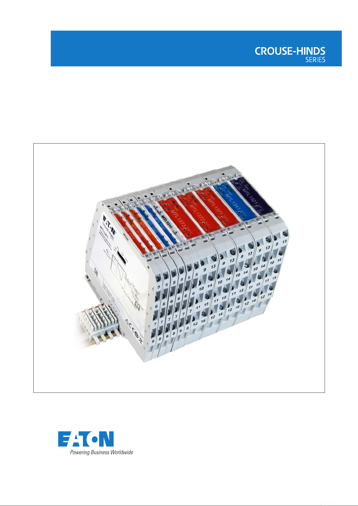
2 MTL1000 RANGE DESCRIPTION
The MTL1000 range of modules and accessories is designed for use with process connected
systems. It consists of compact isolating interface modules mounted on 35mm DIN rail. Power
is provided through a DIN rail mounted power bus, to which, the isolator module is plugged into
when clipped onto the DIN rail. Power is supplied to the isolators via a dedicated power feed
module which also provides current limit protection in the event of a fault.
The MTL1000 range modules provide power and status information via LEDs on the top of
the module. Where module conguration is required, then switches are accessed by the user
through the side cover.
2.1 Modules
The table below lists the modules in the MTL1000 range:
MTL1991 Power feed and alarm module
MTL1141 Transmitter repeater power supply
MTL1142 Transmitter repeater power supply with HART passthrough
MTL1143 Transmitter repeater power supply with HART passthrough and repeat output
MTL1144 V/I to current repeater, loop powered
MTL1171 Thermocouple input converter
MTL1172 Resistance temperature device (RTD) converter
MTL1173 Potentiometer input converter
MTL1271 Thermocouple input converter, loop powered
MTL1272 RTD converter, loop powered
MTL1211 Switch / Proximity detector input
MTL1249 Signal converter, V/I to V/I
MTL1341 Transmitter repeater with 2ch trip amp
MTL1321 Trip amplifier with voltage/current input
MTL1371 Trip amplifier withThermocouple input
MTL1372 Trip amplifier with RTD input
MTL1373 Trip amplifier with Potentiometer input
MTL1000 range - signal conditioning interfaces
2INM MTL1000 Rev 9
DRAFT - 05 DRAFT - 23 March 2021 February 2021
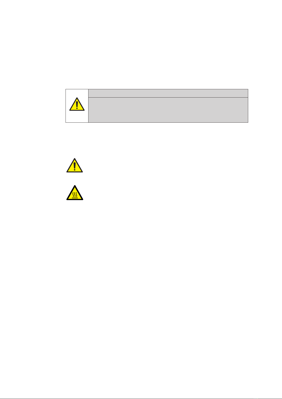
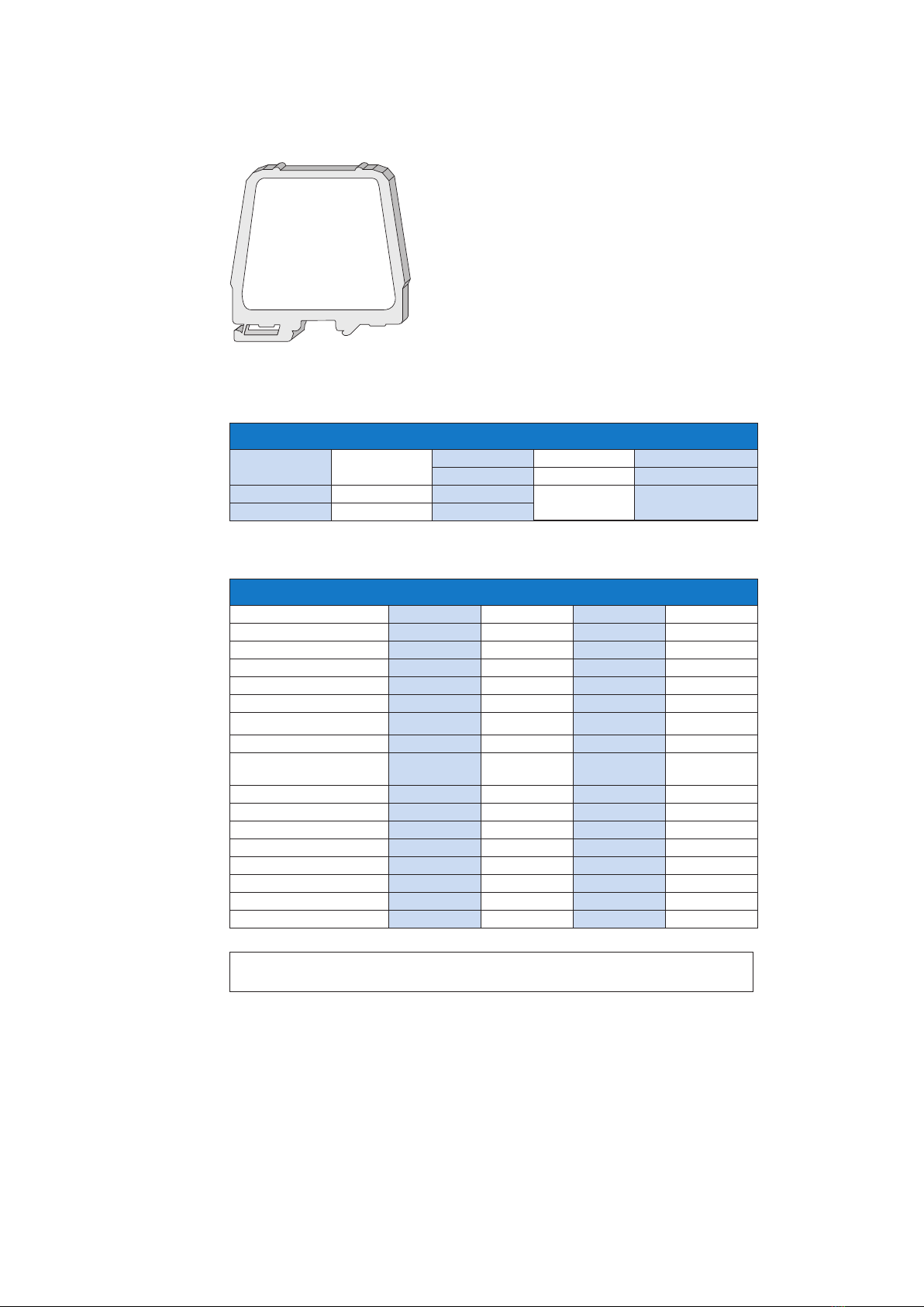
2.2 Accessories
PBUS6.2 DIN rail power bus connector for 2 module
positions (pack of 10)
PBUS17.5 DIN rail power bus connector for 1 module
position (pack of 10)
PBUS02 Power bus, direct connection terminals (1 set)
PBUS03 Module end stop
TH1000 Module tagging holder (pack of 20)
TH1300 Module tagging holder for MTL13xx
series. (pack of 10)
THR2 35mm x 7.5mm x 1m top hat standard
PBUS02
PBUS6.2
PBUS03
PBUS17.5
TH1000
TH1300
THR2
3
INM MTL1000 Rev 9
DRAFT - 05 DRAFT - 23 March 2021 February 2021DRAFT - 05 DRAFT - 23 March 2021 February 2021
3 INSTALLATION PRECAUTIONS
3.1 General
This equipment must be installed, operated and maintained only by trained competent
personnel and in accordance with all appropriate international, national and local standard codes
of practice and site regulations for apparatus and in accordance with the instructions contained
here.
3.2 Installation
3.2.1 Modules
All modules are DIN rail mounted in conjunction with the power bus connector.The power bus
must be installed on the DIN rst with the required number of slots for the modules that will be
tted. Each power bus connector powers 2 isolators.The MTL1991 power feed module, if used,
will occupy one position.This may be located in any position. Power may be connected directly
to the bus using the PBUS02 connector set.These are screw terminals that plug directly into
the power bus at either end of the bus.The power supply should be of the transformer isolated
type to obtain the secondary isolation required for SELV.
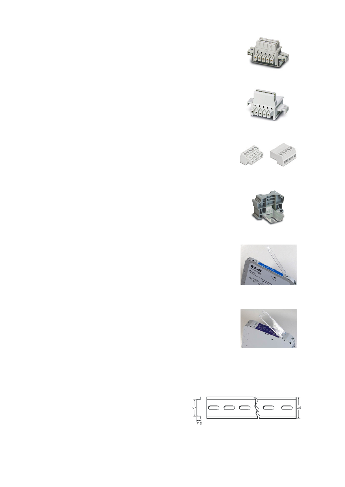
Modules are mounted on the DIN rail by clipping the foot, furthest from the release clip,
on to the DINrail rst. Rotate the module down onto the DIN rail and clip into place (Fig.1).
To release, use a atbladed screwdriver to release the module clip (Fig 2), hold module and
rotate clip upwards. (Fig.3)
3.2.2 Cabinet and enclosure mounting
The MTL1000 modules must be installed in a cabinet or enclosure with an impact
rating of at least 6.5J. Consideration must be given to the management of the internal
temperatures. Space must be provided around the modules to allow airflow.The optimum
transfer of heat is attained when the DIN rail is mounted horizontally but vertical DIN
rails may also be used where adequate space is available, especially in larger cabinets.
Principle sources of heat, such as power supplies, should be located above the modules.
An enclosure depth, measured from the base of the DIN rail, of at least 150mm is
recommended.The absolute minimum is 115mm.
CAUTION
Exercise care when removing modules in operation from the middle of a
group as the surface temperature on the side faces may be hot.
Fitting module to DIN rail Release clip Module removal
Fig. 1 Fig. 2 Fig. 3

4INM MTL1000 Rev 9
DRAFT - 05 DRAFT - 23 March 2021 February 2021
4 COMMON SPECIFICATIONS
For individual product specications please refer to individual product specication sheets.
Terminals
Screw clamp. Conductors of up to 13AWG / 1.8mm dia. stranded or single-
core copper.
Max torque 0.4Nm to 0.6Nm. Cable insulation strip /ferrule length 6-8mm
PBUS02 use wire type Solid / Stranded, 28 – 16 AWG / 0.14-1.3mm dia, – copper
Power supply voltage
18V to 32V DC SELV (UL listed where UL is applicable)
Isolation
250V ac or dc between power, eld and system circuits.
(tested to 1100Vac)
Mounting
T-section 35mm DIN rail (7.5mm or 15mm) to EN 50022
Ambient temperature limits
-20 to +60°C (-6 to +140°F) operating
-40 to +80°C (-40 to +176°F) storage
Humidity
5 to 95% relative humidity
Altitude
<2000m
Weight
6.2mm modules120g,
17.5mm modules 130g
EMC
EN61326 and NE21* Class A equipment
* For 20mS power interruption compliance, a suitable power supply must be used.
Dimensions
Fig. 1 MTL1000 Fig. 2 MTL1300
5
INM MTL1000 Rev 9
DRAFT - 05 DRAFT - 23 March 2021 February 2021DRAFT - 05 DRAFT - 23 March 2021 February 2021
5 MODULES
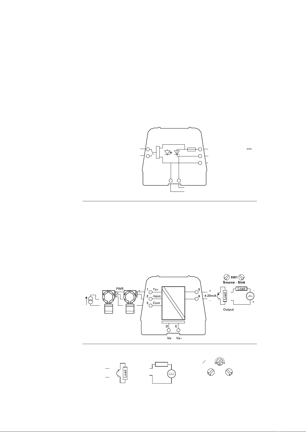
5.1 MTL1991 power feed and alarm module
The MTL1991 module is required to feed power to a group of MTL1000 range modules
via the DIN rail power bus. Each power feed module provides reverse voltage protection
and power monitoring. The power monitor relay provides a dry contact output which
may be used for connection into a monitoring system or local indicator.
The number of isolators connected to any one power feed module must be assessed
for power consumption. The maximum load current when feeding power via terminal
5 is 1A. If redundant power inputs are not required then terminal 6 may be used and
a maximum load current of 2 A is acceptable. Check current consumption table in
Appendix A for details. If power is fed directly into terminal 6 and external 3A time delay
fuse must be tted. Alarm relay contact rating is 40Vrms ac/dc 0.5A, resistive.
Where redundant power feeds are required, two MTL1991 modules are tted with one
power feed on each. The maximum load current is 1A.
5.2 Current repeaters
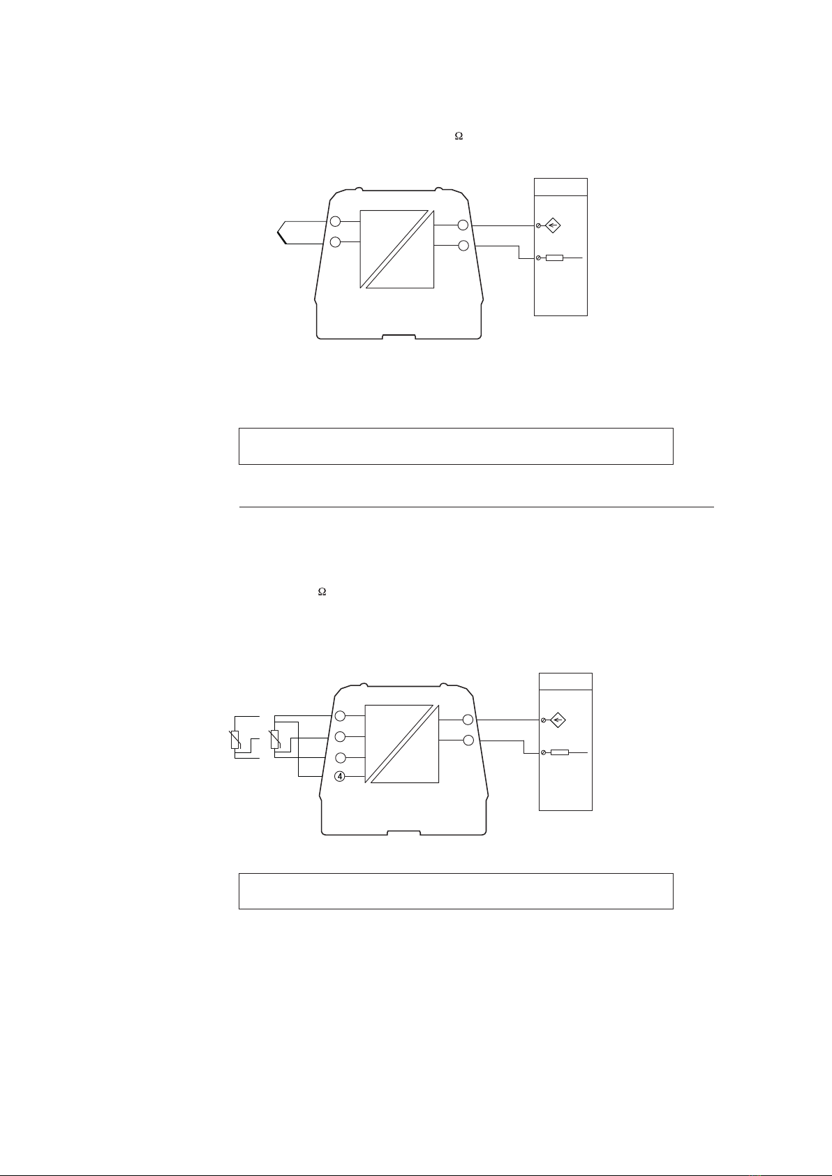
5.2.1 MTL1141 transmitter repeater power supply
Before installing this modules check the connection requirements on the ‘system’ side
of the module.The output may be congured to source or sink current. Current source
is used when the input to the system is passive, ie there is no power supply present
and it presents a resistive load. Current sink is used mainly with a ‘2 wire’ transmitter
input to the system where ‘loop power’ and ‘input’ terminals are provided. Terminal
6 on the MTL1141 is connected to the transmitter supply, and terminal 5 to the input.
See Fig.4. Switch SW1 on the module must be set prior to installation.The module is
supplied with the switch set in ‘source’ mode.
V+ supply input 19-32V dc 1A
D E
ALARM
1
2
5
6
7
2A
Direct V+ supply input (max 2A)
V- supply input
Bus supply output
Vs+
Vs-
MTL1991
MTL1141
Source output
5 +
6
-
4-20mA
Load
Sink output
5
6
-
+
-
+
Power
Label side of module
SW1
Source - Sink
SW1
34turn
Fig. 4 Fig. 5
Source output
5 +
6
-
4-20mA
Load
Sink output
5
6
-
+
-
+
Power
Label side of module
SW1
Source - Sink
SW1
34turn

6INM MTL1000 Rev 9
DRAFT - 05 DRAFT - 23 March 2021 February 2021
5.2.2 MTL1142 transmitter repeater power supply with HART
Before installing this modules check the connection requirements on the ‘system’ side
of the module.The output may be congured to source or sink current. Current source
is used when the input to the system is passive, i.e. there is no power supply present
and it presents a resistive load. Current sink is used mainly with a ‘2 wire’ transmitter
input to the system where ‘loop power’ and ‘input’ terminals are provided. Terminal
6 on the MTL1142 is connected to the transmitter supply, and terminal 5 to the input.
Switch SW1 on the module must be set prior to installation.The module is supplied
with the switch set in ‘source’ mode. HART communications are passed with both
settings. In source mode the input impedance on the system input must be >240Ω for
HART compliance.
5.2.3 MTL1143 transmitter repeater power supply with HART and repeat output
Before installing this modules check the connection requirements on the ‘system’ side
of the module. Output 1 is congured to source current into a load and provide HART
communications passthrough.
Output 2 on terminals 7 and 8 generates a repeat 4-20mA signal to another device.This
output provides a 4-20mA ‘source’ current to the system input. HART communication
is not provided via this output.
An active current source may also be applied via terminals 2 and 3. HART
communications are not provided when operating in this mode.
PWR
+
-
Tx+
Input
Com
1
2
3
5
6
D E
Vs- Vs+
4-20mA
+
-+
-
Output
+
-
Load
Load
SW1
Source - Sink
MTL1142
Tx+
Input
Com
1
2
3
5
6
D E
Vs- Vs+
4-20mA
+
-
Load
7
84-20mA
+
-
Load
Output 1
Output 2
PWR
+
-
+
-
MTL1143
7
INM MTL1000 Rev 9
DRAFT - 05 DRAFT - 23 March 2021 February 2021DRAFT - 05 DRAFT - 23 March 2021 February 2021
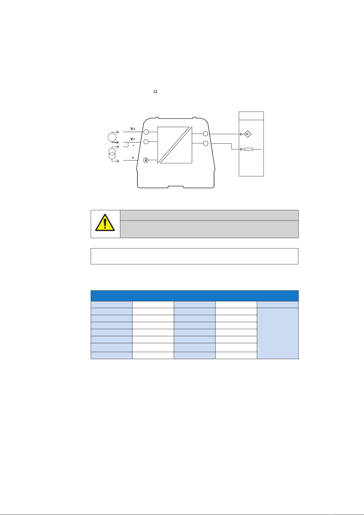
5.2.4 MTL1144 voltage/current input, loop powered isolator
The MTL1144 provides an interface to convert voltage or current signals into 4-20mA for
connection to a system analogue input. Switches are used to select the required input
range.The input terminals are chosen depending on signal type, 1 and 2 for voltage
input and 2 and 4 for current input.
The maximum load resistance is dependent on the available power supply voltage.
Max load = 50(Vs-17)
CAUTION
Do not connect a low impedance voltage source to terminals 2 and 4, damage
may result.
NOTE
Signal source must be isolated from mains supply.
Table 1
MTL1144 switch settings
DS1 DS2 DS3 Input Output
OFF OFF OFF 0-1V
4-20mA
ON OFF OFF 0-5V
OFF ON OFF 0-10V
ON ON OFF 1-5V
OFF OFF ON 0-20mA
ON OFF ON 4-20mA
OFF ON ON 0-100mV
MTL1144
5
6
2
1+
-
System AI
+24V Tx
Power
Limit
2 wire Tx
system input
Load
-ve
Return
V/I
I
I
V
I
I
4-20mA

8INM MTL1000 Rev 9
DRAFT - 05 DRAFT - 23 March 2021 February 2021
5.2.5 MTL1145 loop powered current repeater
The MTL1145 can be used for both input and output applications. It is primarily
designed for use with analogue outputs and loop powered from the system
output. Power is taken from the analogue output signal to power the isolator. HART
communication passthrough is not provided by this module.
Alternatively the module can be used in a current sink mode where an analogue output
in the eld can be connected to pass a signal into a system input. Power is taken from
theTransmitter power connection on the system and the signal is fed back through the
system input load to 0V.
NOTE
Greater accuracy is provided when operating in Current Source mode.
Signal source must be isolated from mains supply.
MTL1145
Current Source
(Analogue Outpt /Input)
System AO
O/P+
O/P-
I/P converter
/ AI Load
+
-
System AI
MTL1145
Input
Current Sink
(Analogue Input)
2 wire
Tx
Power
Input +
V source
(24V)
Channel
Input
0V / Return
System AI

9
INM MTL1000 Rev 9
DRAFT - 05 DRAFT - 23 March 2021 February 2021DRAFT - 05 DRAFT - 23 March 2021 February 2021
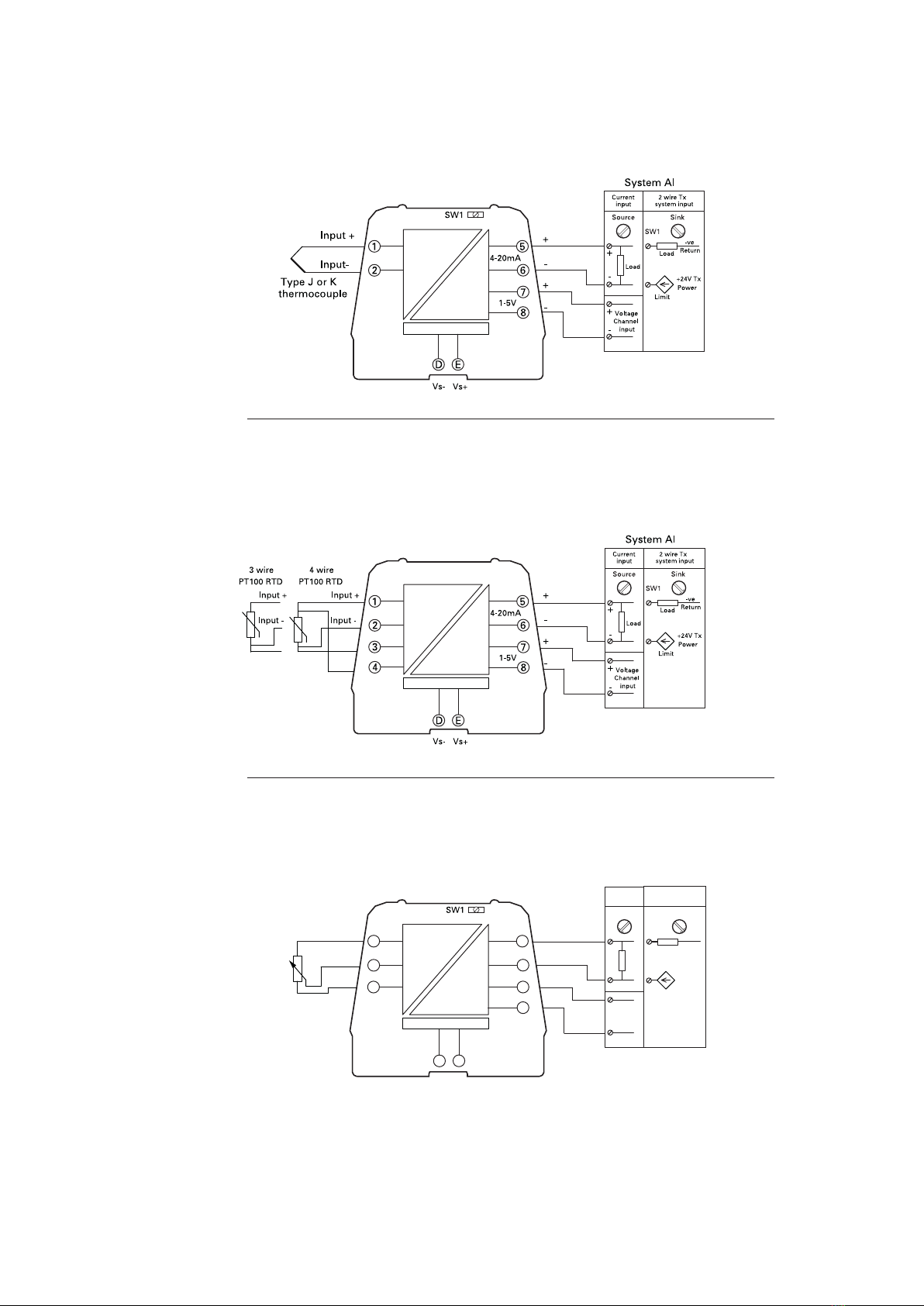
5.3 MTL1171, 1172 temperature and MTL1173
potentiometer converters
The MTL1171, for thermocouples and MTL1172, for RTD,
convert low level temperature inputs to 4-20mA. Input type
and range setting is performed using switches on the side
of the module. The MTL1173 is for a potentiometer input,
there are no switches on this module.
The sensor types and wire break detection are selected
using switches DS 1-4 and a selection of popular ranges is
available using switches DS 6-9.
See tables 1 and 2.
Current output, voltage output or current sink output is available on the
system terminals by wiring to the appropriate terminals as shown and
setting SW1 to the appropriate position.
Condition Green (PWR) Red (STS)
Power ON/ Normal ON OFF
Power LowVoltage OFF OFF
Field Open circuit ON Flashing
Module failure ON ON
Table 2 Conguration and DIP switch settings
Model Input type DS1 DS2 DS3 DS4 DS5
Type Wire Break Wire Break Drive Trip 1 Trip 2
MTL1x71 THC J Off / K On ON/OFF ON = Upscale
OFF = Downscale N/A N/AMTL1x72 RTD 4W Off 3W On
MTL1173 POT -
Table 3 MTL1171 and MTL1172 range DIP switch setting
RangeTHC/RTD DS6 DS7 DS8 DS9 DS10
0 to 100°C 0000-
0 to 150°C 0001-
0 to 200°C 0010-
0 to 350°C 0011-
0 to 500°C 0100-
0 to 650°C 0101-
0 to 800°C 0110-
0 to 1000°C
(RTD max 850°C) 0111-
-10 to 50°C 1000-
-50 to 50°C 1001-
-50 to 100°C 1010-
-50 to 150°C 1011-
-50 to 250°C 1100-
-50 to 350°C 1101-
-200 to 600°C 1110-
Special (Reserved) 1111-
NOTE
Cycle power supply after setting switches
SW1
Source Sink
LED indicators show
the power and eld
input status
SW1
DS10
MTL117x
DS1
10 INM MTL1000 Rev 9
DRAFT-05DRAFT-23March2021 February2021
MTL1172
MTL1171
5.3.1 MTL1171 thermocouple input converter
ForType J or K thermocouples. Cold junction compensation is provided by the MTL1171.
Switch settings select open wire detection and up/down scale drive.
5.3.2 MTL1172 RTD input converter
For PT100 RTD sensors. Switch settings select 3 or 4 wire connection and open wire
detection with up/down scale drive.
5.3.3 MTL1173 potentiometer input converter
Potentiometer Input.
MTL1173
ED
5
62
1
4-20mA
7
8
1-5V
+
-
+
-
Potentiometer
input
3
Load
System AI
+
-
Current
input
Voltage
Channel
input
+24V Tx
Power
Limit
2 wire Tx
system input
-
+
SW1
Source Sink
Load
-ve
Return
+24V
11
INM MTL1000 Rev 9
DRAFT - 05 DRAFT - 23 March 2021 February 2021DRAFT - 05 DRAFT - 23 March 2021 February 2021
5.4 MTL1211 Switch / Proximity Detector input
Switch or proximity detector isolator with the option to select line fault detection or a
repeat output Switches are used to select phase reversal and the repeat output or LFD
alarm output .
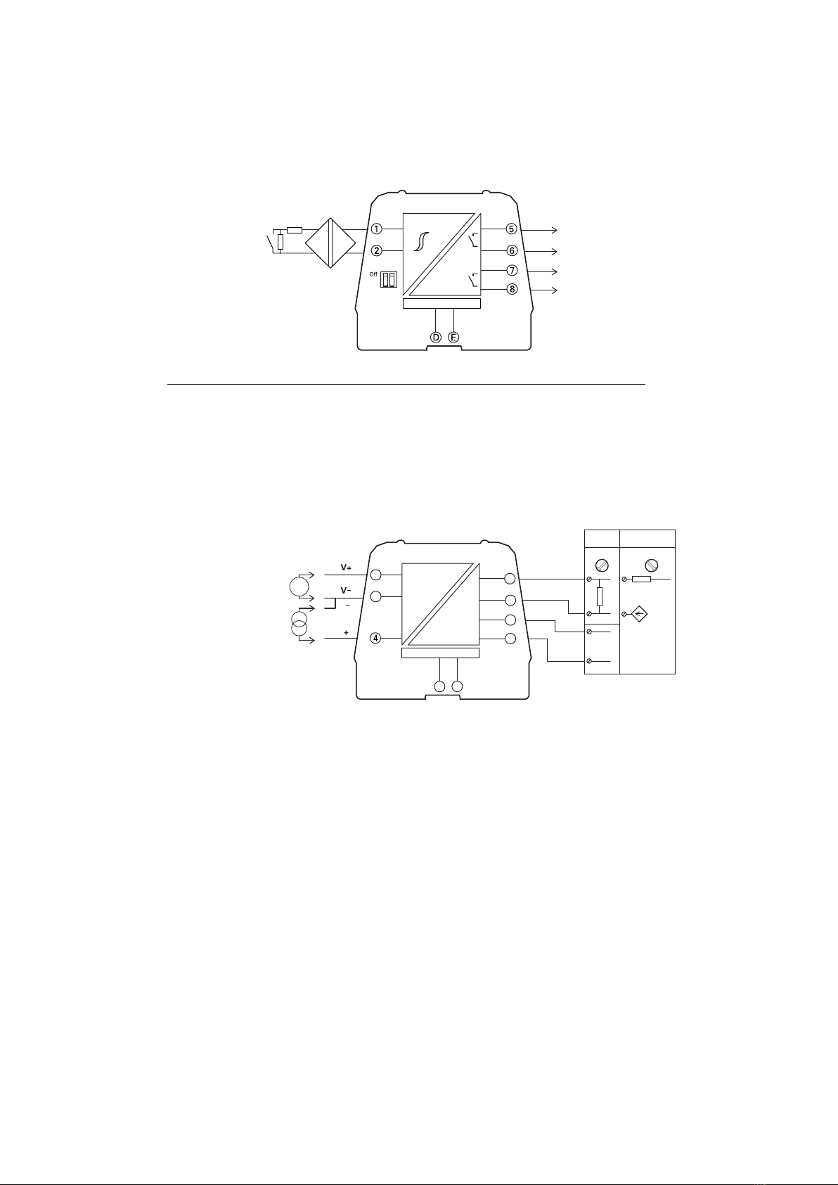
5.5 MTL1249 Current /Voltage input/output repeater
The MTL1249 is a single channel signal conditioner which can accept voltage or current
inputs and provide a voltage or current output.The signal levels are selected by the user
using switches on the module as shown in the table 3.
MTL1211
Output
Repeat/LFD
+24V
+
_
680Ω
22kΩ
On
LFD PR
MTL1249
ED
5
6
2
1
7
8
+
-
+
-
Load
System AI
+
-
Current
input
Voltage
Channel
input
+24V Tx
Power
Limit
2 wire Tx
system input
-
+
SW1
Source Sink
Load
-ve
Return
+24V
V/I
V/I
I
V
V
I
I

12 INM MTL1000 Rev 9
DRAFT - 05 DRAFT - 23 March 2021 February 2021
Table 4 MTL1249 Dip Switch settings
INPUT DS1 DS2 DS3 DS4 DS5 DS6 INPUT OUTPUT
Voltage
OFF OFF OFF OFF OFF OFF 0-1V
4-20mA
ON OFF OFF OFF OFF OFF 0-5V
OFF ON OFF OFF OFF OFF 0-10V
ON ON OFF OFF OFF OFF 1-5V
Current OFF OFF ON OFF OFF OFF 0-20mA
ON OFF ON OFF OFF OFF 4-20mA
Voltage
OFF ON ON OFF OFF OFF 0-1V
0-20mA
ON ON ON OFF OFF OFF 0-5V
OFF OFF OFF ON OFF OFF 0-10V
ON OFF OFF ON OFF OFF 1-5V
Current OFF ON OFF ON OFF OFF 0-20mA
ON ON OFF ON OFF OFF 4-20mA
Voltage
OFF OFF ON ON OFF OFF 0-1V
0-5V
ON OFF ON ON OFF OFF 0-5V
OFF ON ON ON OFF OFF 0-10V
ON ON ON ON OFF OFF 1-5V
Current OFF OFF OFF OFF ON OFF 0-20mA
ON OFF OFF OFF ON OFF 4-20mA
Voltage
OFF ON OFF OFF ON OFF 0-1V
1-5V
ON ON OFF OFF ON OFF 0-5V
OFF OFF ON OFF ON OFF 0-10V
ON OFF ON OFF ON OFF 1-5V
Current OFF ON ON OFF ON OFF 0-20mA
ON ON ON OFF ON OFF 4-20mA
Voltage
OFF OFF OFF ON ON OFF 0-1V
0-10V
ON OFF OFF ON ON OFF 0-5V
OFF ON OFF ON ON OFF 0-10V
ON ON OFF ON ON OFF 1-5V
Current OFF OFF ON ON ON OFF 0-20mA
ON OFF ON ON ON OFF 4-20mA
Voltage
OFF ON ON ON ON OFF 0-1V
2-10V
ON ON ON ON ON OFF 0-5V
OFF OFF OFF OFF OFF ON 0-10V
ON OFF OFF OFF OFF ON 1-5V
Current OFF ON OFF OFF OFF ON 0-20mA
ON ON OFF OFF OFF ON 4-20mA
Voltage
OFF OFF ON OFF OFF ON 0-100mV 4-20mA
ON OFF ON OFF OFF ON 0-100mV 0-20mA
OFF ON ON OFF OFF ON 0-100mV 0-5V
ON ON ON OFF OFF ON 0-100mV 1-5V
OFF OFF OFF ON OFF ON 0-100mV 0-10V
ON OFF OFF ON OFF ON 0-100mV 2-10V
13
INM MTL1000 Rev 9
DRAFT - 05 DRAFT - 23 March 2021 February 2021DRAFT - 05 DRAFT - 23 March 2021 February 2021
5.6 MTL1271, 1272 LOOP POWERED temperature converters
The MTL1271, for thermocouples and MTL1272, for RTD,
convert low level temperature inputs to 4-20mA. Input type
and range setting is performed using switches on the side
of the module.
The sensor types and wire break detection are selected
using switches DS 1-3 and a selection of popular ranges is
available using switches DS 4-7.
See tables 1 and 2.
Table 1
Conguration and DIP switch settings
Model Input type DS1 DS2 DS3
Type Wire Break Wire Break Drive
MTL1171 THC J Off / K On ON/OFF ON = Upscale
OFF = Downscale
MTL1172 RTD 4W Off 3W On
Table 2
MTL1271 and MTL1272 range DIP switch setting
RangeTHC/RTD DS4 DS5 DS6 DS7
0 to 100°C 0 0 0 0
0 to 150°C 0 0 0 1
0 to 200°C 0 0 1 0
0 to 350°C 0 0 1 1
0 to 500°C 0 1 0 0
0 to 650°C 0 1 0 1
0 to 800°C 0 1 1 0
0 to 1000°C
(RTD max 850°C) 0 1 1 1
-10 to 50°C 1 0 0 0
-50 to 50°C 1 0 0 1
-50 to 100°C 1 0 1 0
-50 to 150°C 1 0 1 1
-50 to 250°C 1 1 0 0
-50 to 350°C 1 1 0 1
-200 to 600°C 1 1 1 0
Special (Reserved) 1 1 1 1
NOTE
Cycle power supply after setting switches
MTL127x
14 INM MTL1000 Rev 9
DRAFT - 05 DRAFT - 23 March 2021 February 2021
5.7 MTL1271 loop powered thermocouple input converterFor use
withType J or K thermocouples. Range and thermocouple type are set by use of DP
switches on the module.The maximum load resistance is dependent on the available
power supply voltage. Max load = 50(Vs-17)
For range settings please refer toTable 1 for MTL1271/72. Note, no LED indicators are
tted on the loop powered modules.
NOTE
Signal source must be isolated from mains supply.
5.8 MTL1272 loop powered RTD temperature converter
For use with PT100 type sensors. Range is set by use of DP switches on the module.
The maximum load resistance is dependent on the available power supply voltage.Max
load = 50(Vs-17)
ForrangesettingspleaserefertoTable1and2forMTL1271/72.Note,noLEDindicatorsare
tted on the loop powered modules.
NOTE
Signal source must be isolated from mains supply.
Input+
MTL1271
5
6
2
1+
-
System AI
2 wire Tx
system input
Input-
Load
-ve
Return
+24V Tx
Power
Limit
4-20mA
Type J or K
thermocouple
Input+
MTL1272
5
6
2
1+
-
System AI
2 wire Tx
system input
Input-
Load
-ve
Return
+24V Tx
Power
Limit
4-20mA
3
3 wire
PT100 RTD
4 wire
PT100 RTD
Input+
Input-
15
INM MTL1000 Rev 9
DRAFT - 05 DRAFT - 23 March 2021 February 2021DRAFT - 05 DRAFT - 23 March 2021 February 2021
6 MTL13XXTRIP AMPLIFIERS
6.1 Introduction
The trip amplier modules all use the 17.5mm wide housing with up to 16 terminals
available for eld and system connections. Power can be supplied via the DIN rail power
bus, using the PBUS17.5 power connectors, or directly into the module via screw
terminals 15 and 16.Where the power bus is being used it is recommended power is
fed directly to the bus using the PBUS02 or MTL1991 power feed connections.Two trip
points may be set with high or low level switching.
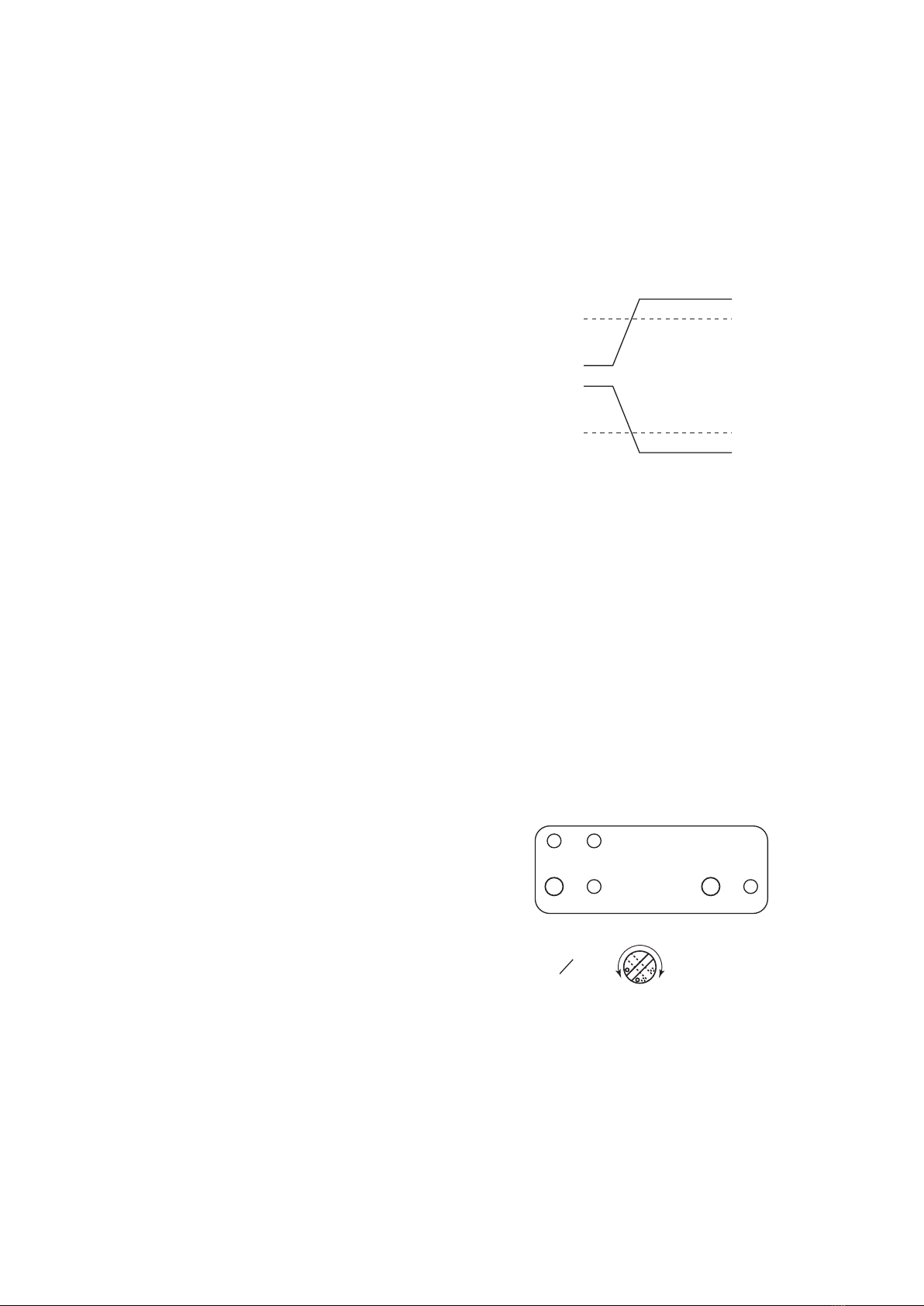
6.2 Trip level setting
Before setting the trip level the relay
switching action must be set to HighTrip
or LowTrip using the switches on the
side of the module. It is normal to set the
relay so that under non-alarm conditions
the relay contacts are closed.When in
alarm, the relay contacts would normally
be set to open, this will also be the state
when the module is unpowered (failsafe
operation).
DS4 / DS5 Off – High trip, On – Low trip Set these switches with the module off the
DIN rail.
The yellowTrip LEDs are illuminated when the relays are energised.
The switching point for either trip is set by feeding the required process trip level into
the input of the module and pressing one of the two small ‘SET’ buttons on the top of
the module for the appropriate trip.The Power and STS light will ash 5 times.The level
is digitally stored in the module and retained in the event of power loss. Pressing the
SET button again will overwrite the previous setting to the current input level that is
beingapplied at the time.
All models also provide a 4-20mA output which can be set for current source (active) or
current sink (passive) operation as required.
6.3 Label Indicators / Switches
STS RED Off normal operation. On fault. Flashing - temperature input open circuit
PWR GREEN on when power applied
Trip 1YELLOW on when relay 1 energised
Trip 2YELLOW on when relay 2 energised
DSx DIP switches for mode setting
SW1 Current output Sink / Source setting
Relay Off - Contacts open
Relay On - Contacts closed
Relay On - Contacts closed
Relay Off - Contacts open
Set point
Set point
High Trip
Low Trip
STS PWR
O/PSET
TRIP 1 MTL13xx
O/PSET
TRIP 2
SW1
34turn
16 INM MTL1000 Rev 9
DRAFT - 05 DRAFT - 23 March 2021 February 2021
6.4 Switch settings
Table 1
Trip switch settings
MTL13xx
DS4 (trip 1) DS5 (trip 2) Status
ON ON Trip alarm low
OFF OFF Trip alarm high
Table 2
MTL137x Conguration and DIP switch settings
Model Input type DS1 DS2 DS3 DS4 DS5
Type Wire Break Wire Break Drive Trip 1 Trip 2
MTL1371 THC J Off / K On ON/OFF ON = Upscale
OFF = Downscale Off High
On Low
Off High
On Low
MTL1372 RTD 4W Off 3W On
MTL1373 POT -
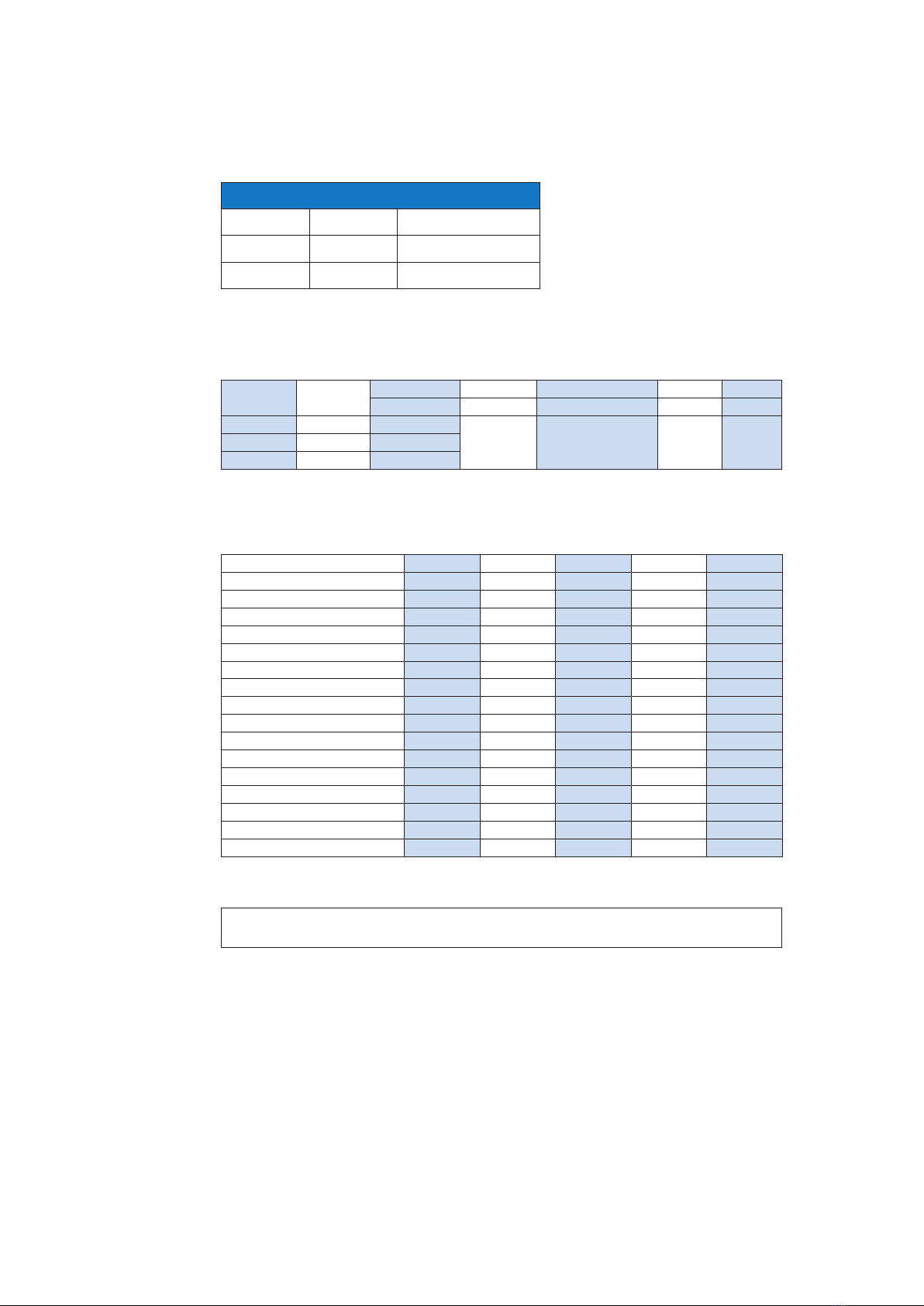
Table 3
MTL1371 and MTL1372 range DIP switch setting
RangeTHC/RTD DS6 DS7 DS8 DS9 DS10
0 to 100°C 0 0 0 0 -
0 to 150°C 0001-
0 to 200°C 0 0 1 0 -
0 to 350°C 0 0 1 1 -
0 to 500°C 0100-
0 to 650°C 0 1 0 1 -
0 to 800°C 0110-
0 to 1000°C (RTD max 850°C) 0 1 1 1 -
-10 to 50°C 1 0 0 0 -
-50 to 50°C 1001-
-50 to 100°C 1 0 1 0 -
-50 to 150°C 1011-
-50 to 250°C 1 1 0 0 -
-50 to 350°C 1 1 0 1 -
-200 to 600°C 1110-
Special (Reserved) 1 1 1 1 -
NOTE
Cycle power supply after setting switches
This manual suits for next models
17
Table of contents
Popular Industrial Equipment manuals by other brands

ABB
ABB AMXE132 instructions

National Instruments
National Instruments NI-9207 Getting started

Cognex
Cognex In-Sight 3800 Series Reference manual

LNS
LNS Hydrobar Express 220 Startup manual

Miller Weldmaster
Miller Weldmaster Extreme T300 operating manual

Mayr
Mayr ROBA 8981.29 01 Series Original operating instructions


