Fromm FS395 Series Setup guide

1
It is prohibited to duplicate this manual or parts of this in any way or shape, without the written consent of the author © 2023
Translation of original instructions
SEMI-AUTOMATIC WRAPPER
Series FS395
FS395.V01.EN01
IMPORTANT!
Read the instructions carefully before installing and before using this machine for the
first time. so as to avoid causing damage to yourself and to your machine.
Store for further consultation.

2 It is prohibited to duplicate this manual or parts of this in any way or shape, without the written consent of the author © 2023
INDEX
CH. 1. CONTENTS AND CONSULTATION METHOD...........................................................................................................3
1.1. PURPOSE OF THE MANUAL..........................................................................................................................................3
1.1.1 IMPORTANCE OF THE MANUAL...................................................................................................................................3
1.1.2. STORAGE, UPDATES, ADDITIONS AND REPLACEMENT...........................................................................................3
1.2. MEANING OF THE SYMBOLS........................................................................................................................................4
1.3. DEFINITIONS ..................................................................................................................................................................6
CH. 2. GENERAL INFORMATION AND CHARACTERISTICS ..............................................................................................9
2.1. TECHNICAL FEATURES.................................................................................................................................................9
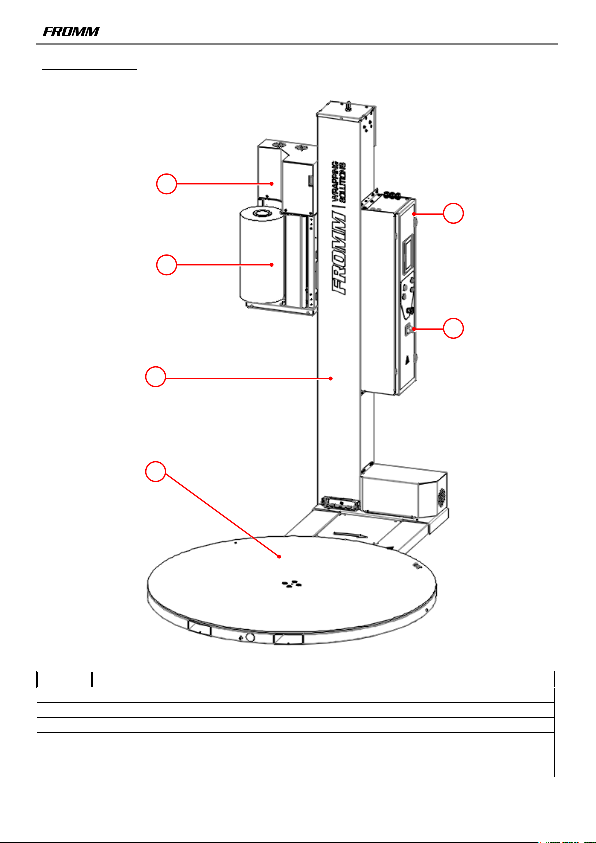
2.1.1. PURPOSE - AIM - CONSTRUCTIVE PARTS..................................................................................................................9
2.1.2. PERFORMANCE...........................................................................................................................................................11
2.1.3. TECHNICAL AND CONSTRUCTIVE DATA OF SUPPLY .............................................................................................11
2.2. PROCESSED PRODUCTS - HANDLED OR GENERATED..........................................................................................11
2.3. EMISSION OF AIRBORNE NOISE................................................................................................................................11
2.4. SERVICE CONDITIONS................................................................................................................................................12
2.5. ELECTRICAL EQUIPMENT POWER SUPPLY.............................................................................................................13
2.6. NORMAL, IMPROPER, INCORRECT / FORBIDDEN / REASONABLY PREDICTABLE INCORRECT USE................14
CH. 3. CONSISTENCY OF SUPPLY....................................................................................................................................18
3.1. MACHINE IDENTIFICATION.........................................................................................................................................18
3.2. CERTIFICATION............................................................................................................................................................18
3.3. WARRANTY CONDITIONS...........................................................................................................................................19
3.4. DECLARATION OF CONFORMITY...............................................................................................................................20
CH. 4. SAFETY INSTRUCTIONS.........................................................................................................................................21
4.1. INTRODUCTION............................................................................................................................................................21
4.2. OBLIGATIONS AND DUTIES........................................................................................................................................22
4.2.1. PLANT MANAGEMENT OBLIGATIONS........................................................................................................................22
4.2.2. PERSONNEL MAIN REQUIREMENTS .........................................................................................................................22
4.3. ENVIRONMENTS, WORK AND TRANSITING PLACES...............................................................................................24
4.4. GENERAL MACHINE PROTECTION REGULATIONS .................................................................................................25
4.5. MOVING STRUCTURES...............................................................................................................................................26
4.6. LIFTING MEANS............................................................................................................................................................26
4.7. PERSONAL PROTECTIVE EQUIPMENT AND FIRST AID...........................................................................................26
4.8. INDICATIONS ON RESIDUAL RISKS PRESENT.........................................................................................................27
4.9. PLATES .........................................................................................................................................................................36
4.10. DESCRIPTION OF THE SAFETY FUNCTIONS............................................................................................................38
CH. 5. TRANSPORT, INSTALLATION AND HANDLING.....................................................................................................43
5.1. STORAGE, TRANSPORT AND HANDLING .................................................................................................................43
5.1.1. STORAGE .....................................................................................................................................................................43
5.1.2. SIZE, WEIGHT AND HANDLING OF THE INDIVIDUAL PARTS...................................................................................44
5.1.3. REMOVING THE PACKAGE - OPENING INSTRUCTIONS –ASSEMBLY INSTRUCTIONS.......................................45
5.2. PRELIMINARY PREPARATION AND ADJUSTMENT OPERATIONS..........................................................................49
5.2.1. FILM LOADING..............................................................................................................................................................49
5.2.2. TROLLEY BRAKING SYSTEM......................................................................................................................................49
5.3. POWER SUPPLIES.......................................................................................................................................................50
5.3.1. ELECTRIC .....................................................................................................................................................................50
CH. 6. USING THE MACHINE..............................................................................................................................................52
MACHINE OPERATION, CONTROL PANEL, OPERATING PANEL,..........................................................................................52
ERRORS 52
6.1. MACHINE OPERATION ................................................................................................................................................52
6.2. CONTROL PANEL.........................................................................................................................................................53
6.3. OPERATING PANEL.....................................................................................................................................................55
6.3.1. MANUAL MODE ............................................................................................................................................................57
6.3.2. AUTOMATIC MODE......................................................................................................................................................59
6.3.3. MENU SUPERVISOR SETTING 1.................................................................................................................................68
6.4. ERRORS........................................................................................................................................................................71
CHAP.7. MAINTENANCE.........................................................................................................................................................74
7.1. ROUTINE MAINTENANCE............................................................................................................................................75
7.1.1. INTERVENTIONS EXECUTABLE BY THE OPERATORS............................................................................................76
7.1.2. INTERVENTIONS EXECUTABLE BY MAINTENANCE TECHNICIANS ONLY.............................................................77
7.2. EXTRAORDINARY MAINTENANCE.............................................................................................................................80
7.2.1. OPERATIONS THAT CAN ONLY BE PERFORMED BY MANUFACTURER TECHNICIANS ......................................80
7.3. CLEANING.....................................................................................................................................................................81
CHAP.8. DEMOLITION AND DISPOSAL.................................................................................................................................84
8.1. DEMOLITION.................................................................................................................................................................84
8.2. DISPOSAL.....................................................................................................................................................................85
CHAP.9. IDENTIFICATION DATA............................................................................................................................................86
9.1. MANUFACTURER.........................................................................................................................................................86
9.2. MACHINE TYPE............................................................................................................................................................86
9.3. DOCUMENT ..................................................................................................................................................................86

3
It is prohibited to duplicate this manual or parts of this in any way or shape, without the written consent of the author © 2023
CH. 1. CONTENTS AND CONSULTATION METHOD
1.1. PURPOSE OF THE MANUAL
1.1.1 IMPORTANCE OF THE MANUAL
This manual is to be considered an integral part of the machine:
1. This manual refers solely to the type of pallet semi-automatic wrapper supplied
2. it must be kept throughout the machine life span
3. it must accompany the machine if transferred
In accordance with current standards, the company department managers where this machine is
installed must carefully read this document and have the parts of pertinence, read by the operators and
maintenance technicians in charge.
The time required to do so will be greatly rewarded by the machine correct operation and its safe use.
Text, drawings and diagrams contained in this operating manual are of a reserved technical nature and belong to
FROMM and can not be reproduced in any way, either in part or in whole.
The user must carefully read this manual before intervening on the machine.
This manual is an essential and integrating part of the machine. It contains important information the
knowledge of which is essential for correct and safe intervention.
The machine must only be used for the purpose it is expressly intended, programmed and
commercialised for.
Any use of the machine other than that indicated in chapter 2 is to be considered improper and,
therefore, the manufacturer shall not be liable.
The manufacturer cannot be considered liable for any fault caused by the unreasonable, improper
and/or wrong use.
So if you have any doubts, please contact your FROMM distributor.
1.1.2. STORAGE, UPDATES, ADDITIONS AND REPLACEMENT
1. This operating manual must be stored in the immediate proximity of the machine.
2. Consult the manual, without damaging all or part of its content.
3. Do not remove the pages from the manual.
4. Do not write on the manual pages. Appropriate tables are provided for making notes.

4 It is prohibited to duplicate this manual or parts of this in any way or shape, without the written consent of the author © 2023
1.2. MEANING OF THE SYMBOLS
The meaning of the symbols and definitions used in this document is clearly specified below.
DANGER
It indicates the presence of a danger for those working on the machine or near it: the signalled activity
must, therefore, be carried out respecting the current accident-prevention standards and indications in
this manual.
PRECAUTION
It indicates a warning on useful information and/or further recommendations and/or solutions concerning
the operation in progress.
ATTENTION
It indicates an operation to be carefully performed to avoid damaging the machine.
OPERATOR
Qualified and authorised person in charge of running the machine with protections active and load
and/or unload with material being processed.
MECHANICAL TECHNICIAN
Qualified and authorised technician able to install and perform routine and/or extraordinary maintenance
of mechanical nature only.
ELECTRICAL TECHNICIAN
Qualified and authorised technician able to install and perform routine and/or extraordinary maintenance
of electrical nature only.
AUTHORISED SERVICE CENTRE
Qualified and authorised technician able to install and perform routine and/or extraordinary maintenance
of electrical and mechanical nature.
SAFETY PICTOGRAMS
Pictograms depicted inside a triangle denote the presence of DANGER. Pictograms depicted inside a circle refer to
OBLIGATIONS/PROHIBITIONS. Example of some pictograms.
Symbol
Name
Dangerous electrical voltage
High temperature
Crushing of upper limbs
Hitting of head
Generic danger
Slipping
Tripping on obstacles

5
It is prohibited to duplicate this manual or parts of this in any way or shape, without the written consent of the author © 2023
Symbol
Name
Cutting parts
No access to unauthorised persons
Do not remove the safety devices
Prohibition to manually clean, oil, grease, repair or adjust moving parts
Prohibition to work before having disconnected voltage
No smoking
it is forbidden to use naked flames or incandescent parts
Do not drill holes in the structural parts
Obligatory protective gloves
Obligatory safety footwear
Eye protection
Obligatory hard hat
Obligatory hearing protection
Obligatory body protection
Obligatory mouth and nose protection with mask (category II)
Obligatory face protection

6 It is prohibited to duplicate this manual or parts of this in any way or shape, without the written consent of the author © 2023
1.3. DEFINITIONS
DANGER ZONE
Any zone within and/or around machinery in which a person is subject to a risk to his health or safety (Annex I, art.
1.1.1 Directive 2006/42/EC).
EXPOSED PERSON
Any person wholly or partially in a danger zone (Annex I, art. 1.1.1 Directive 2006/42/EC).
OPERATOR IN CHARGE OF PRODUCTION AND OF RUNNING THE MACHINE
Person in charge of running the machine according to the destination of use, informed of the residual risks of the
functions required for use, cleaning, adjustment, etc. with the sole use of the hands or special tools made available
by the manufacturer. The operator does not have a toolbox at hand.
INTEGRATOR
Person in charge of integrating the partly completed machine with equipment, components and other partly
completed machines or machines intended for specific applications.
MAINTENANCE TECHNICIAN
Person in charge of maintaining the machine according to the destination of use, informed of the residual risks and
authorised to carry out transport, handling, installing, adjusting, servicing, cleaning, repair, dismantling, disposal
interventions, etc., also with the use of tools normally available to maintenance technicians and taken from the
available tool box.
ROUTINE MAINTENANCE
Set of operations, set forth by the manufacturer and detailed in the instructions booklet, whose purpose is to limit
over time the normal wear and tear of the machine and prevent the occurrence of faults or anomalies (e.g.
cleaning, adjustment, lubrication operations, etc.).
EXTRAORDINARY MAINTENANCE
Set of repair or replacement operations that allow the machine to continue operating in normal conditions of use.
The installed components must be identical to the previous ones, or equivalent in terms of performance, size etc.,
according to the specifications provided by the manufacturer.
SUBSTANTIAL CHANGE
Set of operations implemented on a machine to adapt its productivity to new requirements or to allow it to operate
after replacing a part with a non-equivalent one, therefore requiring adaptations or procedures that involve a
change to the methods of use or changes in the performance set forth by the manufacturer or introduction of
additional risks.
SERVICE CENTRE
The technical service centre is a supplier of after-sales repair, maintenance and installation of spare parts and
accessories for products, equipment and systems that are authorised by the manufacturer. The service centre is
required to use original spare parts/accessories and has special equipment or product technical specifications,
supplied by the manufacturer.
OPERATOR QUALIFICATION
Minimum level of competences the operator must have to perform the described operation.
NUMBER OF OPERATORS
Suitable number of operators to perform the described operation in an optimal manner. This figure is based on a
careful analysis carried out by the manufacturer, so the use of a different number of operators might prevent the
attainment of the required result or endanger the persons involved.
MAN-MACHINE INTERACTION
Any situation where an operator interacts with the machine in any of the operational phases in at any moment in
the machine life span.

7
It is prohibited to duplicate this manual or parts of this in any way or shape, without the written consent of the author © 2023
MACHINE - MACHINERY
The machine object of this operating manual.
PARTLY COMPLETED MACHINE
Assembly which is almost machinery but which cannot in itself perform a specific application. Partly completed
machinery is only intended to be incorporated into or assembled with other machinery or other partly completed
machinery or equipment, thereby forming machinery to which the Directive applies.
MACHINE STATE:
The machine state includes operation mode, e.g. automatic start, jog control, stop, etc., the condition of the safety
devices present on the machine such as included protectors, excluded protectors, pressed emergency stop, type of
isolation of the energy sources, etc.
FIXED GUARD
Guard kept in position (closed) or permanent (by sealing, etc.) or by means of fixing elements (screws, nuts, etc.)
making its removal/opening impossible without the use of tools.
MOVABLE GUARD
Normally mechanically connected guard (e.g. by means of hinges or guides) to machine scaffolding or to a near-by
fixed element and that can be opened without the aid of tools.
ADJUSTABLE GUARD
Fixed or movable guard that can be adjusted as only element or incorporates one or more adjustable parts.
Adjustment remains permanent during a particular operation.
INTERLOCKED GUARD
Guard associated to an interlock device so that:
- the machine dangerous functions “enslaved” to the guard, cannot be performed until the guard is closed
- an order to stop is given, if guard is opened during performing of the machine dangerous functions
- guard closure allows executing the machine dangerous functions “enslaved” to the guard, but does not control its
start-up.
INTERLOCKED GUARD WITH GUARD LOCKING
Guard associated to an interlock device and to a guard locking device so that:
- the machine dangerous functions “enslaved” to the guard, cannot be performed until the guard is closed and
locked
- the guard remains closed and locked until risk of injuries deriving from the machine dangerous functions as ended
- closure and locking of guard allow executing the machine dangerous functions "enslaved" to the guard, but do not
control its start-up.
PROTECTIVE DEVICE
Device (other than a guard) which reduces the risk, on its own or associated to a guard.
INTENDED USE
Use of the machine in compliance with the information provided in the operating instructions.
REASONABLY FORESEEABLE MISUSE
Use of the machine in a manner different from that stated in the operating instructions, but which may result from
easily foreseeable human behaviour.
SAFETY COMPONENTS/DEVICE
It is a component used to assure a safety function and which fault or bad operation, jeopardises the health and/or
safety of the exposed persons (e.g. lifting tool; fixed, movable, adjustable guard, etc., electric, electronic, optic,
pneumatic, hydraulic device, that services a protection device, etc.).

8 It is prohibited to duplicate this manual or parts of this in any way or shape, without the written consent of the author © 2023
RESIDUAL RISK
Danger that could not be eliminated or sufficiently reduced through design, against which the protections are not
(or not fully) efficient. The manual contains these dangers and instructions and warnings on how to overcome it.
MANUFACTURER
The company: FROMM SLOVAKIA a.s. - Priemyselna 5885 - 90101 Malacky Slovakia.
CUSTOMER - EMPLOYER - USER
The company, including its managing director, where the machine in this operating manual, is used.

9
It is prohibited to duplicate this manual or parts of this in any way or shape, without the written consent of the author © 2023
CH. 2. GENERAL INFORMATION AND CHARACTERISTICS
2.1. TECHNICAL FEATURES
2.1.1. PURPOSE - AIM - CONSTRUCTIVE PARTS
Pallet wrapper FS395 is a machine designed and manufactured to wrap pallets using stretch film with a thickness
up to 35 micron.
CYCLE AND OPERATION MODE OF MACHINE
Machine FS395 is suitable for the wrapping of palletized goods using film to protect or stabilize them.
Wrapping modes vary depending on the setting most suitable to obtain the best protection and stabilization results
and depend on the type of goods on the pallet.
SAFETY MEASURES
The machine is equipped with all the fixed and movable guards and protective devices necessary to guarantee
personnel safety: operator and authorised service centre. In this case, during automatic cycle processing, the work
area and the machine movements must be segregated with interlocked fixed and movable guards.
For tooling, loading/unloading, etc... operations it is not necessary, and therefore not possible, to suspend the
protective devices to command movements of the machine with hold-to-run devices (enhanced safety conditions),
with electrically sensitive (safety barrier) protective devices temporarily suspended in manual operating conditions.
FURTHER SPECIFICATIONS
The machine is stationary, i.e. is designed to be placed on stable ground that can withstand the weight of the
machine and the pallet.
The machine is intended solely for professional operators and not for consumers.
MACHINE FUNCTIONS
The automatic functions, programming and operational sequence, are managed by a programmable logic controller
and by electromechanical components; the machine main functions are displayed on control panel.

10 It is prohibited to duplicate this manual or parts of this in any way or shape, without the written consent of the author © 2023
MACHINE UNITS
REF.
DESCRIPTION
1
Column
2
Table
3
Trolley
4
Electrical panel
5
Main switch
6
Film reel
1
2
3
4
5
6

11
It is prohibited to duplicate this manual or parts of this in any way or shape, without the written consent of the author © 2023
ELECTRICAL EQUIPMENT
The machine's electrical equipment consists of:
1. no. 1 electrical panel outside the machine column containing the electrical components. The control panel is
equipped with an opening side closure for access to the electrical components of the command and control
circuit, the electric motor control equipment started up directly. The electrical power supply isolator is found in
bottom outer area of the electrical panel.
2. an operator panel consisting of a display showing the settings for managing movements and machine logic,
(located at the front of the electrical panel but lateral to the machine column, outside the danger zone) and
control devices (located below the display) such as the START / STOP device, etc.…
3. multiple sections with motors, devices and components distributed and wired onboard the machine, (top part of
the column, bottom part of the column, trolley containing the stretch unit, rotary table).
2.1.2. PERFORMANCE
The machine object of this operating manual, due to how it is conceived, designed and built:
1. If used in compliance with the safety requisites specified in Chapter 4
2. If used in compliance with the mode specifications under chapter 6
3. If regularly subjected to maintenance and cleaned as indicated in chapter 7
2.1.3. TECHNICAL AND CONSTRUCTIVE DATA OF SUPPLY
The main data characterising the machine are:
1. Film technical data
a. Film height 500 mm
b. Film Type stretch
c. Film thickness up to 35µm
2. Film reel characteristics
a. Inner diameter 76 mm
b. Outer diameter 250 mm (maximum)
Maximum table disc rotation speed: 1100mm per second
Maximum trolley up and down speed: 0.08 metres per second
Do not use films with a thickness other than what specified without first contacting the manufacturer.
2.2. PROCESSED PRODUCTS - HANDLED OR GENERATED
The products treated by the machine, object of this manual, must consist of stretch film.
The pallet placed on top of the wrapping machine base disc must be no larger than the diameter of the disc and its
weight must not exceed that permitted by the wrapper:
Pallet size limit and pallet weight allowed above the disc:
For wrapper table disc with Ø1650mm: 1200mmx1100mm, Maximum pallet weight 2000Kg
The goods to be wrapped must be placed on a pallet, must not have any sagging parts and must be stable at the
minimum rotational speed of the wrapper disc.
2.3. EMISSION OF AIRBORNE NOISE
INFORMATION ON AIRBORNE NOISE EMISSION
FEATURES
A-weighted sound pressure levels emission at workstations
Near the control panel
< 70 dB (A) 3 dB (A) of uncertainty
The values shown are emission levels and do not necessarily represent safe levels of exposure while on the job.
Although emission levels and exposure levels are correlated, the correlation may not be used in a manner reliable
in establishing whether further precautions are necessary or not. The factors influencing the level of current
exposure of the operator include the characteristics of the work place, other sources of noise, etc., as well as the
number of machines and other processes in the vicinity. The exposure level may also vary from country to country.
In any case, this information does allow the machine user to better assess the degree of risk and danger.

12 It is prohibited to duplicate this manual or parts of this in any way or shape, without the written consent of the author © 2023
The above-mentioned values are those effectively measured on the machine in question.
Sound data is measured using the methods defined in the harmonised standards and the most
appropriate measuring code for the machine: EN 415-9:2009
2.4. SERVICE CONDITIONS
SERVICE CONDITION
LIMITS FOR THE USER
Method of installation
Indoor
Conditions of the support ground
Horizontal and smooth: errors in evenness and gradient within a 2% slope
Support surface features
Reinforced cement flooring or conform to the health and safety at work standards, in
accordance with the applicable legislation
Load-bearing capacity of the floor
1500 kg / m2
Compression resistance classes of
the ground for fastening the guards
or protective devices
EN 206-1, latest edition, chart 7: class from C20/25 to C50/60
Minimum spaces around the
machine:
•Reference CHAP.4
Maximum ambient air temperature
+40°C
Minimum ambient air temperature
+5°C
Work ambient temperature
+5 °C < T < +40 C
Transport and storage temperature
between -5°C and +50°C
Maximum altitude above sea level
1000m
Minimum requested lighting
500 lux
65% relative humidity at +25°C
Relative humidity must not exceed 50% at the temperature of +40°C
Equipment for machine installed indoors
Machine unsuitable for use in contaminated atmospheres, e.g. dust, acid, corrosive gas, salt and similar
Machine unsuitable for operating in environments with potentially explosive atmospheres classified as area 0 or area 1 or
area 2 or area 20 or area 21 or area 22
Machine inadequate to operate in environments with ionising and non-ionising radiations: e.g. microwaves, UV rays, laser, X-
rays and similar
Inadequate electrical equipment for machines or to operate in environments with vibrations and impacts: on the contrary,
assemble it away from the appliance, provide anti-vibrating supports
Pollution degrees for electrical equipment equal to 3 (THREE)
Installation environment equal to two (2)
As compliant with Standard EN 61000-6-1, it can be used in residential, commercial or light industry environments
Intended for industrial process machinery direct/exclusive service
Particular and additional provisions
the machine is unsuitable for
1. outdoor use
2. treatment of potentially explosive material
3. use in potentially explosive and/or flammable atmospheres
4. use with specific risks in processing certain materials
5. use in a mine
6. use in chillers
7. use at high temperature
8. use in corrosive environments
9. use in strong magnetic fields
10. use in conditions of radioactivity
11. use for loads, the nature of which may lead to a situation of risk (e.g. molten metal,
acids/bases, particularly fragile loads, explosives)
12. use on ships and earthquake effect
13. use in contact with food substances
14. use in public areas
15. use of ground support for aeroplanes.

13
It is prohibited to duplicate this manual or parts of this in any way or shape, without the written consent of the author © 2023
2.5. ELECTRICAL EQUIPMENT POWER SUPPLY
The main technical features for the machine in question, are reported below.
TECHNICAL FEATURE TYPE
MANUFACTURER
WARRANTIES
LIMITS FOR THE USER
AC POWER SUPPLY
Nature of current
1 phase + N + PE
Full load value of current
See wiring diagram ± 10%
Current nominal value
See wiring diagram ± 10%
Use nominal voltage
Ue = AC 230 V
± 10%
Frequency
50/60 Hz
± 1% continuously and ± 2% for a short
period
Presumed short circuit current in installation point
See wiring diagram
Recommend power supply cable position
protected with sheath or duct
Power supply cable
H05 RNF 300/500
Phase conductors section used
1.5 mm2
Neutral conductors' section used
1.5 mm2
Section of the equipotential protective conductor used
1.5 mm2
Harmonic distortion due to the sum of harmonics from
second to fifth
must not exceed 10% of the effective total
voltage value among active conductors
harmonic distortion due to the sum of harmonics from sixth
to thirtieth
must not exceed 2% of the effective total
voltage value among active conductors
Inverse phase component and zero phase component of
the three-phase power supply voltage
Must not exceed 2% of the voltage direct
phase component
Electric energy power supply interruption
Must not be interrupted or voltage must
not drop to zero for more than 3 ms. More
than 1 second must pass between two
consecutive interruptions
Voltage dips
Any voltage dips must not exceed 20% of
peak voltage and for more than one cycle.
More than 1 second must pass between
two consecutive voltage dips
NOMINAL VOLTAGE OF AUXILIARY CIRCUITS
Voltage values
AC - DC 24V
LIMITS OF OPERATION
Short circuit interruption power of the protective device
against over-currents
6kA
Nominal jog voltage of power circuits
Uimp = 2500 V
Nominal jog voltage of control circuits
Uimp = 500 V
Nominal coincidence factor
1
RECOMMENDED OVER-CURRENT PROTECTIVE DEVICE
Nominal insulation voltage
Ui = > 300V
Nominal current
In = > 10 A
TYPE OF EARTHING OF THE POWER SUPPLY SYSTEMS
MASS AND NEUTRAL
TN
EQUIPMENT'S PROTECTION RATING
Electrical equipment’s protection rating
machine components minimum IP
54
casings minimum IP 54
control actuators minimum IP 54
motors minimum IP 54
PROTECTION AGAINST DIRECT AND INDIRECT CONTACTS
Protection against direct contacts
Protection through active parts
isolation;
Protection through barriers or
casings (IP2X - IPXXB for all
components)
Protection against indirect contacts
Protection through use of protection
circuit;
Protection through automatic black-
out
Considering a presumed short circuit
current in the installation point of 6
symmetrical kA, provide a protective
device for the power supply conductors
with adequate breaking power
APPLIANCE INTERNAL DIVISION THROUGH BARRIER OR DIAPHRAGMS
Segregation
no segregation (shape no. 1)
VOLTAGE DROP FROM POWER SUPPLY INPUT POINT
In normal operation conditions
Below 5% of nominal voltage

14 It is prohibited to duplicate this manual or parts of this in any way or shape, without the written consent of the author © 2023
2.6. NORMAL, IMPROPER, INCORRECT / FORBIDDEN / REASONABLY PREDICTABLE
INCORRECT USE
The machine is designed to be handled:
by an operator trained and informed on residual risks, who deals with the command and control of the
machine for its use and loading/unloading operations and, in general, of its running/production. He/she
must be trained on the set-up of the machine push button panels and on all management and safety
commands. He/she must also be informed and trained on handling the pieces, on the work methods and
limits. The operator must work only with the safety devices enabled. He/she must also be instructed
about how to handle and manage the processed pieces. The operator also performs tooling tasks for
which no tools are required, or rather, operations that can be executed manually or with the tools made
available by the machine manufacturer and is trained and informed on the residual risks but with the
skills, on safety matters, of a prepared maintenance technician. He/she must have the instructions for
the placement, the list of the equipment, of the positioning devices and piece locking. He/she must also
be trained and especially informed on the tooling activities to be performed manually and on preparation
of time schedules.
The operator's tasks and normal work areas are:
1. arrange the machine according to the production requirements and perform the switch-on
procedure
2. place the pallet on top of the wrapper base disc
3. set the production parameters on the operator panel
4. load the film reel
5. wrap the goods on the palled using a stretch film.
6. check for and remove any film residues when dangerous mobile parts are still and powered off.
7. he is responsible for the work process and has the task of controlling the machine, by means of
control actuators on the control panel
8. performance of checks (such as reading data on the control panel or instruments); these are easy
to carry out in safe conditions and are clearly described in the use instruction manual
9. operate the machine, i.e. stopping and starting the machine in normal conditions, and stopping it in
emergency conditions
10.unload the pallet from the wrapper base disc.
By 1 mechanical technician and one electrical technician, both trained and informed on the residual
risks, but having the safety skills of maintenance technicians to whom machine maintenance is
entrusted. He/she must perform all maintenance works, including those within the machine's dangerous
areas with movable guards open, with movements not powered and safely stopped (please refer to
chapter no. 7).
He/she must be a mechanical, electrical expert, etc. and must be able to evaluate assigned work
and recognise potential hazards based of his/her own background, knowledge and professional
experience. The personnel must be skilled rather than simply aware, i.e. they must be high school or
university graduates with specific know-how concerning the machine and its equipment and the relative
standards and legislation, and must also have specific technical knowledge and training.
The maintenance technician can also access the E.C. with equipment powered. He/she must also be
trained and especially instructed on activities to be performed with tools.
authorised service centre mechanical and electrical technicians, both trained and informed on the
residual risks, but having the safety skills of maintenance technicians to whom machine maintenance is
entrusted. He/she must perform all maintenance works, including those within the machine's dangerous
areas with movable guards open, with movements not powered and safely stopped. The authorised
service centre personnel can also access the E.P. with powered equipment.

15
It is prohibited to duplicate this manual or parts of this in any way or shape, without the written consent of the author © 2023
NORMAL USE
In conditions of NORMAL and reasonably foreseeable USE, the machine may only be used:
1. to process products, according to operation logic defined in chapter 6 and in this chapter. Using the
machine for different processing operations to those in this manual is considered improper and
strictly forbidden;
2. with use of the described products (and materials) having the dimensions in this chapter.
IMPROPER USE
The machine must not be used IN AN IMPROPER MANNER. In particular:
1. it cannot be operated with different parameters to those set out in the technical features table in this
chapter and with products and/or materials having different features to those previously indicated
2. every machine use different to that indicated in this manual, is to be considered improper. The
manufacturer will, therefore, decline every liability
3. the user is responsible for the damages due to non-compliance with the working conditions agreed
during order confirmation and technical specification.
INCORRECT/FORBIDDEN/REASONABLY PREDICTABLE INCORRECT USE
The machine must not be used in an INCORRECT / PROHIBITED / REASONABLY FORESEEABLE
INCORRECT MANNER. In particular:
1. it is forbidden to use flammable, corrosive or toxic substances for cleaning
2. it is forbidden to smoke or use naked flames appliances and handle incandescent materials, unless
adequate safety measures are taken
3. it is forbidden to activate or adjust control and locking devices such as knobs or similar, during
machine operation and if not authorised
4. it is forbidden to hand objects or weights to the machine
5. it is forbidden to use open, incorrectly fixed or removed protection guards;
6. the use without the user having adopted all provisions to eliminate the residual risks indicated in this
operating manual, is forbidden
7. the use in different operations to those indicated in this operating manual is forbidden (see chapter
6)
8. it is forbidden to allow untrained personnel to use the machine
9. it is forbidden to use the machine in critical stability conditions, meaning:
➢positioned on non-horizontal, not smooth grounds and having inadequate capacity to that
provided in this manual
➢outdoors or on sites without doors and windows
10. It is forbidden to perform any repair or adjustment on moving parts
11. do not perform any intervention while the machine is in operation, perform them only after stopping
it and placing it in safety conditions.
12. do not tamper with, elude, remove or bypass the safety devices installed on the machine
13. do not modify the machine’s manufacturing and functional characteristics in any way
14. do not use the machine if scheduled maintenance operations have not been regularly performed
15. do not keep using the machine if you encounter an anomaly
16. do not clean or wash the machine with aggressive products to avoid damaging the components
17. do not use the machine with purposes and modes not envisaged by the Manufacturer
18. do not use the machine as a support surface for work activities (e.g. as a workbench).

16 It is prohibited to duplicate this manual or parts of this in any way or shape, without the written consent of the author © 2023
GENERAL INFORMATION
This manual lists and describes improper and forbidden uses that the authorised personnel must
avoid:
HITTING AND SLIPPING:
Do not climb on the machine
while in operation.
HITTING AND SLIPPING:
Do not approach the
machine elements when in
operation.
CRUSHING OF THE BODY:
Do not stand in the
machine’s operating area.
HITTING: Do not approach
the machine elements with
the lifting device when in
operation.

17
It is prohibited to duplicate this manual or parts of this in any way or shape, without the written consent of the author © 2023
The manufacturer cannot be considered liable for any fault caused by the unreasonable, improper
and/or wrong use.
The user is any case responsible for any damage resulting from failure to comply with the specified
terms of use. Contact the manufacturer's technical department if in doubt.
The user is responsible for supplying the operators with personal protective means and informing the
users on the admitted uses.

18 It is prohibited to duplicate this manual or parts of this in any way or shape, without the written consent of the author © 2023
CH. 3. CONSISTENCY OF SUPPLY
3.1. MACHINE IDENTIFICATION
An identification label with the following information is installed on the rear part of the machine. Should the label be
damaged, contact the manufacturer immediately.
facsimile
3.2. CERTIFICATION
Directive 2006/42/EC specifies the minimum conditions with which the machine can be placed on the EU market.
The above Directive describes all machines that can be sold and commissioned, only if they do not jeopardise the
health and safety of persons, domestic animals and goods.
The machine is not in the category of machines on the list in the Directive's attachment IV. Before placing on the
market, FROMM carried out all tests and checks provided by the standards of reference, including risk analysis, to
verify the punctual respect with the essential health and safety requirements provided by the Directive, to certify
machine conformity with the same. The construction technical file collecting all essential project data and machine
safety features, is processed in compliance with attachment VII of Directive 2006/42/EC, kept at FROMM
ITALIANA SRL and available for the supervising bodies' verification, if reasonably requested, as provided by the
relative legal dispositions in force.
Having, by means of the above analysis, verified that the machine is designed and built in compliance with the
dispositions of Directive 2006/42/EC and that the same machine can be safely used in the service conditions under
this manual, FROMM places the machine on the market provided and accompanied by:
1. CE Marking
2. CE Declaration of conformity
3. Use instructions manual (User manual).

19
It is prohibited to duplicate this manual or parts of this in any way or shape, without the written consent of the author © 2023
3.3. WARRANTY CONDITIONS
FROMM HOLDING A.G. undertakes to repair or replace free of charge any part that may result defective within
twelve months from the date of sale within the limitations described below. In order to take advantage of the
warranty in case of a defect, the user must promptly report the problem and communicate the machine’s serial
number. FROMM HOLDING A.G. shall decide whether to replace the defective part or require it to be sent back for
checks and/or repairs as it deems fit. By replacing or repairing the defective part, FROMM HOLDING A.G. fully
fulfils its warranty obligations and is released from all responsibility and obligation concerning transport, travel and
board expenses for technicians and assemblers. FROMM HOLDING A.G. shall not be liable for any loss deriving
from non-production or for damages to people or things caused by a breakdown or forced suspension of the
machine under warranty.
THE FOLLOWING ARE NOT UNDER WARRANTY: - Transport damages - Damages caused by erroneous
installation - Improper use of the machine or negligence - Tampering or repairs performed by unauthorised
personnel - Lack of maintenance - Parts subject to normal wear. For purchased components and parts, FROMM
HOLDING A.G. applies the same warranty terms obtained from the suppliers of said components and/or parts.
FROMM HOLDING A.G. does not guarantee the compliance of the machines with applicable regulations outside of
the European Union. Bringing the machine into compliance with the regulations of the Nation where it is installed
will be the responsibility of the user, who will also be responsible for any modification made releasing FROMM
HOLDING A.G. from any obligation and/or responsibility regarding any claim made by third parties due to the non-
observance of the regulations in question.

20 It is prohibited to duplicate this manual or parts of this in any way or shape, without the written consent of the author © 2023
3.4. DECLARATION OF CONFORMITY
2006/42/EC (Annex II part A)
The undersigned, representing the manufacturer
Manufacturer
FROMM Holding AG
Address
Hinterbergstrasse 26, 6312 STEINHAUSEN,
Switzerland
as employed the person authorised to draft and keep the technical dossier
Name
FROMM ITALIANA s.r.l.
Address
Viale del Lavoro, 21
37013 Caprino Veronese (VR) ITALIA
The Manufacturer declares that the machine
Generic/trade name
PALLET WRAPPING MACHINE
Function
PALLET WRAPPING
Model
FS395
Serial number
SEE LABEL ON THE MACHINE
Year of manufacture
2023
conforms to all the provisions of the following community directives (and all applicable amendments)
2006/42/EC - Machinery Directive
2014/30/EU - Electromagnetic Compatibility Directive
2011/65/EU et seq. - Restriction of the use of certain hazardous
substances in electrical and electronic equipment - RHOS
Pursuant to the Electromagnetic Compatibility Directive, the following harmonised standards have been applied:
EN 61000-6-2:2019 Electromagnetic compatibility (EMC) —Part 6-2: Generic standards - Immunity for industrial
environments
EN 61000-6-4:2019+A1:2011 Electromagnetic compatibility (EMC) —Part 6-4: Generic standards - Emission for
industrial environments.
EN 415-6: 2013 Safety of packaging machines: Part 6 Pallet wrapping machines.
FROMM Holding AG
Hinterbergstrasse 26
CH - 6330 Cham Switzerland 02/05/2023
R.Fromm President
Table of contents
Other Fromm Industrial Equipment manuals
Popular Industrial Equipment manuals by other brands

Ulvac
Ulvac EGL-206M instruction manual

Pfeiffer Vacuum
Pfeiffer Vacuum FullRange PKR 251 operating instructions

WEISS
WEISS NR Series Mounting instructions

Eaton
Eaton PDI Revit instructions

Mennekes
Mennekes AMAXX Installation and operating manual

Comco
Comco MicroBlaster MB1005 Operation and service instructions