manuals.online logo
Brands
  1. Home
  2. •
  3. Brands
  4. •
  5. Crown
  6. •
  7. Amplifier
  8. •
  9. Crown Micro-Tech 1200 User manual

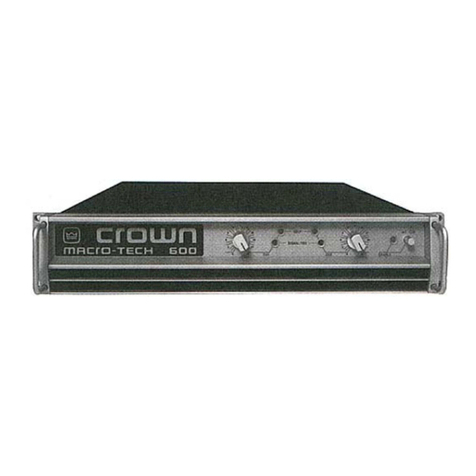
Crown Micro-Tech 1200 User manual

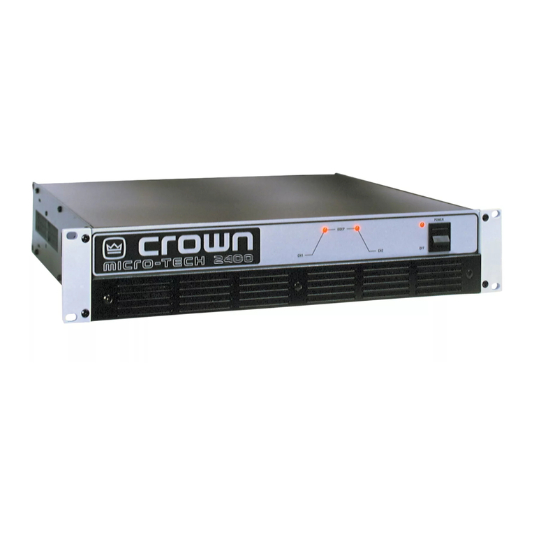
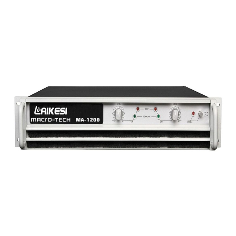
Micro-Tech 1200 Amplifier Service Manual
13
Electrical Checkout Procedures
GENERAL INFORMATION
The following test procedures are to be used to verify
operation of this amplifier. DO NOT connect a load or
inject a signal unless directed to do so by the proce-
dure. These tests, though meant for verification and
alignment of the amplifier, may also be very helpful in
troubleshooting. For best results, tests should be
performedinorder.
AlltestsassumethatACpowerisfromaregulated120
VACsource.Testequipmentincludesanoscilloscope,
a DMM, a signal generator, loads, and I.M.D. and
T.H.D. noise test equipment.
STANDARD INITIAL CONDITIONS
Level controls fully clockwise.
Stereo/MonoswitchinStereo.
Sensitivity switch in 26 dB fixed gain position.
It is assumed, in each step, that conditions of the
amplifier are per these initial conditions unless other-
wise specified.
TEST 1: DC OFFSET
Spec: 0 VDC, ±10 mV.
InitialConditions:Controlsperstandard,inputsshorted.
Procedure: Measure DC voltage at the output connec-
tors (rear panel). There is no adjustment for output
offset.Ifspecisnotmet,thereisanelectricalmalfunc-
tion.Slightlyoutofspecmeasurementisusuallydueto
U104/U204outoftolorance.
TEST 2: OUTPUT BIAS ADJUSTMENT
Spec: 300 to 320 mVDC.
InitialConditions:Controlsperstandard,heatsinktem-
peraturelessthan40°C.
Procedure:MeasureDCvoltagesontheoutputmodule
across R02, adjust R26 if necessary. Measure DC
voltagesontheoutputmoduleacrossR21,adjustR23
ifnecessary.Repeatforsecond channel.
TEST 3: ODEP VOLTAGE ADJUSTMENT
Spec: Bias Per Chart, ±0.1V DC.
Initial Conditions: Controls per standard, heatsink at
room temperature 20 to 30°C (68 to 86°F). Note: This
adjustment should normally be performed within 2
minutes of turn on from ambient (cold) conditions. If
possiblemeasureheatsinktemperature,ifnotmeasure
ambientroomtemperature.Usethisinformationwhen
referencingthefollowingchart.Thefollowingisalistof
ODEP bias voltages VS. temperature.
°F °C V–ODEP V+ODEP
66 18.9 –10.31 11.41
68 20.0 –10.26 11.36
70 21.1 –10.20 11.30
72 22.2 –10.14 11.24
74 23.3 –10.09 11.19
76 24.4 –10.03 11.13
77 25.0 –10.00 11.10
78 25.6 –9.97 11.07
80 26.7 –9.91 11.01
82 27.8 –9.86 10.96
84 28.9 –9.80 10.90
86 30.0 –9.74 10.84
88 31.1 –9.69 10.79
90 32.2 –9.63 10.73
92 33.3 –9.57 10.67
94 34.4 –9.51 10.61
–ODEPProcedure:Measurepin6ofU100and,ifneces-
sary, adjust R121 to obtain V–ODEP as specified above.
Measurepin6ofU200and, if necessary, adjust R221
to obtain V–ODEP as specified above.
+ODEPProcedure:Measurepin6ofU103and,ifneces-
sary, adjust R132 to obtain V+ODEP as specified above.
Measurepin6ofU203and, if necessary, adjust R232
to obtain V+ODEP as specified above.
Micro-Tech 1200 Amplifier Service Manual
14
TEST 4: AC POWER DRAW
Spec: 100 Watts maximum quiescent.
Initial Conditions: Controls per standard.
Procedure: With no input signal and no load, measure
AC line wattage draw. If current draw is excessive,
check for high AC line voltage or high bias voltage.
TEST 5: COMMON MODE REJECTION
Spec at 100 Hz: –70 dB.
Spec at 20 kHz: –50 dB.
Initial Conditions: Controls per standard.
Procedure: Noload. Inject a0dBu (.775VRMS) 100Hz
sinewaveintoeachchannel,onechannelatatime,with
invertingandnon-invertinginputsshortedtogether.At
the output measure less than –44 dBu (4.9mVRMS).
Injecta0dBu20kHzsinewaveintoeachchannel,one
channel at a time, with inverting and non-inverting
inputs shorted together. At the output measure less
than–24dBu(49mVRMS).ForMainModuleswithboard
numberslowerthanD7993-5adjustN100andN200to
calibrateCMR.ForMainModuleswithboardnumberD
7993-5orgreateradjustR921andR1021.
TEST 6: VOLTAGE GAIN
Spec 26dB Gain: Gain of 20.0 ±3%.
Spec 0.775V Sensitivity: ±6%.
Spec 1.4V Sensitivity: +12%/–6%.
Initial Conditions: Controls per standard.
Procedure:Noloadconnected.Injecta0.775VAC1kHz
sine wave with the Sensitivity Switch in the 26 dB
position.Measure15.5VAC±0.5 VAC at the amplifier
output. Inject a 0.775 VAC 1 kHz sine wave with the
SensitivitySwitchinthe0.775Vposition.Measure50.6
VAC±3VACattheamplifieroutput.Injecta1.4VAC1
kHz sine wave with the Sensitivity Switch in the 1.4V
position.Measure50.6VAC+6/–3VACattheamplifier
output. Return the Sensitivity Switch to the 26 dB
position.
TEST 7: PHASE RESPONSE
Spec: ±10° from 10 Hz to 20 kHz at 1 Watt.
InitialConditions:Controlsperstandard,8ohmloadon
eachchannel.
Procedure:Injecta1kHzsinewaveandadjustfor1Watt
output (2.8 VAC). Check input and output signals
against each other, input and output signals must be
within10° of each other.
TEST 8: LEVEL CONTROLS
Electrical Checkout Procedures
Spec: Level controlled by level controls.
Initial Conditions: Controls per standard.
Procedure:NoLoad.Injecta1kHzsinewave.Withlevel
controls fully clockwise you should see full gain. As
controlsarerotatedcounterclockwise,observesimilar
gainreductionineachchannel.Whencomplete,return
level controls to fully clockwise position.
TEST 9: CURRENT LIMIT
Spec: Current Limit at 30 Amps, ±2 Amps
Initial Conditions: Controls per standard.
Procedure:Loadeachchannelto1Ohm.Injecta1kHz
differentiated (or 10% duty cycle) square wave. See
figure4.Increaseoutputleveluntilcurrentlimitoccurs.
Current limit should occur at 30 ±2 Amps (30 Vpk).
Observeclean(nooscillations)currentclipping.
In Out
.047 uF
1K Ohm
Figure 4. Differentiator Circuit
TEST 10: SLEW RATE & 10 KHZ SQUARE WAVE
Spec: 13 - 15 V/µS.
Initial Conditions: Controls per standard.
Procedure:Loadeachchannelto8ohms.Injecta10kHz
square wave to obtain 65 volts zero-to-peak at each
output.Observetheslopeofthesquarewave.Itshould
typicallymeasure13to15V/µS.Also,thesquarewave
must not include overshoot, ringing, or any type of
oscillation.
TEST 11: CROSSTALK
Spec: -60dB at 20 kHz.
Initial Conditions: Controls per standard. Terminate
input of channel not driven with 600 ohms.
Procedure:8ohmloadoneachchannel.Injecta20kHz
sinewaveintotheChannel1inputandincreaseoutput
level to 33 VAC. Measure less than 33 mVAC at the
outputof Channel2. Injecta 20kHz sinewave intothe
Channel 2 input and increase output level to 33 VAC.
Measurelessthan33mVACattheoutputofChannel1.
TEST 12: OUTPUT POWER
Spec at 8 Ohm Stereo: >= 320W at 0.1% THD.
Micro-Tech 1200 Amplifier Service Manual
15
Electrical Checkout Procedures
Spec at 4 Ohm Stereo: >= 470W at 0.1% THD.
Spec at 2 Ohm Stereo: >= 600W at 0.1% THD.
International 8 Ohm Stereo: >=305W at 0.1% THD.
International 4 Ohm Stereo: >=430W at 0.1% THD.
International 2 Ohm Stereo: >=535W at 0.1% THD.
Initial Conditions: Controls per standard.
Procedure:Loadeachchannelto8ohms.Injecta1kHz
sinewaveandmeasureatleast50.60VACattheoutput
ofeachchannel.Loadeachchannelto4ohms.Injecta
1kHzsinewaveandmeasureatleast43.36VAC.Load
each channel to 2 ohms. Inject a 1 kHz sine wave and
measureatleast34.64VAC.Allpowermeasurements
must be at less than 0.1% THD.
TEST 13: REACTIVE LOADS
Spec: No oscillations. Safe with all types of loads.
Initial Conditions: Controls per standard.
Procedure Capacitive: Load each channel to 8 ohms in
parallelwith2µF.Injecta20kHzsinewavewith33VAC
output for 10 seconds.
Procedure Inductive: Load each channel to 8 ohms in
parallelwith159µHenries.Injecta1kHzsinewavewith
20 VAC output for 10 seconds.
Procedure Torture: Loadeachchannelwith theprimary
(redandblackleads)ofaDC-300Atransformer(D5781-
6).Inject a15 Hzsine waveat sufficientoutput levelto
cause 3 to 5 flyback pulses, for 10 seconds.
Procedure Short: Inject a 60 Hz sine wave at 20 VAC
output.Afterestablishingsignal,shorttheoutputfor10
seconds.
TEST 14: ODEP LIMITING
Spec:NooscillationonODEPLimitingwaveform;either
channelcontrols limitingin ParallelMonoMode.
Initial Conditions: Controls per standard; rag or other
obstruction blocking fan so that it does not turn.
Procedure: Load the amplifier to 2 ohms on each
channel.Injecta60Hzsinewaveandadjustfor20Vrms
attheoutput.Afterafewminutesobserveawaveform
similar to Figure 5. Remove the input signal from both
channels and allow the amplifier to cool for a few
minutes. Switch the amplifier to Parallel Mono and
remove the load from Channel 1. Inject the signal into
Channel1andobservethatODEPlimitingoccursatthe
outputofbothchannels.RemovetheloadfromChannel
2,andinstalltheloadonChannel1.Again,observethat
both channels limit. Return all amplifier controls to
standardinitialconditions.Removethefanobstruction.
TEST 15: LF PROTECTION
Spec: Amplifier mutes for low frequency.
Initial Conditions: Controls per standard.
Procedure:Noload.Inject a0.5 Hz6 voltpeak-to-peak
square wave, or a 2 Hz 6VAC sine wave into each
channelandverifythateachchannelcyclesintomute.
TEST 16: SIGNAL TO NOISE RATIO
Spec:100dBbelowrated8ohmpower20Hzto20kHz.
105 dB A-Weighted.
Initial Conditions: Controls per standard. Short inputs.
Procedure:Loadeachchannelto8ohms.Measureless
than506µVattheoutputofeachchannel(20Hz-20kHz
bandpassfilter).
TEST 17: TURN ON TRANSIENTS
Spec: No dangerous transients.
Initial Conditions: Controls per standard.
Procedure: From an off condition, turn on the amplifier
andmonitortheoutputnoiseatthetimeofturnon.Note:
Turnonnoisemayincreasesignificantlyiftheamplifier
is cycled off and on.
TEST 18: TURN OFF TRANSIENTS
Figure 5. ODEP Limiting Wave Form
Micro-Tech 1200 Amplifier Service Manual
16
Spec: No dangerous transients.
Initial Conditions: Controls per standard.
Procedure: From an on condition, turn off the amplifier
andmonitortheoutputnoiseatthetimeofturnoff.Note:
Turnoffnoisemayincreasesignificantlyiftheamplifier
is cycled off and on.
TEST 19: INTERMODULATION DISTORTION
Spec at 0 dB Output: 0.01%.
Spec at –35 dB Output: 0.05%.
Initial Conditions: Controls per standard.
Procedure: Load each channel to 8 ohms. Inject a
SMPTEstandardIMsignal(60Hzand7kHzsinewave
mixedat4:1ratio).Setthe60Hzportionofthesinewave
to38.9VoltRMS.Setthe 7kHzportionto25%.Withan
IManalyzermeasurelessthan0.01%IMD.Repeattest
at–35dB(reference38.9VoltRMS,60Hzportion)and
measure less than 0.05% IMD.
TEST 20: CLIPPING
Spec: No protective action during test.
Initial Conditions: Controls per standard.
Procedure:Loadeachchannelto8ohms.Injecta1kHz
sinewaveat eachinputanddriveoutput 6dBintoclip
for 10 seconds. The amplifier should not activate any
protectivecircuits(ODEP,Fault,orLF Protection).
POST TESTING
After completion of testing, if all tests are satisfactory,
the amplifier controls should be returned to the posi-
tionsrequiredbycustomer.Ifconditionsareunknown
or unspecified, factory settings are as follows:
Level Controls: 9 to 11 O’Clock.
Sensitivity Switch: 0.775V U.S., 1.4V International.
Stereo/MonoSwitch:Stereo.
Ground Lift: Lift.
Power:Off.
Electrical Checkout Procedures

Other manuals for Micro-Tech 1200

2

Other Crown Amplifier manuals

Crown XTi 2002 User manual

Crown

Crown XTi 2002 User manual

Crown XLS 802 User manual

Crown

Crown XLS 802 User manual

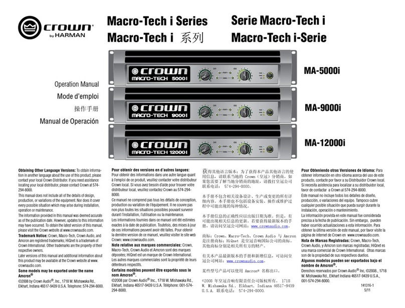
Crown MA-5000i User manual

Crown

Crown MA-5000i User manual

Crown XLS 602 User manual

Crown

Crown XLS 602 User manual

Crown XS1200 User manual

Crown

Crown XS1200 User manual

Crown CTs 2-Channel User manual

Crown

Crown CTs 2-Channel User manual

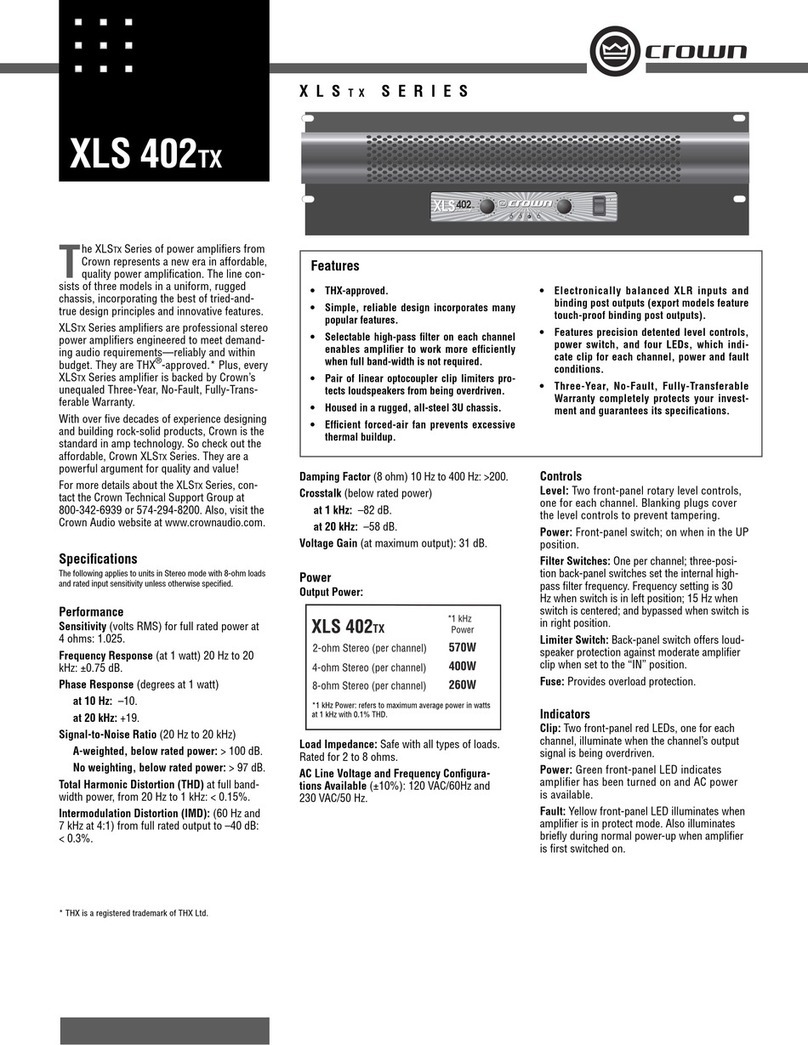
Crown XLS 402 User manual

Crown

Crown XLS 402 User manual

Crown XLS 202 User manual

Crown

Crown XLS 202 User manual

Crown Geodyne II User manual

Crown

Crown Geodyne II User manual

Crown PS-400 User manual

Crown

Crown PS-400 User manual

Crown M-600 User manual

Crown

Crown M-600 User manual

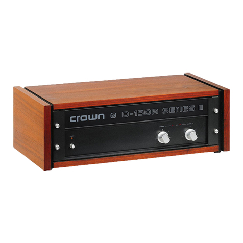
Crown D-150A Series II User manual

Crown

Crown D-150A Series II User manual

Crown Macro-Tech MA-5000VZ User manual

Crown

Crown Macro-Tech MA-5000VZ User manual

Crown Macro-Tech MA-24X6 User manual

Crown

Crown Macro-Tech MA-24X6 User manual

Crown CDi2 600 Installation and operating instructions

Crown

Crown CDi2 600 Installation and operating instructions

Crown Macro-Tech MA-3600VZ User manual

Crown

Crown Macro-Tech MA-3600VZ User manual

Crown Contractor Series User manual

Crown

Crown Contractor Series User manual

Crown PSA-2 User manual

Crown

Crown PSA-2 User manual

Crown DSi 1000 User manual

Crown

Crown DSi 1000 User manual

Crown I-Tech I-T8000 User manual

Crown

Crown I-Tech I-T8000 User manual

Crown LPS-800 User manual

Crown

Crown LPS-800 User manual

Crown SL-2 User manual

Crown

Crown SL-2 User manual

Crown CNi 4000 User manual

Crown

Crown CNi 4000 User manual

Crown XLS 1000 Series User manual

Crown

Crown XLS 1000 Series User manual

Popular Amplifier manuals by other brands

FONESTAR MPA-120 quick start guide

FONESTAR

FONESTAR MPA-120 quick start guide

Russound R290DS installation manual

Russound

Russound R290DS installation manual

Aquatic AQ-AD300.2 owner's manual

Aquatic

Aquatic AQ-AD300.2 owner's manual

ATI Audio DDA124-BNC Operating and maintenance manual

ATI Audio

ATI Audio DDA124-BNC Operating and maintenance manual

Rockford Fosgate POWER 150 Operation & installation

Rockford Fosgate

Rockford Fosgate POWER 150 Operation & installation

Electro-Voice High-Efficient, Lightweight Two-Channel Power Amplifier... Specification sheet

Electro-Voice

Electro-Voice High-Efficient, Lightweight Two-Channel Power Amplifier... Specification sheet

Yamaha PC4800N Service manual

Yamaha

Yamaha PC4800N Service manual

OEM 500 owner's manual

OEM

OEM 500 owner's manual

Takstar E5M quick start guide

Takstar

Takstar E5M quick start guide

FAME BVH300 owner's manual

FAME

FAME BVH300 owner's manual

B&G PT12060 owner's manual

B&G

B&G PT12060 owner's manual

EMPHASER EA2350 Installation & operating manual

EMPHASER

EMPHASER EA2350 Installation & operating manual

SCIENCE DECOLONIZER user manual

SCIENCE

SCIENCE DECOLONIZER user manual

moon 330A owner's manual

moon

moon 330A owner's manual

Sound Skulptor MP66 Setup guide

Sound Skulptor

Sound Skulptor MP66 Setup guide

NKT Koheras BOOSTIK user guide

NKT

NKT Koheras BOOSTIK user guide

Vivanco PA 115 operating instructions

Vivanco

Vivanco PA 115 operating instructions

RME Audio QuadMic user guide

RME Audio

RME Audio QuadMic user guide

manuals.online logo
manuals.online logoBrands
  • About & Mission
  • Contact us
  • Privacy Policy
  • Terms and Conditions

Copyright 2025 Manuals.Online. All Rights Reserved.