SST Modules
Page 4 Reference Manual
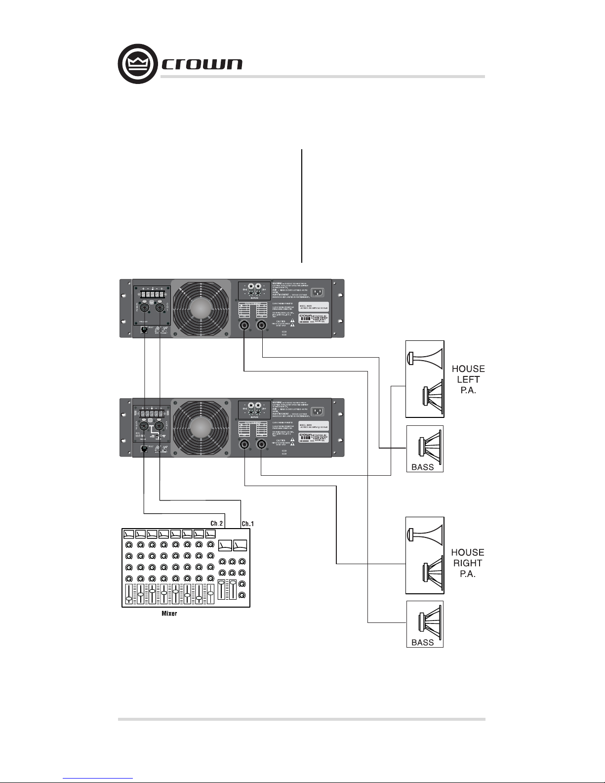
1 Welcome
Crown®’s System Solution Topology
(SST) modules bring you superior
control and flexibility with the con-
venience and cost savings of plug-in
processing. SSTs plug quickly and
easily into the back of your amp.
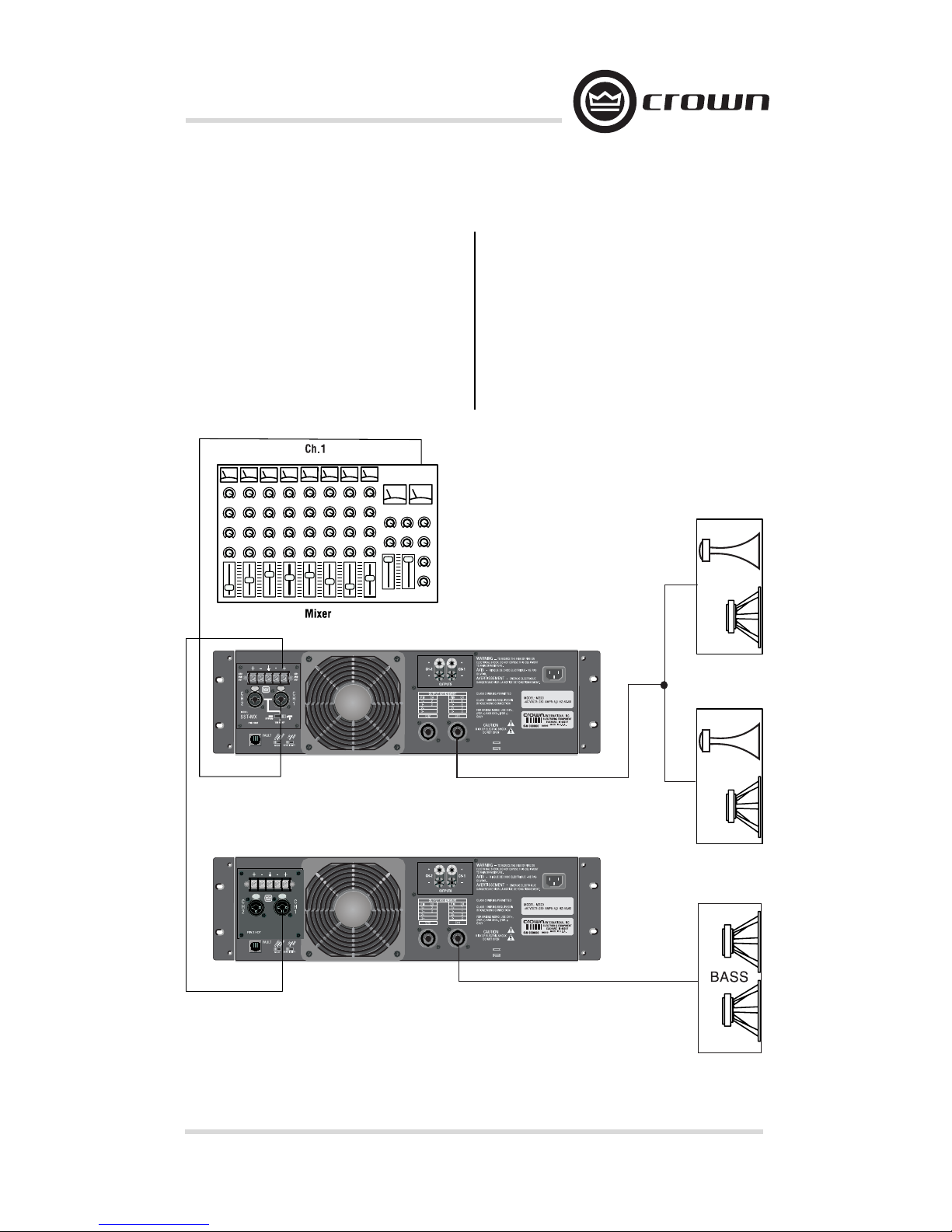
When you use a Crown SST module
to split the power drive to the
loudspeaker components, you gain
a wide range of advantages, includ-
ing:
1. Increased gain because the
insertion loss of passive cross-
over networks is eliminated.
2. Consistent power bandwidth:
power bandwidth is changed
in multi-way passive systems if
transducers change impedance
or vaporize (blow up).
3. Levels can be matched more
accurately to the components.
4. Quicker troubleshooting.
5. Improved dynamic range.
6. Better protection of components
due to steep 24-dB/octave filters.
With hard-wired precision compo-
nents, SST modules deliver consis-
tent bandwidth control, more accu-
rate level matching, and increased
gain (with none of the insertion
loss found with passive crossover
networks). Compact and versatile,
Crown SST modules continue the
Crown tradition for fast setup, great-
sounding output and exceptional
value.
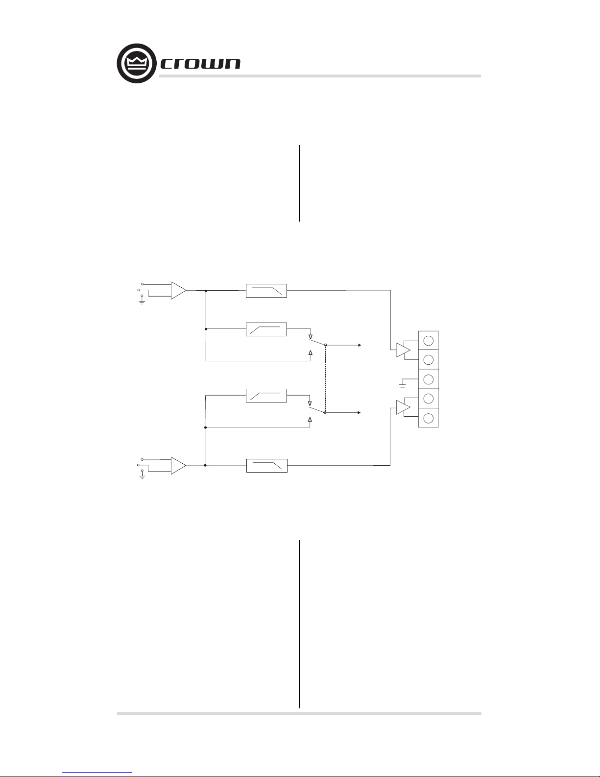
1.1 Wiring
All SST modules feature balanced
inputs. Some models also feature
balanced outputs for routing signals
to other amplifiers in biamped and
triamped systems.
Following are the standard wiring
conventions to follow when wiring
balanced connections to SST mod-
ules:
XLR (AES Standard)
Pin 1:
Pin 2: +
Pin 3: –
Tip Ring Sleeve
Tip: +
Ring: –
Sleeve:
Barrier Block and Terminal Block
connections should be wired as
marked on the SST front panel.