Crumar D9U User manual

DRAWBAR CONTROLLER D9U
An open-source Do-it-yourself
project base on Ar uino.
MOUNTING INSTRUCTIONS

Welcome to the mounting instruction sheet for the Crumar D9U Drawbar
Controller kit. To assemble this kit correctly an set it up to work
properly, a certain skill with electronics an computers is require , plus
some tools an a little bit of patience an attention.
REQUIRED TOOLS
1. Sol ering iron, preferably a temperature-controlle 60W iron with a
1,5 ~ 2,5 mm wi e tip;
2. Sol er, preferably goo quality 0,8 ~ 1 mm iameter;
3. Goo quality cutters;
4. Phillips screw river;
5. A computer with Ar uino IDE installe .
PREPARATION
Prepare a clean an ti y surface, with just the require tools han y an
make sure you have ischarge your bo y from electrostatic charge by
touching some metal object that makes contact with the floor. Optionally,
wear an ESD wristban .
WHAT'S IN THE KIT
- 1x PCB Drawbars v11_2018
- 1x PCB DB_CM_V11
- 1x Ar uino Pro Micro (Leonar o clone)
- 1x Metal bottom piece
- 1x Metal top cover
- 9x Drawbars
- 2x Brown Caps
- 3x Black Caps
- 4x White Caps
- 4x 220ohm 1/4W resistors
- 1x Re 3mm LED
- 1x Yellow 3mm LED
- 1x 2x8 DIL Strip
- 1x TRS 3.5mm Jack connector
- 1x Angle Tactile Switch
- 2x M3X12 Black screws
- 2x M3 Spacers
- 2x M3 Bolts
- 22x M3X4 Black screws
- 9x M3X6 screws
- 1x USB – MicroUSB cable
- 4x A hesive rubber feet

Electronic parts
Mechanical parts

STEP 1: Let's start from the electronics. All passive components, first,
starting from the lowest till the tallest. Take the four resistors, ben
the terminals 90 egrees an a them to the Main PCB as shown in the
pictures below.
Also a the LEDs, pay attention to the polarity an the posisions. The
shorter lea towar s the e ge of the boar , yellow on the right, re on
the left.
Procee with the sol ering of these first components an cut the excee ing
lea s.
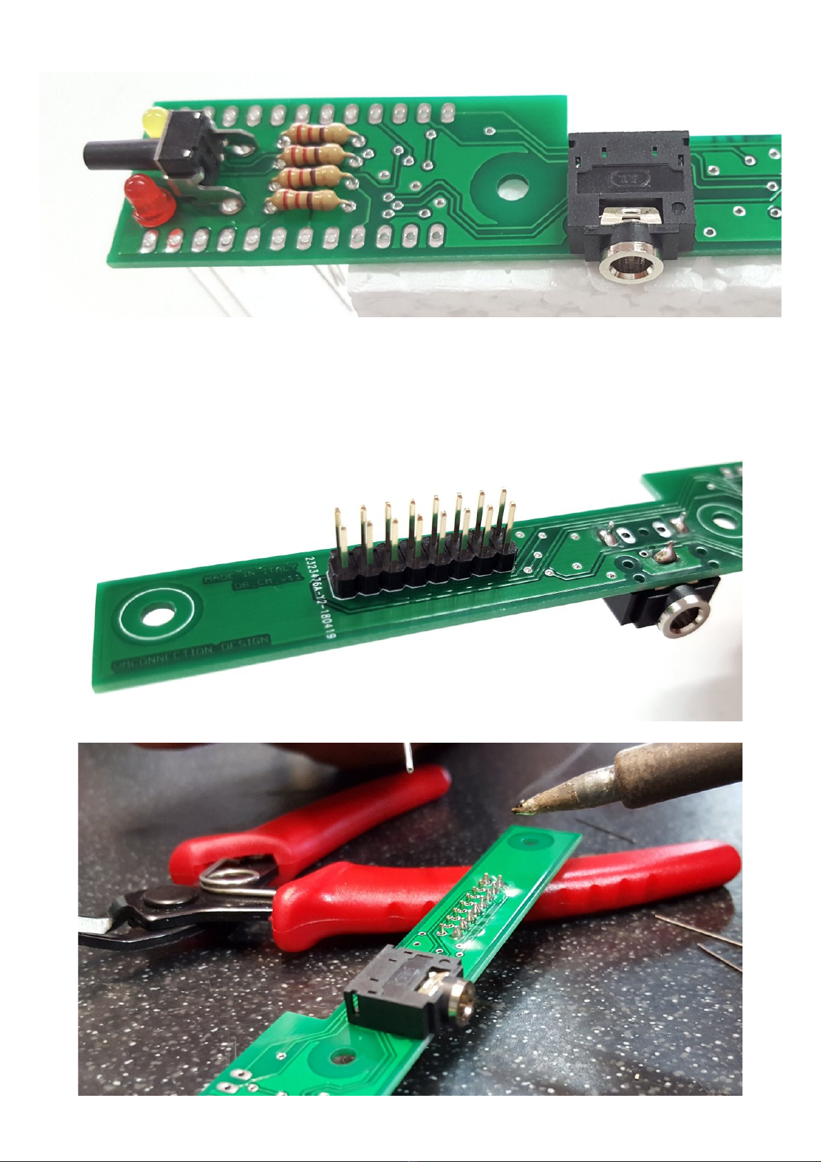
STEP 2: A the angle tactile switch an the mini TRS Jack.
STEP 3: turn the PCB upsi e own an a the 2x8 DIL strip, as shown in
the following picture. Pay attention to have it set straight on the boar
or you'll have troubles when coupling this boar with the rawbar boar .

STEP 4: Take the CPU boar an sol er the SIL terminals to the tiny boar .
This boar contains active SMT electronics an is subject to ESD an
overheat, make sure that your sol ering iron oesn't excee 350 °C
(~660°F) an on't keep the sol ering pin on the terminals for too long.
The SIL strip must face the bottom of the boar , thus the pins will be
sol ere on the top si e, as shown in the picture below.
STEP 5: A the CPU boar to the main boar , as shown in the following
picture. Make sure that the excee ing lea s from the resistors an the
LEDS have been cut as shortest as possible.

STEP 6: Once sol ere the CPU boar , the final assembly shoul look like
the picture below.
Now take your cutters an cut the excee ing terminal strip lea s on the
JACK si e, as shown below. Optionally, you can also cut the excee ing
lea s on the other si e.
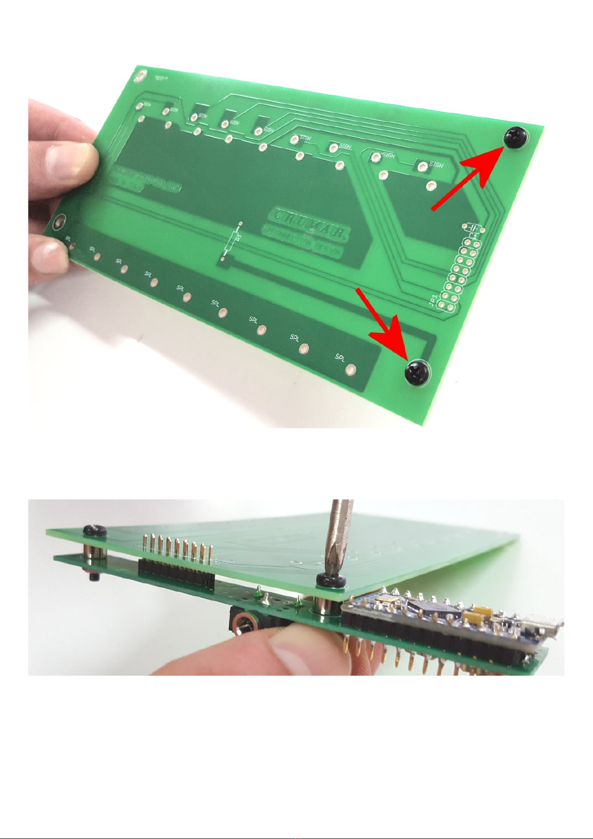
STEP 7: Couple the two boar s. The two M3X16 black screws must be set to
the right si e of the rawbar boar as shown here below.
Then, insert the spacers on the other si e, a the main boar an fix the
bolts using your fingers to hol the bolts an a screw river to tighten
the screws.
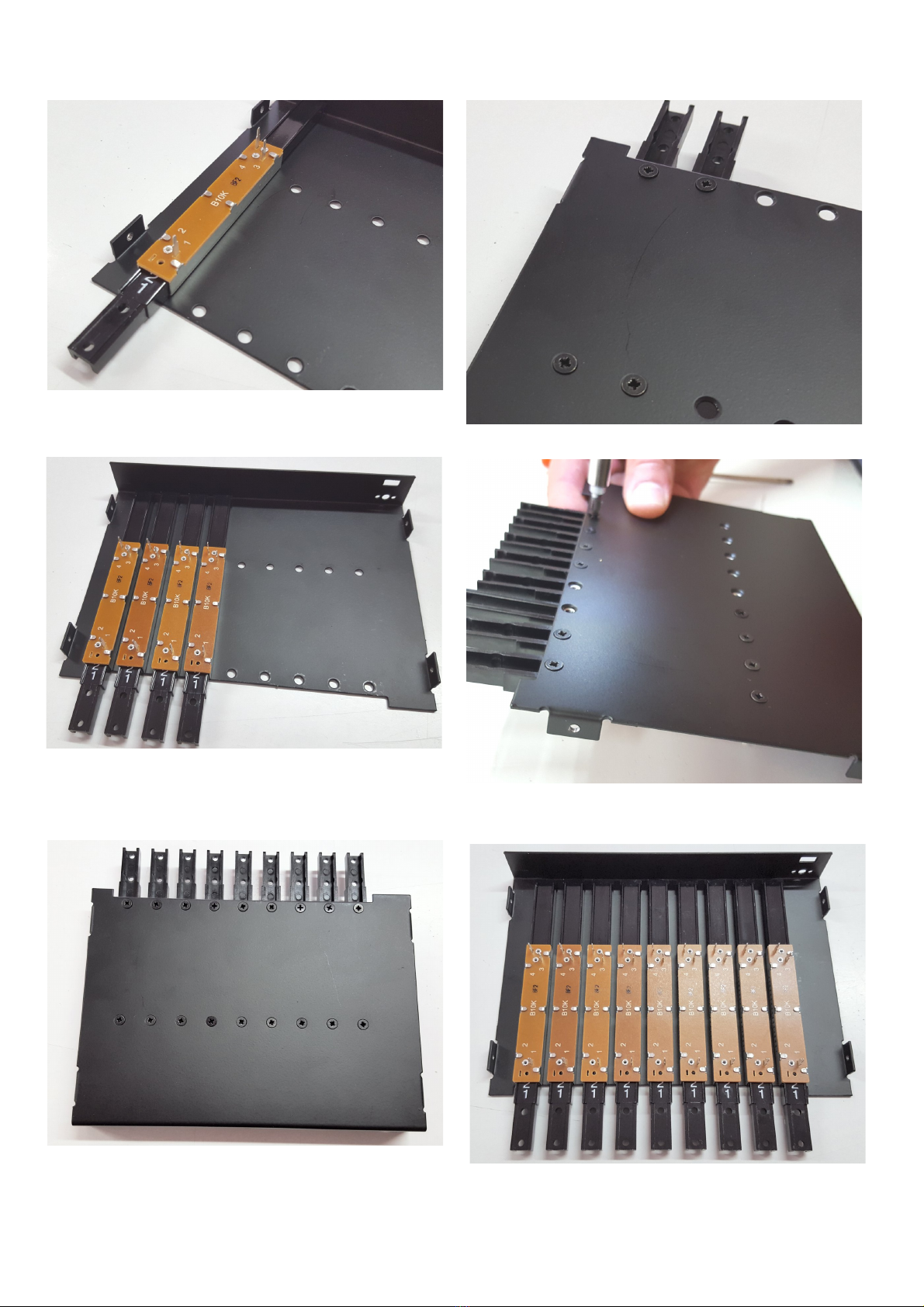
STEP 8: Use 18 out of the 22 M3X4 black screws to fix the rawbars to the
metal bottom piece, as shown in the picture sequence below.

STEP 9: Fix the PCB assembly to the rawbars an sol er the DIL terminals.
Sli e the boar s slighly angle so the MicroUSB connector can easily pass
through the hole in the metal panel.
STEP 10: Sol er all rawbar terminals an the DIL strip.

STEP 11: A the plastic rawbar caps. First set them in position using
the following color sequence:
BROWN – BROWN – WHITE – WHITE – BLACK – WHITE – BLACK – BLACK- WHITE
Once one, turn the whole assembly upsi e own an fix them using the 9
M3X6 screws.

STEP 12: Put the metal top cover. In or er to have the jack connector
easily pass through the hole in the metal panel, start from an angle from
the connector's si e.
Use the remaining 4 M3X4 screws to close the cover.

PROGRAMMING THE CPU WITH ARDUINO
You nee a computer with Ar uino IDE installe . Get the IDE from the URL
https://www.ar uino.cc/en/Main/Software an install it on your computer
following all the instructions given by the Ar uino ocumentation.
If you haven't ownloa e it yet, go to www.Crumar.it an ownloa the
Ar uino sketch for the D9U from the Support section.
Below the complete sketch listing with comments.
////////////////////////////////////////////////////////////////////
// Crumar Drawbar Controller D9U
// by Gui o Scognamiglio
// Runs on Atmel ATmega32U4 Ar uino Leonar o (with MIDI USB Library)
// Rea s 9 analog inputs from internal ADCs
// Sen s MIDI CC numbers 12-20 or 21-29 accor ing to selecte mo e
// Last up ate: July 2018
//
////////////////////////////////////////////////////////////////////
// This is where you can efine your CC numbers for the Bank 0 or 1
int CCMap[2][9] =
{
{ 12, 13, 14, 15, 16, 17, 18, 19, 20 }, // Upper rawbars
{ 21, 22, 23, 24, 25, 26, 27, 28, 29 } // Lower rawbars
};
////////////////////////////////////////////////////////////////////
// You shoul not mo ify anything else below this line
// unless you know what you're oing.
////////////////////////////////////////////////////////////////////
// Define I/O pins
# efine LED_RED 15
# efine LED_GREEN 16
# efine BUTTON 5
// Define global mo es
# efine DEBOUNCE_TIME 150
# efine DEADBAND 8
// Inclu e libraries
#inclu e <EEPROM.h>
#inclu e <MIDIUSB.h>
#inclu e <MIDI.h>
MIDI_CREATE_DEFAULT_INSTANCE();
// Init global variables
int mo e = 1; // Shoul be either 0 or 1
int prev_val[9] = { -1, -1, -1, -1, -1, -1, -1, -1, -1 };
int ebounce_timer = DEBOUNCE_TIME;
// ADC reference map
int ADCmap[9] = { A0, A1, A2, A3, A6, A7, A8, A9, A10 };
int ADCcnt = 0;

// Calle then the pushbutton is epresse
voi set_mo e()
{
igitalWrite(LED_RED, mo e ? LOW : HIGH);
igitalWrite(LED_GREEN, mo e ? HIGH : LOW);
EEPROM.write(0x01, mo e);
}
// Calle to generate the MIDI CC message
voi Sen Mi iCC(int channel, int num, int value)
{
mi iEventPacket_t CC = {0x0B, 0xB0 | channel, num, value};
Mi iUSB.sen MIDI(CC);
Mi iUSB.flush();
// Mi i lib wants channels 1~16
MIDI.sen ControlChange(num, value, channel+1);
}
// Calle to check whether a rawbar has been move
voi DoDrawbar(int , int value)
{
// Get ifference from current an previous value
int iff = abs(value - prev_val[ ]);
// Exit this function if the new value is not within the ea ban
if ( iff <= DEADBAND) return;
// Store new value
prev_val[ ] = value;
// Get the 7 bit value
int val7bit = value >> 3;
// Sen Mi i
Sen Mi iCC(mo e > 0 ? 1 : 0, CCMap[mo e][ ], val7bit);
}
// The setup routine runs once when you press reset:
voi setup()
{
// Initialize serial MIDI
MIDI.begin(MIDI_CHANNEL_OMNI);
// Set up igital I/Os
pinMo e(BUTTON, INPUT_PULLUP); // Button
pinMo e(LED_RED, OUTPUT); // Le 1
pinMo e(LED_GREEN, OUTPUT); // Le 2
// Recall mo e from memory an set
// Make sure mo e is either 0 or 1
mo e = EEPROM.rea (0x01) > 0 ? 1 : 0;
set_mo e();
}
// The loop routine runs over an over again forever:
voi loop()
{
// Rea analog inputs ( o the roun robin)
DoDrawbar(ADCcnt, analogRea (ADCmap[ADCcnt]));
if (++ADCcnt > 8) ADCcnt = 0;
// Rea Button
if ( igitalRea (BUTTON) == LOW)
{
if ( ebounce_timer > 0) -- ebounce_timer;
} else {
ebounce_timer = DEBOUNCE_TIME;
}
if ( ebounce_timer == 2)
{
mo e = !mo e; // Reverse
set_mo e(); // an Set!
}
}
PLEASE NOTE: before compiling the sketch, make sure you have installe the
require libraries (see next chapter).
Connect the D9U to your comptuer using the provi e USB cable, start the
IDE, loa the sketch, then:
1. From the TOOLS menu, select BOARD -> Ar uino Leonar o;
2. From the TOOLS menu, make sure the selecte PORT points to Leonar o;
3. Click the icon with the arrow pointing right, this will compile the
sketch an uploa it to the boar .
PLEASE NOTE: once the sketch is properly uploa e to the boar , the USB
port will not be seen by the IDE because it changes its function to USB-
MIDI. To check that it is actually seen as a MIDI evice, if you're using
Win ows (preferre ), ownloa an install the free application MIDI-OX an
check that the ARDUINO MIDI evice is liste among your MIDI ports, select
it as an input port to MIDI-OX an check that it is correctly sen ing the
expecte CC messages.
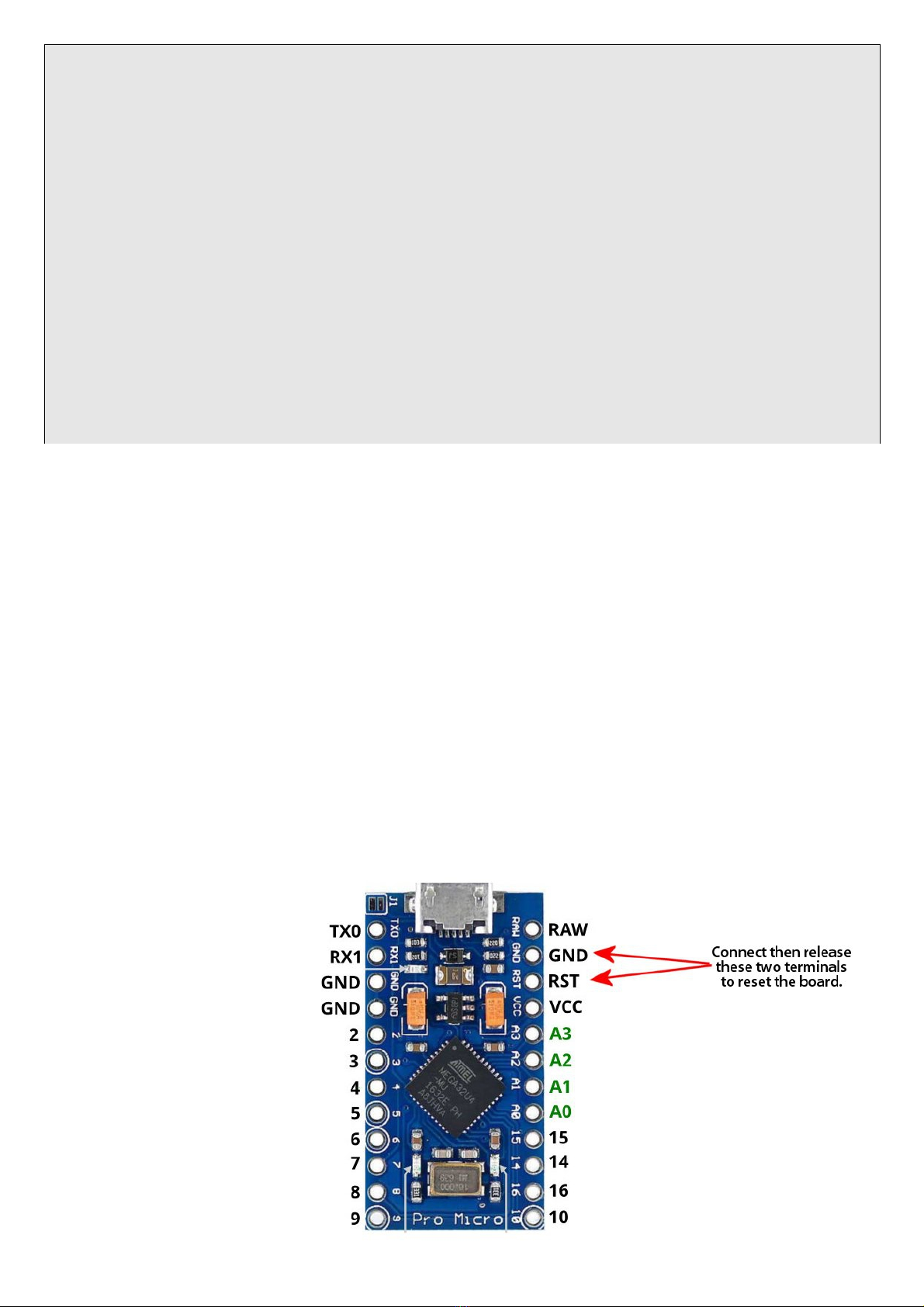
In case you nee to
reprogram the boar ,
one secon before
clicking the "LOAD"
icon in the Ar uino
IDE, you have to
"reset" the boar by
making a contact
between the terminals
labele RST an GND
using a small
screw river.

THE ARDUINO SKETCH EXPLAINED
The Atmel Atmega32U4 processor use on the Ar uino Leonar o (or Pro Micro)
boar has 9 built-in ADC inputs (Analog-to- igital converters), just what
we nee to rea 9 linear 10K potentiometers, that in our case are the
rawbars. All this sketch has to o is to rea the rawbars an generate
MIDI CC messages. Optionally, it can rea a push-button an lit 2 LEDs
that are use to swtich between two banks of pre- efine CC numbers, that
we can use to control either the Upper or the Lower manual of a Clonewheel
organ.
The MIDI stream is output both from the USB-MIDI port, using the 32u4
built-in USB controller, an from the UART port clocke at 31250 Bau as
the MIDI specs require.
So this sketch uses the following libraries (that shoul be installe
separately using the IDE library functions, in case they aren't pre-
installe ):
–MIDI Library by Fourty Seven Effects -
https://github.com/FortySevenEffects/ar uino_mi i_library Use to
generate MIDI messages to be sent to the UART PORT
–MIDIUSB by Gary Grewal - https://www.ar uino.cc/en/Reference/MIDIUSB
Use to generate MIDI messages to be sent via USB
–EEPROM (built-in) Use to store an recall the selecte CC bank into
the internal EEPROM
The loop() function cycles through the 9 ADCs by rea ing their current
values an storing them into an array; the same function also "listens"
whether the push button has been epresse (contact to groun , value LOW).
The pin to which the button is connecte has an internal pull-up resistor.
The DoDrawbar() function compares the value of a given ADC rea by loop()
with the previous value of the same ADC, if the ifference is greater than
the value set by DEADBAND, it is consi ere as a potentiometer value
change an generates the MIDI event to be sent. The DEADBAND value is set
to 8, because the ADCs have a 10 bit resolution (2^10 = 1024 values), but
we nee to scale it own to 7 bits (2^7 = 128 value), so we can iscar 7
values each 8. In other wor s, if previous value was 1000 an current is
1004, nothing changes, but if the new value is 1009, then this is
interprete as a value change. This mainly prevents unwante messages to
be sent when rawbars aren't actually move by the user.
The Sen Mi iCC() function generates the actual MIDI CC message, while
set_mo e() is calle each time the button is epresse , switches the LED,
sets the value of the "mo e" variable an stores it into the internal
EEPROM.
The CC numbers to be use are store into the two- imensional array
CCMap[2][9], which, as the numbers in the brackets suggest, contains 2
banks of 9 values each.
USING THE OPTIONAL SERIAL MIDI OUTPUT
The D9U can also be use with tra itional MIDI evices that use the common
DIN5 connector, but nee s a special "MiniJack to DIN5" a apter. This kin
of MIDI connection has become a stan ar in the recent years, but there
are two types. More informations can be foun on the MIDI.org website at
the following URL:
https://www.mi i.org/articles-ol /up ate -how-to-make-your-own-3-5mm-mini-
stereo-trs-to-mi i-5-pin- in-cables
The D9U uses TYPE B.
Use a 5V cellphone USB Charger/PSU to power the D9U an use your a apter
for the MIDI connection.
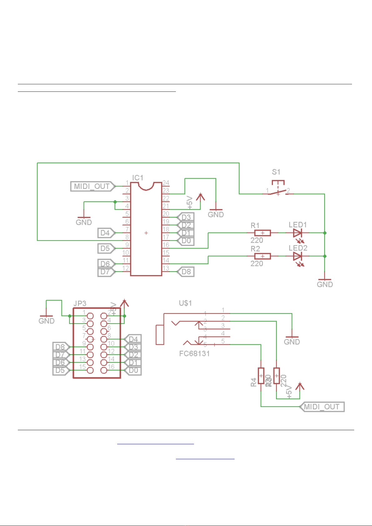
SCHEMATIC DIAGRAM
Crumar D9U is sol on www.MyRigShop.com by V.M.Connection
an enterprise base in Veneto, Italy.
For more informations please visit www.Crumar.it
Crumar is a registere tra emark.
All tra emarks mentione in this ocument belong to their respective
owners an are use for reference purposes only.
Table of contents
Other Crumar Music Equipment manuals


