Paia P9700S Installation guide

P9700S Overview
In a P9700S, the 9700K MIDI2CV8 is the power source for the other modu es in the kit. A separate power
supp y is not needed.
The wa -mount transformer for the 9700K is an ac power source which is converted to dc supp ies for the
circuits on the MIDI2CV8 and sent out to the other modu es via the four-circuit dc power connection points (a
rectangu ar area with a group of four so der areas (+) (G) (SG) (-).
The power connector kits in each of the pane accessories for the 9710, 9720 and 9730 have a four-pin header
and the wires, termina s, and cover for a 'pig-tai ' with the header p aced on the modu e to the eft for a daisy-
chained buss. The order of the modu es across the chassis is 9700 MIDI2CV8, 9720 VCO, 9730 VCF, and 9710
VCA. Notice there is a variation in the direction the header is insta ed on the 9700K (it faces opposite the way
the ones do on the other three modu es. The important thing is to get p us to p us, minus to minus, G to G, and
SG to SG.
The unregu ated dc supp ies from the 9700K are on-board regu ated to dua 12v supp ies on each of the VCO,
VCF, and VCA modu es.
( ) On page 17 of the MIDI2CV8 manua , for the step describing the preparation of the wa -mount transformer,
make a mark or note to put a rubber grommet over the wires before knotting them. This grommet is in the FR-7
chassis hardware package (and/or the 9700FRM package). This grommet wi s ot into the rear pane of the FR-
7 as the modu es are assemb ed into the chassis.
Patch Cords
When making the patch cord set, consider making one or two that are mu tip es, or ones with two or three wires
branching from one connector. This is particu ar y usefu for patches from the Gate-trigger output of the
MIDI2CV8.

MIDI2CV8 Pitch CV and VCO Scaling Adjustment (procedura supp ement)
Assert Low-key Transpose for 0V Pitch CV from the keyboard contro er ow key (reference the MIDI2CV8 kit
manua insert). This is the defau t, or automatic action with v3.0 firmware.
The DAC Tune trim is first set by connecting the pitch cv output to a mu titester set to measure dc vo ts in a 0-
10V range and then pressing octave spaced keys on the connected MIDI contro er whi e adjusting the trim for
1V changes.
Later the VCO wi be adjusted with this ca ibrated MIDI2CV8 output.
Whi e a tuner can be usefu , it can throw you off if the input is over oaded, c ipping the wave and introducing
harmonics. It is on y necessary to hear octaves as the adjustments are made.
The VCA L and R sections can be used to mix the VCO A and B and the output from the VCA L + R output for
monitoring.
Begin with the setting for a inear, vo t/octave pitch CV from the MIDI2CV8. A dvm can be used to check that
octave spaced key presses are outputting a 1V pitch cv change (down to a hundredth of a vo t or so) as set by the
trim on the MIDI2CV8. The most accurate setting wi be obtained if you press octaves that start a few notes
above the owest key, ie if your ow key is a C, press D or higher for the owest octave reading.
The usua tuned setting for the VCO sca e trims is about a 1:00 setting for the pointer of the disk which covers a
cw range from about 7:00 (ccw) to 5:00 (cw). Start with the trim at 1 o'c ock.
After having been powered for a minute or two patch the pitch CV over to the VCOA P2 input. Set the two
pitch contro s so they are both in-tune at unison at about a mid-rotation setting for the ow key pressed on the
contro er. P ay an octave higher and readjust the A pane pitch contro for an octave re ationship with B. Go
back to the ow note and adjust the A Sca e trim contro for unison and then, again, press an octave higher and
adjust the A pane Pitch contro for an octave re ationship with B. After going back and forth ike this another
time or two, you shou d find the sca e is about as c ose as is possib e. Then, do this a again pressing some note
a few keys higher than the owest key (with VCO B adjusted to match at this new ow pitch) and confirm/tweak
the sca e to match for higher pressed octave re ationships with B (using the A Sca e trim to rea ign A with B after
adjusting the A pane Pitch contro ). When the A Sca e adjustment is comp ete, move the pitch contro vo tage
over to VCO B P2 and make the pane Pitch and B Sca e trim adjustments to get unison and octaves referencing
the pitch of VCO A.
After the B Sca e trim is set, move the Pitch CV over to the VCOA P1 input and isten to the two vcos tracking
across the keyboard range after a igning their pitch whi e a higher note is pressed, say the third or fourth octave.
Confirm they track as you press keys going down towards the ow key. You shou d be ab e to turn up the sound
of the contro er or some other MIDI Sound Modu e and hear that the tones made from the VCOs can be a igned
using the pane pitch contro s and fo ow as you p ay different ranges on the keyboard (make the a ignment
between the two when a key pressed in the midd e C to A 440 range is pressed--its easier to hear the beating
s ow as they are tuned).

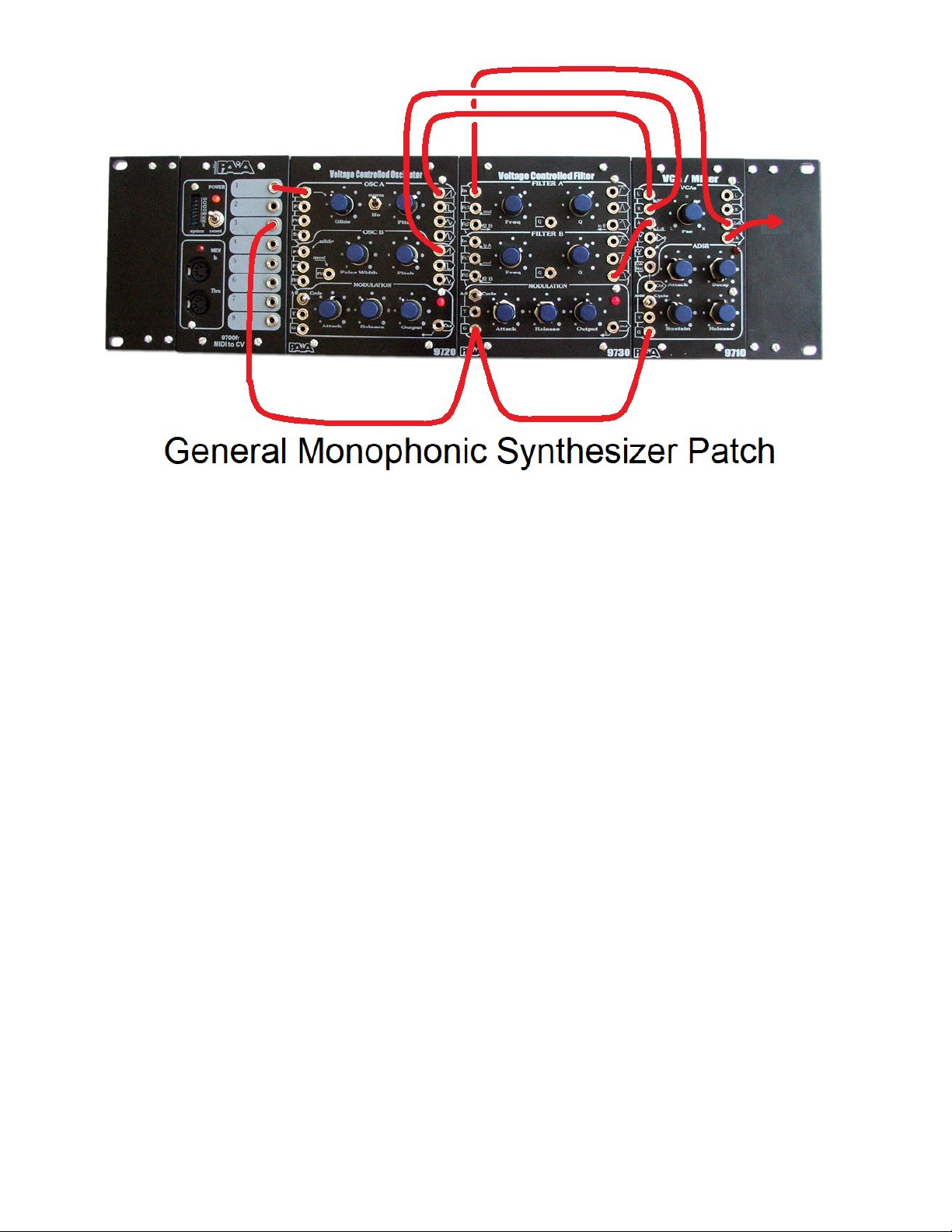
A general, monophonic synthesizer patch:
A common configuration is to start with the vc osci ators as the tone generator, to the L and R VCAs for a mix,
run through the vc fi ter for emphasis or de-emphasis of parts of that tone, and then through the vc amp ifier to
'frame' the sound. On the FatMan, two sawtooth (ramp) waves from the VCOs go to a LowPass VCF and then
to the VCA. Enve ope generators modu ate the VCF and VCA in response to the Gate trigger which indicates
the key pressed/re eased state. A Pitch CV amount according to the note pressed sets the VCO pitch.
A simp e way to imp ement this ead, mono synth patch on your P9700S is to make the fo owing connections
(patches). You may need to make some new cords a ong the way.
First, we' make the connections from the MIDI2CV8 operating in mode 1 for a mono voice comp ement of
outputs (power-up with the ow note pressed on the MIDI contro er and re ease it a coup e of seconds ater to
put the pitch cv in the best range). Use a sing e patch cord to go from the Pitch CV output on the MIDI2CV8 to
the P1 contro on VCO A. This a ows you to contro both osci ators and the G ide contro setting can be
adjusted to set the amount of time it takes for the osci ator frequency (pitch) to change for a Pitch CV change.
The Pitch contro of each osci ator can be adjusted so they are in unison or other re ationship (the rest of the
patch wi need to be made to hear this).
A 'Y' cord or one p ug with two wires and p ugs on it can be used to connect the Gate trigger output from the
MIDI2CV8 to the Gate trigger (G) inputs on the VCF and VCA modu es. This wi cause their enve ope
generator modu ators to start when a key is pressed.
Connect the two sawtooth waves from the VCOs to the L and R VCA inputs. The mix of the two waves is set
with the pan contro and the L+R output is the output of this mix and goes to VCF A In. We' take the output
from VCF B LowPass, or the bottom of the six connectors on the right-hand side with the graphic response
symbo s. Its best to keep the Q contro s at midway or so and the Frequency contro s s ight y different ti you
deve op a fee for the way the fi ter can accentuate or provide a boost on the signa . This boost can kick the
fi ter into osci ation or overdrive the VCA. The more the Q the more the boost, the ess the Q, the ess
'dramatic' the fi ter effect. The more simi ar the settings of the two series connected fi ters, the more critica the
Q setting. A cyc ic VCF modu ation is a neat effect too (instead of just an enve ope generator sweep in response
to the Gate). A Gate p us the cyc e setting gives a cyc e sync'ed to the key presses.
The VCA A section takes the VCF LowPass output with a sing e patch cord The VCA A output cou d patch to
a mixer or amp/speaker, etc.
The ADSR contro s set the dynamics of the sound as the keys are pressed and the enve ope is generated and
'opens' the VCA.
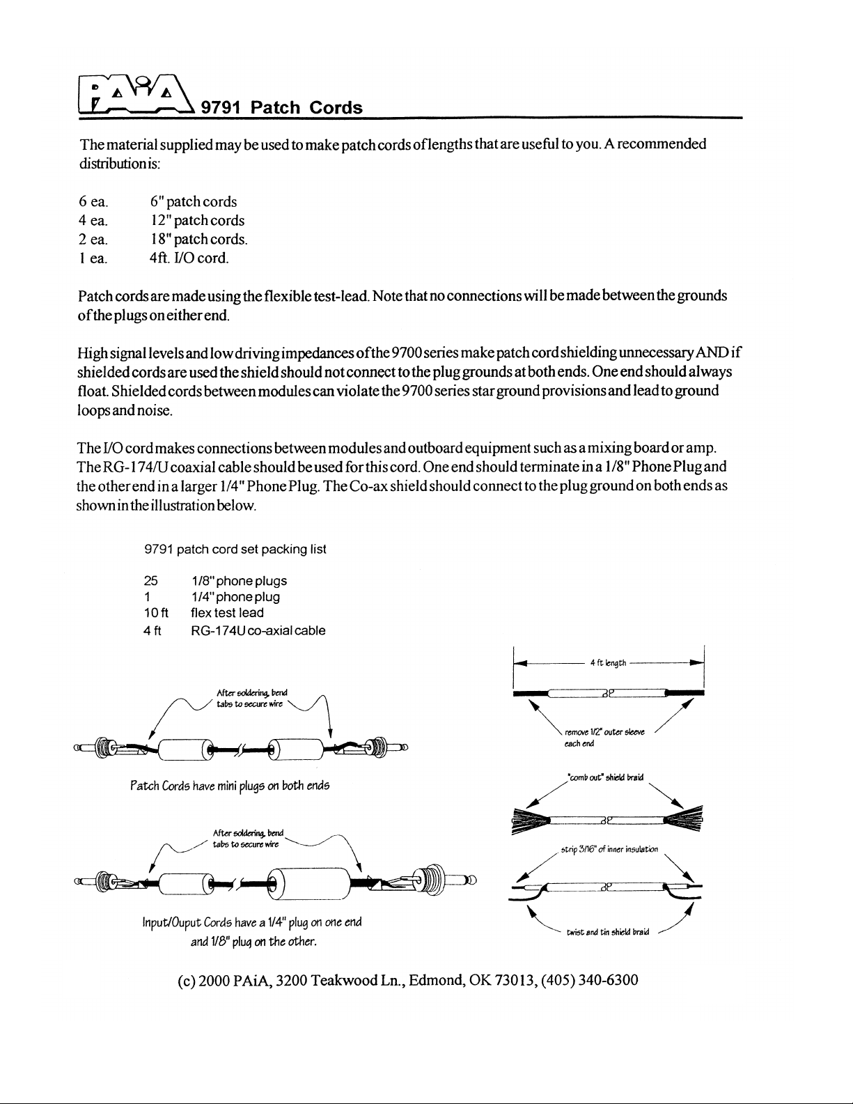
Note the VCO waveform outputs are high eve and you may need to set input eve s ower than for usua stuff,
or, a specia patch cord to attenuate the output can be made. I have one that puts a coup e of fixed resistors in
series from the tip to s eeve circuits on the p ug at 9700 end of the cab e and the signa is tapped at the junction
of the resistors for a more typica ' ine- eve '. The two resistors are a 10k and a 1k and the 10k attaches a the tip
and the 1k at the s eeve. The tap for the signa that wires on to the tip of the p ug for the mixer, amp/speaker, etc
is from the junction of the two resistors. The ground circuit is as usua --s eeve termina to s eeve termina . The
reason its needed here but not on modu e to modu e patches is that the modu es a share a ground a ready--the
power supp y ground circuit--but the synth and the externa device don't unti one connection is made between
them estab ishing a common ground.


FR7 Fractional Rack
(FracRak) Chassis
End pieces, module rails, and rack-mount ears bolt together with #4-4
machine screws and hex nuts – 1/2” black on front and 3/8” zinc on rear.
Top, bottom, and rear covers attach with
#4 x 1/4” sheet metal screws. The rear
has a slot for grommet / wire feed-thru
(typically on the rear, right-hand side).
FRModule / FRBlank panels attach to rails with
black #4 x 3/8” sheet metal screws.
Ten single-space panels (1.5” x 5.25”)
will fit in the 3U rack space.
Note: The end pieces have additional holes which may be used for pots, jacks, or other purposes as desired. Be aware that power connectors can have one
terminal common to the chassis and this can be a conflict when bringing in AC power where one wire is used as a neutral, circuit-common/ground. Remove
any finish protecting film before assembly. For best alignment, hand-tighten nuts and bolts until all in place, then fully tighten.

FR7 contents:
2 End Pieces
2 Rack Mount Ears
4 Mounting Rai s
8 4-40 x 1/2” Machine Screws, B ack (Front Pane /Rai s)
8 4-40 x 3/8” Machine Screws (Rear Rai s)
16 #4 Nuts
1 Instruction Sheet (This Document)
2 A uminum Cover P ates (1 Top and 1 Bottom)
1 A uminum Back P ate
24 #4 x 1/4” Sheet-meta Screws
1 Grommet, 1/4” (In Back P ate)
Sing e Pane #FRB-1 contents:
1 Sing e-wide Pane (1.5” x 5.25”)
2 #4 x 3/8” Sheet-meta Screws, B ack (Front Pane )
2 #4 ‘L’ Brackets
2 4-40 x 1/4” Machine Screws, B ack (Front Pane )
2 4-40 x 1/4” Machine Screws (Board to L Bracket)
2 #4 Nuts (Board to L Bracket)
Doub e Pane #FRB-2 contents:
1 Doub e-wide Pane (3.0” x 5.25”)
4 #4 x 3/8” Sheet-meta Screws, B ack (Front Pane )
2 #4 ‘L’ Brackets
2 4-40 x 1/4” Machine Screws, B ack (Front Pane )
2 4-40 x 1/4” Machine Screws (Board to L Bracket)
2 #4 Nuts (Board to L Bracket)
Trip e Pane #FRB-3 contents:
1 Trip e-wide Pane (4.5” x 5.25”)
4 #4 x 3/8” Sheet-meta Screws, B ack (Front Pane )
2 #4 ‘L’ Brackets
2 4-40 x 1/4” Machine Screws, B ack (Front Pane )
2 4-40 x 1/4” Machine Screws (Board to L Bracket)
2 #4 Nuts (Board to L Bracket)
Use threaded hole of L-Bracket
for mounting to FRBlank panel.

Table of contents
Other Paia Music Equipment manuals