CRYOMAGNETICS LM-510 Instruction Manual

LM-510 Operating Instruction Manual –Revision 1.3
1006 Alvin Weinberg Drive
Oak Ridge, Tennessee 37830
Phone: (865) 482-9551 Fax: (865) 483-1253
Web: http://www.cryomagnetics.com
WARNING!
DO NOT ATTEMPT TO OPERATE THIS EQUIPMENT BEFORE YOU
HAVE THOROUGHLY READ THIS INSTRUCTION MANUAL.
OPERATING INSTRUCTION MANUAL
FOR THE
MODEL LM-510
LIQUID CRYOGEN
LEVEL MONITOR


CE
MANUFACTURER'S DECLARATION OF CONFORMITY
According to lSO / IEC Guide 22 and EN45014
Manufacturer's Name: Cryomagnetics, Inc.
Manufacturer's Address: 1006 Alvin Weinberg Drive
Oak Ridge, TN 37830
Declares. the product
Product Name: Liquid Cryogen Level Monitor
Model Number: LM-510
Product Options: All Options
Conforms to the following Product Specifications:
Safety: EN61010-1 (95)
EN61326-1 (97)
EMC: EN61326-1 (97) Electrical Equipment for Measurement,
Control and Lab use –EMC Requirements
EN61000-4-2 (95) Electrostatic Discharge Immunity Test
EN61000-4-3 (96) Radiated Electromagnetic Fields
EN61000-4-4 (95) Electrical Fast Transient/Burst
EN61000-4-5 (95) Amendment A-Surge Immunity Test
EN61000-4-6 (96) Amendment A-Immunity to Conducted
Disturbances
EN61000-4-11 (94) Voltage Dips, Short Interruptions and
Voltage Variations
Application of Council Directives:
The product complies with the requirements of the Low Voltage Directive
73/23/EEC as amended by 93/68/EEC and the EMC Directive 89/336/EEC as
amended by 93/68/EEC.
D. Michael Coffey, President
Cryomagnetics, Inc
Oak Ridge Tennessee August 22, 2012


LM-510 Operating Instruction Manual –Revision 1.3
i
Table of Contents
1.0 Introduction ......................................................................................................... 1
2.0 Factory Calibrations, Installed Options and Certification ....................................... 5
3.0 Instrument Setup and Sensor Connection ............................................................. 7
3.1 Line Voltage and Fuse ..................................................................................................... 7
3.2 Connecting Sensors, Relay functions, and Analog Outputs ............................................... 7
4.0 Operation and Menus......................................................................................... 11
4.1 Menu Organization ....................................................................................................... 12
4.2 Liquid Helium Level Channel.......................................................................................... 14
4.2.1 Mode................................................................................................................................. 14
4.2.2 Alarm Set Points................................................................................................................ 14
4.2.3 Control Mode.................................................................................................................... 15
4.2.4 Units................................................................................................................................. 15
4.2.5 Boost................................................................................................................................. 15
4.2.6 Sensor Active Length......................................................................................................... 16
4.2.7 Lead Resistance................................................................................................................. 16
4.2.8 Ohms per CM .................................................................................................................... 16
4.3 Liquid Nitrogen (Capacitive) Level Channel .................................................................... 16
4.3.1 Alarm Set Points................................................................................................................ 17
4.3.2 Control Mode.................................................................................................................... 17
4.3.3 Units................................................................................................................................. 18
4.3.4 Sensor Active Length......................................................................................................... 18
4.3.5 Offset / Gain...................................................................................................................... 18
4.4 Setup Menu.................................................................................................................. 19
4.5 Advanced Menu –Firmware Updates and LN2 Sensor Configuration .............................. 20
4.5.1 LN2 Sensor Configuration ................................................................................................. 20
4.5.2 Firmware Update .............................................................................................................. 21
5.0 Control Interfacing ............................................................................................. 23
5.1 Analog Output .............................................................................................................. 23
5.2 Automatic Refill ............................................................................................................ 23
5.3 Using Ctrl as an Alarm ................................................................................................... 26
6.0 Theory of Operation ........................................................................................... 27
6.1 Liquid Helium Level Sensing (Superconductive Filament Probes) .................................... 27
6.2 Liquid Nitrogen Level Sensing (Capacitive Probes).......................................................... 28
6.3 LM-510 Circuit Description ............................................................................................ 29
7.0 Limited Warranty Policy ..................................................................................... 31
Appendix A - Computer Interface Command Reference................................................. 33
Appendix B - Line Voltage Controller Module –Option 4 ............................................... 52
Appendix C - Factory Calibration / Firmware Updates.................................................... 53
Liquid Helium Channels.............................................................................................................. 53

LM-510 Operating Instruction Manual –Revision 1.3
ii
Liquid Nitrogen Channels........................................................................................................... 53
Firmware Updates...................................................................................................................... 53
Appendix D –Updated LN2 Probe Notes....................................................................... 54
1. Calibrate empty level .................................................................................................... 54
2. Calibrate full level ......................................................................................................... 54
Appendix E - Helium Recondenser Controller Option..................................................... 55
List of Figures -
Figure 1 - LM-510 / Dual Channel LHe-LN2 ....................................................................................... 1
Figure 2 - LM-510 Rear Panel............................................................................................................. 7
Figure 3 - LHe Level Sensor Connector Wiring .................................................................................. 7
Figure 4 - LN2 Level Sensor Connector Wiring .................................................................................. 8
Figure 5 - Auxiliary Connector Wiring - DB-9F.................................................................................... 9
Figure 6 - Front Panel Display........................................................................................................... 11
Figure 7 - LM-510 Menu Hierarchy ................................................................................................... 13
Figure 8 - LHe Channel Menu...........................................................................................................14
Figure 9 - Liquid Nitrogen Channel Menu.........................................................................................17
Figure 10 - Setup Menu.....................................................................................................................19
Figure 11 - LN2 Sensor Configuration Menu .................................................................................... 20
Figure 12 - Firmware Update Menu ..................................................................................................21
Figure 13 - Typical Automatic Cryogen Refill System.......................................................................24

LM-510 Operating Instruction Manual –Revision 1.3
1
1.0 Introduction
The LM-510 Liquid Cryogen Level Monitor is the most advanced instrument for monitoring and
controlling cryogenic liquids available today. Its versatile architecture allows configuration to
virtually any cryogenic fluid including liquid helium, liquid nitrogen, LNG, LOX and many others.
Figure 1 - LM-510 / Dual Channel LHe-LN2
The LM-510 is available in single channel or two-channel versions. With the two-channel option the
instrument has two independent input channels that are factory configurable to either the same or
different liquid types. The unit is compatible with liquid helium level sensors based upon industry
standard niobium-titanium superconducting elements. Virtually all liquid helium sensor
manufacturers use this technology, so the LM-510 can be used with most existing equipment.
Flexible calibration procedures allow the use of two, three, or four wire configured liquid helium
sensors.
Capacitive sensors are used to monitor liquid nitrogen, LNG and other cryogenic fluids. As with
liquid helium sensors, the LM-510 can monitor many manufacturers’ capacitive sensors due to
advanced circuit design.
The LM-510 has user-adjustable high and low set points that may be used to control automated
refill cycles. With the two-channel option, independent set points can be adjusted for each channel.
This allows simultaneous control of two liquid cryogen systems with a single LM-510.
Also included are fully adjustable alarms for each channel. Most commonly set below the low
control set point, the alarm can be used to alert the user (audibly and visually) to a problem with the
refill cycle, and to automatically take action (relay contacts are provided).

LM-510 Operating Instruction Manual –Revision 1.3
2
Unique features of the LM-510 include a sensor deicing cycle and filament burnout protection for
liquid helium systems. This insures reliable, accurate level readings even under the most adverse
cryogenic conditions.
Computer control of the LM-510 is possible via USB and Ethernet interfaces –both are provided in
the standard configuration. IEEE-488 and RS-232 interfaces are available as options. LabVIEW®
virtual instrument drivers are available to allow computer control via a familiar, intuitive interface. A
wide variety of other options are also available that allow the instrument to be upgraded and tailored
to your particular requirements.

LM-510 Operating Instruction Manual –Revision 1.3
3
Specifications
Common Specifications
Display Update Rate: ~ 500ms Intervals
Control/ Alarm Relay Voltage Rating 100V
Control/ Alarm Relay Current Rating 135mA
12V Loop Source 25mA maximum
4-20mA Analog Output Loop Power 24V maximum
0-10V Analog Output 1 mA maximum
AC Input: 100-240V a.c., 50-60 Hz, 30 Watts
Operating Temperature: 15 C to 35 C
Relative Humidity 10% to 95%, non-condensing
Overall Dimensions: 185 mm W X 67 mm H X 197 mm D
Weight: 1.0 kg
USB interface: USB 1.1/2.0 Full-Speed
IEEE-488 interface: IEEE-488.2-1992 Standard
Ethernet: IEEE-802.3 10/100 BASE-T
Liquid Helium Channel Specifications
Maximum Sensor Length: 200 cm
Measurement Resolution 0.1 cm or 0.1 percent of sensor length
Measurement Accuracy +/- 0.5% FS
Liquid Nitrogen Channel Specifications
Maximum Sensor Capacitance: 2000 picofarads
Measurement Resolution 0.1 cm or 0.1 percent of sensor length
Measurement Accuracy +/- 1.0% of calibrated range
Model Configurations
LM-510-10 Single Channel Liquid Helium
LM-510-11 Dual Channel Liquid Helium
LM-510-20 Single Channel Liquid Nitrogen
LM-510-22 Dual Channel Liquid Nitrogen
LM-510-12 Dual Channel Liquid Helium/Liquid Nitrogen
Optional Equipment
LM-510-xx-1 IEEE-488 Interface
LM-510-xx-2 RS-232 Interface
LM-510-xx-3 19” Rack Mountable Cabinet
LM-510-xx-4 Line Voltage Controller Output
The LM-510 is designed to operate per the specifications in this table and the instructions provided in this
manual. Other use may impair the safety protections provided by the equipment.

LM-510 Operating Instruction Manual –Revision 1.3
4
This Page Intentionally Left Blank

LM-510 Operating Instruction Manual –Revision 1.3
5
2.0 Factory Calibrations, Installed Options and Certification
LM-510 Serial Number:
Input Channel 1:
Type: LHe LN2 Other:
Calibration: Sensor Manufacturer / Serial No:
Sensor Length:
Characteristic Resistance/Voltage:
Lead Resistance:
Input Channel 2: Not Installed:
Type: LHe LN2 Other:
Calibration: Sensor Manufacturer / Serial No:
Sensor Length:
Characteristic Resistance/Voltage:
Lead Resistance:
Computer Interface Installed: IEEE-488.2 (Option 1) : RS-232(Option 2):
Notes:
Certified:
Date:

LM-510 Operating Instruction Manual –Revision 1.3
6
This Page Intentionally Left Blank

LM-510 Operating Instruction Manual –Revision 1.3
7
3.0 Instrument Setup and Sensor Connection
The LM-510 is delivered to you fully tested and ready to operate. This includes sensor calibration if
Cryomagnetics supplied the sensor(s) with the instrument. Calibration will also be complete if the
active sensing length of an existing sensor(s) was specified at the time of order.
Figure 2 - LM-510 Rear Panel
3.1 Line Voltage and Fuse
The LM-510 is designed to operate with any AC power source between 100V and 240V A.C. and 50
to 60 Hz. No user serviceable fuse is provided.
3.2 Connecting Sensors, Relay functions, and Analog Outputs
Sensors connect to the LM-510 at the rear panel using circular connectors located above the labels
‘Channel 1’ and ‘Channel 2’. Figure 3 indicates the pin designations for the Liquid Helium Sensor
connectors.
(Rear LM-510 view)
Pin # Lead Function Teflon Color Phosphor-Bronze Color
1 I+Red Clear
2 V+Blue Yellow
3 Shield N/A N/A
4 V−Yellow Green
5 I−Black Black
Figure 3 - LHe Level Sensor Connector Wiring
1
2
3
4
5

LM-510 Operating Instruction Manual –Revision 1.3
8
The Liquid Nitrogen Level sensor connections are shown in Figure 4.
(Rear LM-510 view)
Pin # Lead Function Wire Color
1 V+ (10.6V) Red
2 Data White
3 Gnd Black
4 Shield N/A
Figure 4 - LN2 Level Sensor Connector Wiring
********** IMPORTANT ***********
1) Connections should NEVER be made directly to the connector on the rear panel. Always
solder to a mating connector that is not attached to the unit. Connections should be double-
checked for accuracy prior to attaching to the LM-510 and powering the unit ON since liquid
helium level sensors are driven by high voltages (up to 70 volts DC). These high voltages
could damage liquid nitrogen sensors or other sensors (such as temperature sensors or hall
probes) should these be accidentally connected.
2) NEVER connect/disconnect the sensors with the LM-510 powered ON.
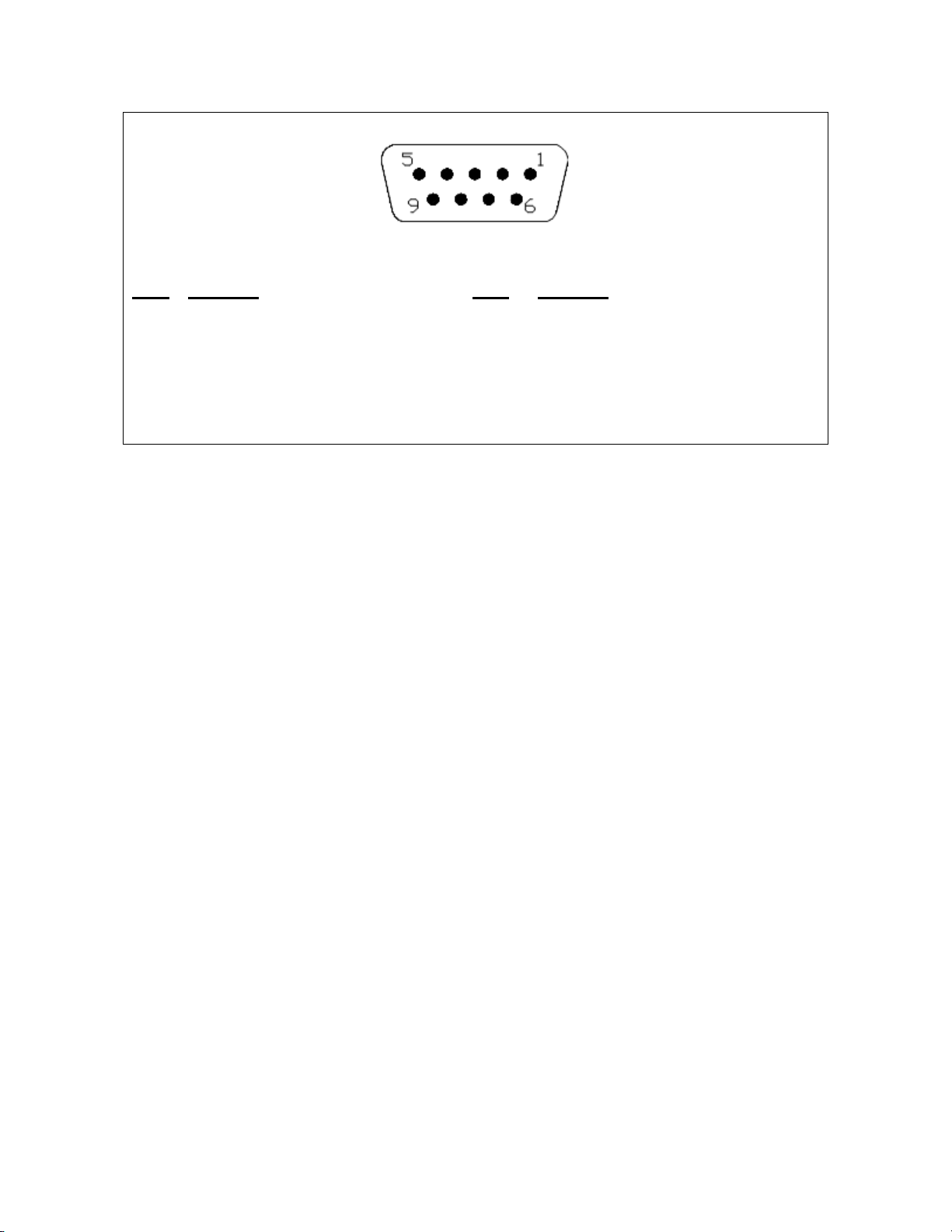
Each input channel of the LM-510 also has a dedicated auxiliary DB-9F connector. This connector
provides access to the automatic refill (control) relay and alarm relay functions, the 4-20mA analog
output signal, and the 0-10V analog output signal. There is also a 12V output that may be used to
power the 4-20mA analog output current loop. Figure 5 indicates the pin designations for the
auxiliary connector.
1
4
3
2
LM-510 Operating Instruction Manual –Revision 1.3
9
View Facing Rear Panel Connector
Pin # Function: Pin # Function:
1 Control Relay –Contact A (NO) 6 Control Relay –Contact B (NO)
2 Alarm Relay –Contact A (NO) 7 Alarm Relay –Contact B (NO)
3 0-10V Analog Output 8 4-20mA Loop Power In
4 4-20mA Analog Output 9 12V Loop Power Out (25mA max)
5 Analog Ground
Figure 5 - Auxiliary Connector Wiring - DB-9F
Cryomagnetics’liquid helium level sensors have four (4) lead wires and use either #30 AWG Teflon
insulated lead wires or color coded phosphor-bronze lead wires (either option may be specified
when the sensor is ordered). The connector pin connections and standard color codes for lead
wires are shown in Figure 3.
Some liquid helium level sensors made by Cryomagnetics may have only 2 or 3 lead wires. If the
sensor has 3 lead wires, the I- and V- leads are typically combined into a single black lead. If the
sensor has 2 lead wires, the I- and V- leads are combined into a single black lead and the V+ lead
is not used. The V+ connection at the input to the LM-510 should be connected to the I+ terminal in
this case.
Cabling between the liquid helium level sensor and the LM-510 should be of appropriate size such
that high voltage drop across the I+ and I- leads does not occur. It is recommended that cables up
to 5 meters in length be #18 AWG wire minimum. Cables from 5 to 15 meters in length should be
#16 AWG minimum, and cables from 15 to 30 meters should be #14 AWG minimum. Unshielded
cable may be used where no significant use of SCR-controlled equipment or intense electrostatic
field sources are present. Otherwise, it is recommended that shielded cable be used.

LM-510 Operating Instruction Manual –Revision 1.3
10
This Page Intentionally Left Blank

LM-510 Operating Instruction Manual –Revision 1.3
11
4.0 Operation and Menus
Setup of the LM-510 can be performed either through the front panel keypad and simple menu
instructions or through remote computer interface (USB, Ethernet or IEEE-488.2). Sensor set up
and calibration is only supported through the front panel keypad. The following sections contain
detailed descriptions of how to set up different sensor types and lengths, adjust alarms, and
configure the controller functions.
Before connecting any level sensors or other cabling to the LM-510, connect the power cord
provided with your LM-510 to an appropriate power source. Power the instrument ON and
familiarize yourself with the display. If your LM-510 is configured for dual sensor inputs, the top half
of the display will indicate Sensor #1 and the bottom half will indicate Sensor #2. If your LM-510 is
configured for a single sensor input, the display will only indicate one level.
Figure 6 - Front Panel Display
To the right of the liquid level reading is a bar-graph indication of liquid level. The bar-graph is color
coded to give a quick visual indication of system status.
The bar graph has two horizontal blue lines that indicate the automatic control set points that have
been entered. So for instance if you want to configure the LM-510 to automatically refill a cryostat
when the liquid level drops to 10% and turn off the fill when it reaches 90%, these values can be set
in the “Ctrl Low” and “Ctrl High” menu settings. Horizontal blue lines on the bar-graph show these

LM-510 Operating Instruction Manual –Revision 1.3
12
set points.
Similarly alarm high and low set points may be entered in the LM-510. These set points are shown
on the bar-graph with a red caret symbol. Setting the high alarm at 100% and the low alarm at 0%
removes the caret symbol from the display.
A liquid helium level channel may indicate "Open Sensor" or "Burnout Protect" instead of a level.
Open sensor is self-explanatory. If no sensor is attached to the LM-510 or if a connection is broken
the unit will display the error message and will disable the output to prevent high voltages from
being present on the sensor wires. If the LM-510 is in Continuous mode, the sensor will be
reactivated every 10 seconds to see if the connection has been fixed. If the LM-510 is in Sample-
and-Hold mode, the sensor will be reactivated at the normal sample interval.
Burnout Protect is displayed if the LM-510 detects a sensor resistance runaway condition (a
resistance more than 130% of the expected resistance of the sensor in gas and at room
temperature). This condition may occur if the user attempts to activate the sensor while it is in a
vacuum. Burnout protect is activated to reduce the chance of damaging the sensor. If Burnout
Protect is activated, the sensor will be deactivated and the error message displayed. As with Open
Sensor described above, if the LM-510 is in Continuous mode, the sensor will be reactivated every
30 seconds to see if the condition has been resolved. If the LM-510 is in Sample-and-Hold mode,
the sensor will be reactivated at the normal sample interval.
If the LM-510 is operating in sample/hold mode with a liquid helium level sensor, the top line of the
display will show a timer that indicates how long ago the displayed reading was taken. The interval
between readings may be adjusted (see section 4.2.1 below). If the user wants to update the
display without changing the sample interval, simply press <ENTER> and the instrument will take
new liquid helium level readings.
4.1 Menu Organization
The menus of the LM-510 are designed to minimize the number of keystrokes required, while at the
same time being intuitive for system operators. The level monitor menu options are accessed by
pressing the “Menu” button on the keypad and using the ◄► keys to highlight the desired channel
tab. General instrument setup options are accessed by highlighting the Setup tab.

LM-510 Operating Instruction Manual –Revision 1.3
13
Figure 7 - LM-510 Menu Hierarchy
Chan 1
(LHe Example)
Mode
•Continuous
•Sample/Hold
•Time Interval
•Disabled
Alarm Lo
Alarm Hi
Control Low
Control High
Control Mode
•Auto
•Manual
•Off
Timeout
Units
•Centimeters
•Inches
•Percent
Boost
•Off
•On
•Smart
Sensor Length
Lead Resistance
Ohms per CM
Chan 2
(LN2 Example)
Alarm Lo
Alarm Hi
Control Low
Control High
Control Mode
•Auto
•Manual
•Off
Timeout
Units
•Centimeters
•Inches
•Percent
Sensor Length
Zero Offset
Gain
Setup
Interface
•USB
•LAN
•GPIB
•RS-232
Baud Rate
GPIB ID
IP Address
Subnet
Gateway
MAC Address
Socket
Audio Alarm

LM-510 Operating Instruction Manual –Revision 1.3
14
4.2 Liquid Helium Level Channel
To set up a liquid helium level sensor, power ON the LM-510 and press the MENU key. Use the
◄► keys to select the appropriate sensor channel tab at the top of the display, then the ▲▼ keys
to select the sensor parameter to be calibrated. There are several user-adjustable options available
for liquid helium level monitoring. The above diagram indicates options and the menu headings
under which they are found. A description of the menu items is outlined below.
Figure 8 - LHe Channel Menu
4.2.1 Mode
In the Mode menu item the user can select Sample/Hold, Continuous or Off. This item appears first
in the menu list since it may be changed frequently in a system that is left in Sample/Hold mode
normally, but is switched to Continuous mode during liquid helium refills. Pressing ENTER while
“Mode” is selected toggles the unit between Sample/Hold, Continuous, and Off modes. The display
will indicate the selected mode.
While in Sample/Hold mode, an interval of time between readings of the liquid helium level sensor
in Sample/Hold mode can be specified. With Sample/Hold selected, press ►or ▼to highlight the
interval setting display. Then use the keypad keys to enter the sample interval to the desired time
in hours, minutes, and seconds, separating each with a “.” (decimal point).
4.2.2 Alarm Set Points
The LM-510 has alarm set points that may be used to alert the operator when the LHe level falls
Table of contents
Other CRYOMAGNETICS Measuring Instrument manuals


