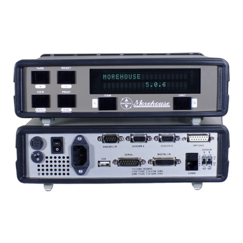
Morehouse C705P User manual

10/20/2022 Rev: 1
Instruction Manual PM-5947 Copyright © 2022
C705P Digital Indicator Meter
Instruction Manual

10/20/2022 Page 1 of 20 Rev: 1
Instruction Manual PM-5947 Copyright © 2022
Table of Contents
DISPLAY & KEYPAD DETAILS ........................................................................................ 2
INSTALLATION & OVERVIEW ......................................................................................... 4
Installation of C705P force data instrument .......................................................... 4
Power Connections (AC version) .......................................................................... 5
USB Port ............................................................................................................... 5
Getting Started ...................................................................................................... 5
SYSTEM CONFIGURATION ............................................................................................ 6
1.1 Configuration Menus ....................................................................................... 6
1.2 Entering the Setup (“F”) Configuration Menu .................................................. 7
1.3 Leaving the Setup (“F”) Configuration Menu ................................................... 7
1.4 Setup (“F”) Menu Descriptions ........................................................................ 8
1.5 Entering the Polynomial (“P”) Configuration Menu .......................................... 8
1.6 Leaving the Polynomial Setup (“P”) Configuration Menu ................................ 9
1.7 Polynomial Setup (“P”) Menu Descriptions ..................................................... 9
1.8 Entering the General (“G”) Configuration Menu ............................................ 10
1.9 Leaving the General (“G”) Configuration Menu ............................................. 11
1.10 General (“G”) Menu Descriptions ................................................................ 11
1.11 Entering the User/COM1 (“A1”) Menu ......................................................... 12
1.12 Leaving the User/COM1 (“A1”) Configuration Menu ................................... 13
1.13 User/COM1 (“A1”) Menu Descriptions ........................................................ 14
1.14 Entering the COM2 (“A2”) Menu ................................................................. 14
1.15 Leaving the COM2 (“A2”) Configuration Menu ............................................ 15
1.16 COM2 (“A2”) Menu Descriptions ................................................................. 15
INSTRUMENT CALIBRATION ........................................................................................ 16
2.1 Calibration Overview ..................................................................................... 16
2.2 Live Calibration Overview ............................................................................. 16
2.3 Live Span Calibration Instructions (PFx-F17) ................................................ 17
2.4 Live Negative Span Calibration Instructions (PFx-F15) ................................ 17
2.5 Live Calibration - Zero Instructions (PFx-F16) .............................................. 18
2.6 Entering B coefficient values for Compression Negative Span (PFx-CBx) ... 18
2.7 Entering B coefficient values for Tension Positive Span (PFx-TBx) .............. 18
2.8 Reference (mV/V) Calibration - Zero Instructions (G16) ............................... 19
2.9 Reference (mV/V) Calibration - Span Instructions (G17) .............................. 19
ADVANCED OPERATION .............................................................................................. 20
3.1 Peak Hold Mode ........................................................................................... 20
SERIAL PORT INFO ....................................................................................................... 20
OUTPUT STRINGS ........................................................................................................ 20

10/20/2022 Page 2 of 20 Rev: 1
Instruction Manual PM-5947 Copyright © 2022
DISPLAY & KEYPAD DETAILS
This instrument utilizes a 7-digit LCD (Liquid Crystal Display) with adjustable LED backlight.
The Table below summarizes the display annunciators:
Symbol
Display Indication
➔
0 Indicates that the instrument is in Tare mode.
P
Indicates that the instrument is in PEAK HOLD mode
T
The Tension mode shows "T"; The Compression mode shows " "
mV/V
Indicates that the unit of the displayed value is in millivolts per volt
Tf
Indicates that the unit of the displayed force is in tonne-force
klbf
Indicates that the unit of the displayed force is in kilopounds (kips)
lbf
Indicates that the unit of the displayed force is in pounds
kN
Indicates that the unit of the displayed force is in kilonewtons
N
Indicates that the unit of the displayed force is in Newtons
kgf
Indicates that the unit of the displayed force is in kilograms
This light is on whenever the instrument is at rest (i.e., a stable reading).

10/20/2022 Page 3 of 20 Rev: 1
Instruction Manual PM-5947 Copyright © 2022
The capacitive touch keypad is composed of a total of seven (7) function keys.
Marking
Keypad Functions
Menu/Off
This key provides access to the various configuration menus
(see System Configuration)
To turn the instrument OFF:
1. Press MENU/OFF key.
2. Press the PEAK/FREEZE button while “oFF?” is being displayed.
Units
Selects the displayed unit of measure:
Note:
If Primary Unit is lbf, kgf, or N , then avail. units are mV/V, lbf, kgf, and N
If Primary Unit is klbf, Tf, or kN , then avail. units are mV/V, klbf, Tf, and kN
Zero
The Zero key functions as a Tare ("->0<-" on display)
Peak/Freeze
Peak: Selects the peak hold display mode of the instrument, e.g., live data, positive
peak and negative peak.
Freeze:Pressing this key causes the display to stay constant (stop updating) until this
button is pressed again
Profile
Selects the one of the five available profiles [PF-1 to PF-5]; this action also takes the
instrument out of Tare mode.
Data
Sends the displayed data to the serial communication port.
On
Press and hold for 2-3 seconds to turn the unit ON.
SET &
arrows Utilized in the various configuration menus (see System Configuration)

10/20/2022 Page 4 of 20 Rev: 1
Instruction Manual PM-5947 Copyright © 2022
INSTALLATION & OVERVIEW
Remember that the installer is ultimately responsible to assure that an installation will be and
remain safe and operable under the specific conditions encountered.
Installation of C705P force data instrument
Find a suitable location for the instrument and use the included bracket to mount the unit to a wall or
table. Use this handy guide for mounting the bracket to a wall or table:
CONNECTIONS
The rear cover must first be removed to make the appropriate connections to the weigh platform, etc. To
remove the rear cover, simply remove the screws that secure it to the enclosure and set aside.
Caution! Disconnect power source from instrument prior to removing rear cover.
Caution! Disconnect leads from rechargeable battery (if installed) to avoid shorts!
Force sensor Connections
Connect your shielded force sensor cable to terminal block J1 using the table below. All terminals are
labeled for function.
TIP: You should have the color codes handy for your force sensor before doing so.
Force sensor Terminal Block J1

10/20/2022 Page 5 of 20 Rev: 1
Instruction Manual PM-5947 Copyright © 2022
Marking
Function
Marking
Function
GND
Shield
S-
- Signal
E+
+ Excitation
SE-
- Sense
SE+
+ Sense
E-
- Excitation
S+
+ Signal
NOTE1: Use G11 to configure for 4-wire or 6-wire force sensors
NOTE2: Pins 1 and 2 are for DC power input (V+ and V– respectively) …
NOTE3: There are two configurations for J1, as shown above, and differing only in the location of the
force sensor shield wire connection (GND)
Power Connections (AC version)
The C705P instrument ships with a pre-installed AC line cord. It has been pre-wired to Terminal Block J1
at the factory. Simply plug the unit into a standard wall outlet.
USB Port
The external USB port is used for communication and updating of the firmware. Consult factory for use.
Getting Started
1. Press and hold the ON key on the force instrument for two seconds.
After a brief initialization period, the instrument will revert to a zero (“0”) force display.
Your instrument is now ready for configuration and system calibration.

10/20/2022 Page 6 of 20 Rev: 1
Instruction Manual PM-5947 Copyright © 2022
SYSTEM CONFIGURATION
1.1 Configuration Menus
The C705P instrument contains five menus to configure the calibration system:
1. Setup (“F”) Menu –Configures all scaling parameters, including calibration procedures. All
Profiles [PF1-PF5]
2. Polynomial Setup (“P”) Menu –Configures all Polynomials. All Profiles [PF1-PF5]
3. General Setup (“G”) Menu –Configures general measurement parameters. Settings apply to all
Profiles [PF1-PF5]
4. User1 (“A1”) Menu –Configures COM1 communication parameters and other misc. parameters,
e.g., automatic turn off and hold mode.
5. User2 (“A2”) Menu –Configures COM2 communication parameters.
The configuration menus are laid out in the following vertical arrangement:
• Top [Menu selection] level [Note: some menus may have a secondary top level, e.g., -F- and F-
PF 1
• Parameter level
• Selection level (or function level, e.g., span calibration)
Please review the following chart to get a feel for how to navigate among the various menus and parameters.
NOTE: The -C- menu appears in place of the -B- menu for cabled systems.
Top
Level(s)
-F- \ F-PF 1
-G- \ G-
PF 1
-A1-
Parameter
Level
PF 1-F 1
PF 1-F
10
Etc.
PF 1-G3
PF 1-G8
Etc.
A1-1
A1-2
Etc.
Graduations
Decimal
Point
Zero
Band
Primary
Units
Baud Rate
Data &
Parity Bits
Selection
100 to
100 000
0, 0.0,
0.000,
0.0000
0, 1, 2,
5, 10,
20, 50,
100, 200
1, 2, 3,
4, 5, 6
1200, 2400,
4800, 9600,
19200,
38400,
57600,
115 200
8 n, 7 o, 7
E, 7 n
Level

10/20/2022 Page 7 of 20 Rev: 1
Instruction Manual PM-5947 Copyright © 2022
1.2 Entering the Setup (“F”) Configuration Menu
Note: This configuration menu has five (5) secondary-top levels - PF 1 to PF 5 - corresponding to the give
(5) profiles (PF-1 to PF-5). Instructions are identical for each profile.
1. Switch off the instrument by pressing the MENU/OFF key (“oFF”) followed by the PEAK/FREEZE
key.
2. Press and hold the ON key until the instrument beeps and starts to boot up.
3. During the countdown phase (“555555, 444444”, etc.) press and hold the MENU/OFF key until
the “Set?” message is displayed.
4. Press the PEAK/FREEZE button while “Set?” is being displayed. The instrument displays
“-F-“.
5. Scroll down one level by using the ZERO (down) key to reach the secondary top level. The
instrument shows “F-PF 1”.
6. Move from one profile [PF 1 to PF 5] to the next by using the PROFILE (left) or DATA (right) keys.
For example, to go from F-PF 1 to F-PF 2, press the DATA key. To go from F-PF 2 back to F-PF
1, press the PROFILE key.
7. Scroll down using the ZERO (down) key to reach the parameter level. The instrument shows
“PF1-F 1”.
8. Move from one “PF1-F” menu parameter to the next by using the PROFILE (left) or DATA (right)
keys. For example, to go from PF1-F 1 to PF1-F 10, press the DATA key. To go from F- PF1-F 10
back to PF1-F 1, press the PROFILE key.
9. Once you have arrived at the proper “PF1-F” menu parameter, e.g., “PF1-F 1”, press the
ZERO (down) key once to arrive at the selection level. The instrument displays the current
parameter setting.
10. If there is a selection list, scroll thru the available parameter settings, use the PROFILE (left) or
DATA (right) keys. Otherwise, use the arrow keys to adjust the displayed value to the new value.
11. Once the setting you want is displayed on the screen, press the PEAK/FREEZE (set) key to save
this value and revert up to the parameter level, e.g., “PF1-F 1”.
1.3 Leaving the Setup (“F”) Configuration Menu
1. While on any level except the selection level, press the MENU/OFF key.

10/20/2022 Page 8 of 20 Rev: 1
Instruction Manual PM-5947 Copyright © 2022
1.4 Setup (“F”) Menu Descriptions
This section provides more detailed descriptions of the selections found in the Setup Menu Chart.
The menus are identical for each profile (PF-1 to PF-5). Detailed instructions can be found in the next
section [Instrument Calibration]. Factory-set defaults are shown in bold with a checkmark; (√).
CODE/NAME
DESCRIPTION
SELECTION LIST
PF1-F1
Graduations
Sets the number of full-scale graduations, i.e., capacity ÷
division.
DO NOT CHANGE
Key-in
100 – 100 000
10000 √
PF1-F10
Decimal Point
Sets the decimal point value. Use together with PF1-F9.
0 √
0.0000 0.000
0.00 0.0
PF1-F15
Span Calibration -
Negative
Places instrument into live compression negative (-) span
calibration mode. Scrolling down with the ZERO key one
level begins the procedure.
Press ZERO key to begin
sequence
PF1-F16
Zero Calibration
Places instrument into live zero-calibration mode. Scrolling
down with the ZERO key one level begins the procedure.
Press ZERO key to begin
sequence
PF1-F17
Span Calibration -
Positive
Places instrument into live tension positive (+) span
calibration mode. Scrolling down with the ZERO key one
level begins the procedure.
Press ZERO key to begin
sequence
1.5 Entering the Polynomial (“P”) Configuration Menu
Note: This configuration menu has five (5) secondary-top levels - PF 1 to PF 5 - corresponding to the give
(5) profiles (PF-1 to PF-5). Instructions are identical for each profile.
1. Switch off the instrument by pressing the MENU/OFF key (“oFF”) followed by the PEAK/FREEZE
key.
2. Press and hold the ON key until the instrument beeps and starts to boot up.
3. During the countdown phase (“555555, 444444”, etc.) press and hold the MENU/OFF key until
the “Set?” message is displayed.
4. Press the PEAK/FREEZE button while “Set?” is being displayed. The instrument displays “-F-“.
5. Press the DATA (right) key once. The screen displays “-P-”.
6. Scroll down one level by using the ZERO (down) key to reach the secondary top level. The
instrument shows “P-PF 1”.
7. Move from one profile [PF 1 to PF 5] to the next by using the PROFILE (left) or DATA (right) keys.
For example, to go from P-PF 1 to P-PF 2, press the DATA key. To go from P-PF 2 back to P-PF
1, press the PROFILE key.

10/20/2022 Page 9 of 20 Rev: 1
Instruction Manual PM-5947 Copyright © 2022
8. Scroll down using the ZERO (down) key to reach the parameter level. The instrument shows
“PF1-Cb0”.
9. Move from one “PF1-” menu parameter to the next by using the PROFILE (left) or DATA (right)
keys. For example, to go from PF1-Cb0 to PF1-Cb1, press the DATA key. To go from PF1-Cb1
back to PF1-Cb0, press the PROFILE key.
10. Once you have arrived at the proper “PF1-” menu parameter, e.g., “PF1-Cb0”, press the
ZERO (down) key once to arrive at the selection level. The instrument displays the current
parameter setting.
11. If there is a selection list, scroll thru the available parameter settings, use the PROFILE (left) or
DATA (right) keys. Otherwise, use the arrow keys to adjust the displayed value to the new value.
12. Once the setting you want is displayed on the screen, press the PEAK/FREEZE (set) key to save
this value and revert up to the parameter level, e.g., “PF1-Cb0”.
1.6 Leaving the Polynomial Setup (“P”) Configuration Menu
1. While on any level except the selection level, press the MENU/OFF key.
1.7 Polynomial Setup (“P”) Menu Descriptions
This section provides more detailed descriptions of the selections found in the Polynomial Menu Chart.
The menus are identical for each profile (PF-1 to PF-5). Detailed instructions can be found in the next
section [Instrument Calibration]. Factory-set defaults are shown in bold with a checkmark; (√).
CODE/NAME
DESCRIPTION
SELECTION LIST
PF1-Cb0
Compression
(B0)
Sets the B0 polynomial term for compression negative span.
Scrolling down with the ZERO key one level begins the
procedure.
Press ZERO key to
begin sequence
PF1-Cb1
Compression
(B1)
Sets the B1 polynomial term for compression negative span.
Scrolling down with the ZERO key one level begins the
procedure.
Press ZERO key to
begin sequence
PF1-Cb2
Compression
(B2)
Sets the B2 polynomial term for compression negative span.
Scrolling down with the ZERO key one level begins the
procedure.
Press ZERO key to
begin sequence
PF1-Cb3
Compression
(B3)
Sets the B3 polynomial term for compression negative span.
Scrolling down with the ZERO key one level begins the
procedure.
Press ZERO key to
begin sequence

10/20/2022 Page 10 of 20 Rev: 1
Instruction Manual PM-5947 Copyright © 2022
PF1-tb0
Tension (B0)
Sets the B0 polynomial term for tension positive span.
Scrolling down with the ZERO key one level begins the
procedure.
Press ZERO key to
begin sequence
PF1-tb1
Tension (B1)
Sets the B1 polynomial term for tension positive span.
Scrolling down with the ZERO key one level begins the
procedure.
Press ZERO key to
begin sequence
PF1-tb2
Tension (B2)
Sets the B2 polynomial term for tension positive span.
Scrolling down with the ZERO key one level begins the
procedure.
Press ZERO key to
begin sequence
PF1-tb3
Tension (B3)
Sets the B3 polynomial term for tension positive span.
Scrolling down with the ZERO key one level begins the
procedure.
Press ZERO key to
begin sequence
1.8 Entering the General (“G”) Configuration Menu
Note: This configuration menu has five (5) secondary-top levels - PF 1 to PF 5 - corresponding to the give
(5) profiles (PF-1 to PF-5). Instructions are identical for each profile.
1. Switch off the instrument by pressing the MENU/OFF key (“oFF”) followed by the PEAK/FREEZE
key.
2. Press and hold the ON key until the instrument beeps and starts to boot up.
3. During the countdown phase (“555555, 444444”, etc.) press and hold the MENU/OFF key until
the “Set?” message is displayed.
4. Press the PEAK/FREEZE button while “Set?” is being displayed. The instrument displays
“-F-“.
5. Press the DATA (right) key twice. The screen displays “-G-”.
6. Scroll down one level by using the ZERO (down) key to reach the secondary top level. The
instrument shows “G-PF 1”.
7. Move from one profile [PF 1 to PF 5] to the next by using the PROFILE (left) or DATA (right) keys.
For example, to go from P-PF 1 to P-PF 2, press the DATA key. To go from P-PF 2 back to P-PF
1, press the PROFILE key. Note: Stay on this level to select G2 to G30 parameters.
8. Scroll down using the ZERO (down) key to reach the parameter level. The instrument shows
“PF1-G 3”.
9. Move from one “PF1-” menu parameter to the next by using the PROFILE (left) or DATA (right)
keys. For example, to go from PF1-G 3 to PF1-G 8, press the DATA key. To go from PF1-G 8
back to PF1-G 3, press the PROFILE key.

10/20/2022 Page 11 of 20 Rev: 1
Instruction Manual PM-5947 Copyright © 2022
10. Once you have arrived at the proper “PF1-” menu parameter, e.g., PF1-G 3”, press the
ZERO (down) key once to arrive at the selection level. The instrument displays the current
parameter setting.
13. If there is a selection list, scroll thru the available parameter settings, use the PROFILE (left) or
DATA (right) keys. Otherwise, use the arrow keys to adjust the displayed value to the new value.
14. Once the setting you want is displayed on the screen, press the PEAK/FREEZE (set) key to save
this value and revert up to the parameter level, e.g., “PF1-G 3”.
1.9 Leaving the General (“G”) Configuration Menu
1. While on any level except the selection level, press the MENU/OFF key
1.10 General (“G”) Menu Descriptions
This section provides more detailed descriptions of the selections found in the Setup Menu Chart.
These menus apply to all profiles (PF-1 to PF-5). Detailed instructions can be found in the next section
[Instrument Calibration]. Factory-set defaults are shown in bold with a checkmark; (√).
CODE/NAME
DESCRIPTION
SELECTION LIST
PF1-G3
Calibration
Equation
Switchover
Threshold
Selects the range within which the instrument will
automatically switch between tension and compression
modes.
"0" = 0.00000 mV/V "1 " =±0.00001 mV/V
"2" = ±0.00002 mV/V "5" = ±0.00005 mV/V
"10 = ±0.00010 mV/V "20" = ±0.00020 mV/V
"50" = ±0.00050 mV/V "100" = ±0.00100 mV/V
"200" = ±0.00200 mV/V
100 √
0, 1, 2, 5, 10, 20,
50, 100, 200
PF1-G8
Calibration Unit
Sets the force unit of measure to be used in the calibration
process and the default unit for normal operation.
"1" = pounds (lbf) "2 " = kilograms (kgf)
"3" = Newtons (N) "4" = kilopounds (kips)
"5" = Tonnes (Tf) “6" = kilonewtons (kN)
1 √ 2
3 4
5 6
PF1-G9
Display
Divisions
Sets the interval value. Use together with PF1-F10.
1 √
1, 2, 5, 10, 20, 50
PF1-G16
Zero Calibration
Places instrument into live zero-calibration mode. Scrolling
down with the ZERO key one level begins the procedure.
Press ZERO key
to begin sequence
PF1-G60
Mode
Used to select the primary source of system calibration.
“PoLYno” = Polynomials “LC-CAL” = Live Calibration
PoLYno √ LC-
CAL
G2
Sampling Rate
Sets the sampling rate in Hertz (measurements per second).
Note: H2 = Hertz (Hz)
10, 20, 30, 50, 60,
80, 120
10 H2√

10/20/2022 Page 12 of 20 Rev: 1
Instruction Manual PM-5947 Copyright © 2022
CODE/NAME
DESCRIPTION
SELECTION LIST
G6
Digital Filter
Averages force readings to produce higher stability. A lower
number provides a faster response. Choose the speed that
works best for your application.
"AUto" = Automatic “Avg-xx” = Averaging Filter
Auto √
01, 04, 08, 16, 24,
32, 40, 48, 56, 64
G11
No. of L/C wires
Selects the number of wires on the force sensor(s) to be
connected to the instrument. Cabled systems only.
"4" = four wires "6" = six wires (SENSE)
4 √ 6
G16
Ref. Calibration
- Zero
Places instrument into reference zero calibration mode
(mV/V). Scrolling down with the ZERO key one level begins
the procedure. Password protected – FACTORY USE ONLY!
Press ZERO key
to begin sequence
G17
Ref. Calibration
- Span
Places instrument into reference span calibration mode
(mV/V). Scrolling down with the ZERO key one level begins
the procedure. Password protected – FACTORY USE ONLY!
Press ZERO key
to begin sequence
G21
Factory Reset
This sub-menu will reset all setup parameters to the default
settings. It will not overwrite any previously saved calibration
data. Password protected – FACTORY USE ONLY!
Press the ZERO
key twice to
execute
G30
Special
Application
Used to select a special application feature.
“0” = None (Normal operation) “5” = Peak Operation
0 √ 5
1.11 Entering the User/COM1 (“A1”) Menu
1. Switch off the instrument by pressing the MENU/OFF key (“oFF”) followed by the PEAK/FREEZE
key.
2. Press and hold the ON key until the instrument beeps and starts to boot up.
3. During the countdown phase (“555555, 444444”, etc.) press and hold the MENU/OFF key until
the “Set?” message is displayed.
4. Press the PEAK/FREEZE button while “Set?” is being displayed. The instrument displays
“-F-“.
5. Press the DATA (right) key three times. The screen displays “-A1-”.
6. Scroll down using the ZERO (down) key to reach the parameter level. The force instrument
shows “A1-1”.
7. Move from one “A1” parameter to the next by using the PROFILE (left) or DATA (right) keys. For
example, to go from A1-1 to A1-2, press the DATA key. To go from A1-2 back to A1-1, press the
PROFILE key.

10/20/2022 Page 13 of 20 Rev: 1
Instruction Manual PM-5947 Copyright © 2022
8. Once you have arrived at the proper “A1” menu parameter, e.g., “A1-1”, press the
ZERO (down) key once to arrive at the selection level. The instrument displays the current
parameter setting.
9. If there is a selection list, scroll thru the available parameter settings, use the PROFILE (left) or
DATA (right) keys. Otherwise, use the arrow keys to adjust the displayed value to the new value.
10. Once the setting you want is displayed on the screen, press the PEAK/FREEZE (set) key to save
this value and revert up to the parameter level, e.g., “A1-1”.
1.12 Leaving the User/COM1 (“A1”) Configuration Menu
1. While on any level except the selection level, press the MENU/OFF key.
1.13 User/COM1 (“A1”) Menu Descriptions
This section provides more detailed descriptions of the selections found in the User/COM1 Menu Chart.
Factory-set defaults are shown in bold with a checkmark; (√).
CODE/NAME
DESCRIPTION
SELECTION LIST
A1-1
Baud Rate
Selects the baud rate for data transmission through the serial
port.
1200, 2400, 4800,
9600, 19200,
38400, 57600,
115200 √
A1-2
Data & Parity
Bits
Selects the number of data bits and parity of serial
transmission.
"8 n" = 8 data bits with no parity bit and one stop bit
"7 o" = 7 data bits with odd parity bit and one stop bit
"7 E" = 7 data bits with even parity bit and one stop bit
"7 n" = 7 data bits with no parity bit and two stop bits
8 n √
7 o
7 E
7 n
A1-24
Diagnostics
Used to access the listed test functions (one at a time).
Pressing the ZERO key begins the sequence.
"A1-24-1" = Display segment test, "A1-24-2" = A/D converter
test,
“A1-24-5” = Serial Port test (both), “A1-24-6” = Keyboard test
Press ZERO key to
begin sequence

10/20/2022 Page 14 of 20 Rev: 1
Instruction Manual PM-5947 Copyright © 2022
Diagnostics (A1-24)
Here is a brief description of each test mode:
A1-24-1 Display Test – Lights up all display segments. End test manually by pressing the
PEAK/FREEZE (Set) key.
A1-24-2 ADC Test – Shows internal A/D converter counts – useful for troubleshooting weighing issues.
End test manually by pressing the PEAK/FREEZE (Set) key. The Zero key works in this mode.
A1-24-5 Serial Test – Transmits a data string continuously out both serial ports (“TEST1” on COM1 and
“TEST2” on COM2). End test manually by pressing the PEAK/FREEZE (Set) key.
A1-24-6 Keyboard Test – Displays a keycode for each key pressed on the keypad. See Table below.
End test manually by pressing the PEAK/FREEZE (Set) key.
Key
Keycode
Menu/Off
12
Units
1
Zero
2
Peak
EXIT
Profile
4
Data
5
1.14 Entering the COM2 (“A2”) Menu
1. Switch off the instrument by pressing the MENU/OFF key (“oFF”) followed by the PEAK/FREEZE
key.
2. Press and hold the ON key until the instrument beeps and starts to boot up.
3. During the countdown phase (“555555, 444444”, etc.) press and hold the MENU/OFF key until
the “Set?” message is displayed.
4. Press the PEAK/FREEZE button while “Set?” is being displayed. The instrument displays
“-F-“.
5. Press the DATA (right) key four times. The screen displays “-A2-”.
6. Scroll down using the ZERO (down) key to reach the parameter level. The force instrument
shows “A2-1”.
7. Move from one “A2” parameter to the next by using the PROFILE (left) or DATA (right) keys. For
example, to go from A2-1 to A2-2, press the DATA key. To go from A2-2 back to A2-1, press the
PROFILE key.

10/20/2022 Page 15 of 20 Rev: 1
Instruction Manual PM-5947 Copyright © 2022
8. Once you have arrived at the proper “A2” menu parameter, e.g., “A2-1”, press the
ZERO (down) key once to arrive at the selection level. The instrument displays the current
parameter setting.
9. If there is a selection list, scroll thru the available parameter settings, use the PROFILE (left) or
DATA (right) keys. Otherwise, use the arrow keys to adjust the displayed value to the new value.
10. Once the setting you want is displayed on the screen, press the PEAK/FREEZE (set) key to save
this value and revert up to the parameter level, e.g., “A2-1”.
1.15 Leaving the COM2 (“A2”) Configuration Menu
1. While on any level except the selection level, press the MENU/OFF key.
1.16 COM2 (“A2”) Menu Descriptions
This section provides more detailed descriptions of the selections found in the COM2 Menu Chart.
Factory-set defaults are shown in bold with a checkmark; (√).
CODE/NAME
DESCRIPTION
SELECTION LIST
A2-1
Baud Rate
Selects the baud rate for data transmission
through the serial port.
1200, 2400, 4800, 9600,
19200, 38400, 57600, 115200
√
A2-2
Data & Parity Bits
Selects the number of data bits and parity of
serial transmission.
"8 n" = 8 data bits with no parity bit and one
stop bit
"7 o" = 7 data bits with odd parity bit and one
stop bit
"7 E" = 7 data bits with even parity bit and one
stop bit
"7 n" = 7 data bits with no parity bit and two
stop bits
8 n √
7 o
7 E
7 n
A2-6
Output String (Data
Format)
Selects the fixed output string for the COM2
serial port. Refer to Serial Port Info for details.
"0" = String Format 1 (Morehouse)
"1" = String Format 2 (Transcell)
0 √
1

10/20/2022 Page 16 of 20 Rev: 1
Instruction Manual PM-5947 Copyright © 2022
INSTRUMENT CALIBRATION
2.1 Calibration Overview
There are two ways to calibrate the instrument:
1. Live calibration: You will be calibrating an actual load sensor to the instrument using live test
loads. You can have up to seven positive calibration points and up to seven negative calibration
points. These calibration points are denoted as C1 through C7. The absolute value of each
subsequent calibration point should be higher than the last, e.g., the C2 value should be greater
than the C1 value, etc.
2. Polynomial Equations1: You will be entering B coefficients from a calibration report. You can enter
up to four positive B coefficients and up to four negative B coefficients. These B coefficients are
denoted as B0 through B3. This must be used in conjunction with a reference calibration using a
calibrator. See G16 and G17 for reference calibration instructions.
Note: to disable PFx-F15 or PFx-F17, simply enter a zero value (e.g., “0.0”) for C1.
2.2 Live Calibration Overview
Live calibration comprises two main steps: zero calibration (PFx-F16) and span calibration (PFx-F17).
However, a third calibration for negative span (PFx-F15) is also available for systems operating in both
tension and compression.
Here is the recommended sequence for multiple fixtures and multiple calibration points:
1. Put force sensor onto test fixture
2. Go to PFx-F17 and press the down key; indicator prompts for the first calibration point
3. key in number 111111 and press the PEAK key; indicator will show “FIT” momentarily and then
automatically record the fixture reference point
4. Follow the PFx-F17 procedure as written for up to seven calibration points
5. If necessary, repeat these steps for negative span calibration (PFx-F15)
6. Mount the force sensor onto the final fixture
7. Go to PFx-F16 and perform zero calibration
2.3 Live Span Calibration Instructions (PFx-F17)
1. While in the Setup mode, scroll to " PFx-F17 ", and then scroll down once using the
ZERO (down) key. The instrument will briefly display ‘C 1’ and then prompt you to enter the data
for the first calibration point (C1). The previously saved force value will be displayed with one digit
blinking.
1Force (lbf) = B₀+ B₁R + B₂R² + B₃R³

10/20/2022 Page 17 of 20 Rev: 1
Instruction Manual PM-5947 Copyright © 2022
2. Use the four directional keys to adjust the displayed value to 111111 and press the PEAK (set)
key; instrument will show “FIT” momentarily and then automatically record the fixture reference
point. The previously saved force value will be displayed with one digit blinking.
3. Place the first test load onto the force sensor.
4. Use the four directional keys to enter in the actual positive force value, e.g., 1000.0 lbf.
Increase the flashing digit by pressing the UNITS key. Decrease the flashing digit by pressing the
ZERO key. Pressing the PROFILE key or the DATA key will change the position of the flashing
digit.
5. Press the PEAK (set) key to save the value. The indicator briefly displays ‘End C1’ and then
moves to the next calibration point (C2).
6. Repeat steps 3 through 5 to enter data for the remainder of the calibration points. You need not
enter data for all seven calibration points. To cease entering additional calibration points,
simply enter zero for the new value, e.g., 0.0 lbf.
7. At the conclusion of C7 (or the last calibration point), the instrument will show “-donE” and reverts
to the top setup menu level, i.e.: “-F-”.
If the calibration was not successful, one of the following error messages will appear.
• "Err0" - The calibration test load or the keyed-in load is larger than the full capacity of the
instrument. Change the calibration test load or check the input data.
• "Err1" - The calibration test load or the keyed-in load is smaller than 1% of the full capacity of the
instrument. Change the calibration test load or check the input data.
• "Err2" – There is not enough signal from the force sensor to complete the calibration process.
Most common causes include incorrect force sensor wiring, a mechanical obstruction or a faulty
(damaged) force sensor.
Take the indicated action to correct the problem, and then perform a new calibration.
2.4 Live Negative Span Calibration Instructions (PFx-F15)
For negative calibration data, you will not see a minus sign on the screen. You need not be concerned as
all data entered is presumed to be a negative value, e.g., 1000.0 lbf is really
-1000.0 lbf.
1. While in the Setup mode, scroll to " PFx-F15", and then scroll down once using the
ZERO (down) key. The indicator will briefly display ‘C 1’ and then prompt you to enter the data for
the first calibration point (C1). The previously saved force value will be displayed with one digit
blinking.
2. Use the four directional keys to adjust the displayed value to 111111 and press the
PEAK (set) key; indicator will show “FIT” momentarily and then automatically record the fixture
reference point. The previously saved force value will be displayed with one digit blinking.
3. Place the first test load onto the force sensor.

10/20/2022 Page 18 of 20 Rev: 1
Instruction Manual PM-5947 Copyright © 2022
4. Use the four directional keys to the actual positive force value, e.g., 1000.0 lbf. Increase the
flashing digit by pressing the UNITS key. Decrease the flashing digit by pressing the ZERO key.
Pressing the PROFILE key or the DATA key will change the position of the flashing digit.
5. Press the PEAK (set) key to save the value. The indicator briefly displays ‘End C1’ and then
moves to the next negative calibration point (C2).
6. Repeat steps 3 through 5 to enter data for the remainder of the calibration points. You need not
enter data for all seven calibration points. To cease entering additional calibration points,
simply enter zero for the new value, e.g., 0.0 lbf.
7. At the conclusion of C7 (or the last calibration point), the instrument will show “-donE” and reverts
to the top setup menu level, i.e.: “-F-”.
2.5 Live Calibration - Zero Instructions (PFx-F16)
1. While in the Setup mode, scroll to " PFx-F16", and then scroll down once using the
ZERO (down) key. The display will momentarily show "C 0" followed by a value. This value is the
internal A/D count and can prove useful when trying to troubleshoot setup problems.
2. Mount the force sensor onto the final fixture, assure a no-load condition and then press the PEAK
(set) key to save the zero-point value. The display will show “SET” and "EndC0" momentarily,
and then revert up to PFx-F16.
2.6 Entering B coefficient values for Compression Negative Span (PFx-CBx)
The B coefficient values for Compression Negative Span are entered one at a time in the “P” menu, using
two separate screens (pages). This example sets CB0 [B0 Compression Negative Span] to -
1.210034E+03 using the PF1-CB0 menu. All other menus [PF1-CB1, PF1-CB2 and PF1-CB3] operate
the same way.
Example: B0 = -1.210034E+03,
Page1: [1].[2][1][0][0][3][4] (B coefficient value)
Page2: [- ] [ ][ ] [E][P][0][3] (sign convention and exponent)
1. While in the Setup mode, scroll to " PF1-CB0 ", and then scroll down once using the
ZERO (down) key. The instrument will briefly display ‘1 of 2’ and then prompt you to enter the B
coefficient value. The previously saved B coefficient value will be displayed with one digit blinking.
2. Use the four directional keys to adjust the displayed value to the proper B0 coefficient value and
press the PEAK (set) key. The instrument will briefly display ‘2 of 2’ and then prompt you to enter
the sign convention and exponent value. The previously saved sign convention and exponent
value will be displayed with one digit blinking.
3. Use the four directional keys to adjust the displayed value to the proper sign convention and
exponent value and press the PEAK (set) key. The instrument will briefly display ‘SET’ and revert
to the PF1-CB0 menu level.
4. Repeat steps 1 through 3 as needed for the other Compression Negative Span B coefficient
values.

10/20/2022 Page 19 of 20 Rev: 1
Instruction Manual PM-5947 Copyright © 2022
2.7 Entering B coefficient values for Tension Positive Span (PFx-TBx)
Same as previous section, only using the PF1-TB0, PF1-TB1, PF1-TB2 and PF1-TB3 menus.
2.8 Reference (mV/V) Calibration - Zero Instructions (G16)
You will be teaching your instrument the 0.0 mV/V setting of your calibrator. (C0)
1. While in the Setup mode, scroll to " G16 ", and then scroll down once using the
ZERO (down) key. The instrument will briefly display ‘Code ? and then prompt you to enter the
password. Six zeros are now displayed with one blinking.
2. Use the four directional keys to adjust the displayed value to the password and press the PEAK
(set) key. The display will momentarily show "C 0" followed by a value. This value is the internal
A/D count and can prove useful when trying to troubleshoot setup problems.
3. Move your calibrator to the 0.0 mV/V setting and press the PEAK (set) key. The instrument will
briefly display ‘SET’ and revert to the G16 menu level.
2.9 Reference (mV/V) Calibration - Span Instructions (G17)
You will be teaching your instrument the mV/V setting of your choice using your calibrator. (C1)
1. While in the Setup mode, scroll to " G17 ", and then scroll down once using the
ZERO (down) key. The instrument will briefly display ‘Code ?’ and then prompt you to enter the
password. Six zeros are now displayed with one blinking.
2. Use the four directional keys to adjust the displayed value to the password and press the PEAK
(set) key. The display will momentarily show "C 1" followed by Six zeros with one blinking.
3. Use the four directional keys to adjust the displayed value to the mV/V setting of your choice,
e.g., 2.00000.
4. Move your calibrator to the mV/V setting of your choice and press the PEAK (set) key. The
instrument will briefly display ‘SET’ and revert to the G17 menu level.
ADVANCED OPERATION
3.1 Peak Hold Mode
This mode is used to capture and hold peak forces recorded during a specific process. The most common
application is evaluating the breaking point of a part or assembly. The instrument records both positive
and negative peak forces.
This mode of operation is enabled by changing the F30 parameter setting to “5”.
1. Push the PEAK key to activate positive peak mode; the instrument briefly displays “HoLd P” and
then the “P” annunciator turns ON.
2. Apply force to the item under test. The display indicates and holds the positive peak force
applied.
Table of contents
Other Morehouse Measuring Instrument manuals
Popular Measuring Instrument manuals by other brands

Agilent Technologies
Agilent Technologies 4155C user guide

ProfiTap
ProfiTap ProfiShark 10G Installation and configuration manual

Badger Meter
Badger Meter Hedland EZ-View quick guide

Video Clarity
Video Clarity ClearView installation guide

Cannon
Cannon Ravenfield BS/C+ Reference manual

wtw
wtw Oxi 330i operating manual