S&S Northern Merlin 1000BH User manual
Merlin 1000BH User Guide
Rev: 08 08-19 1
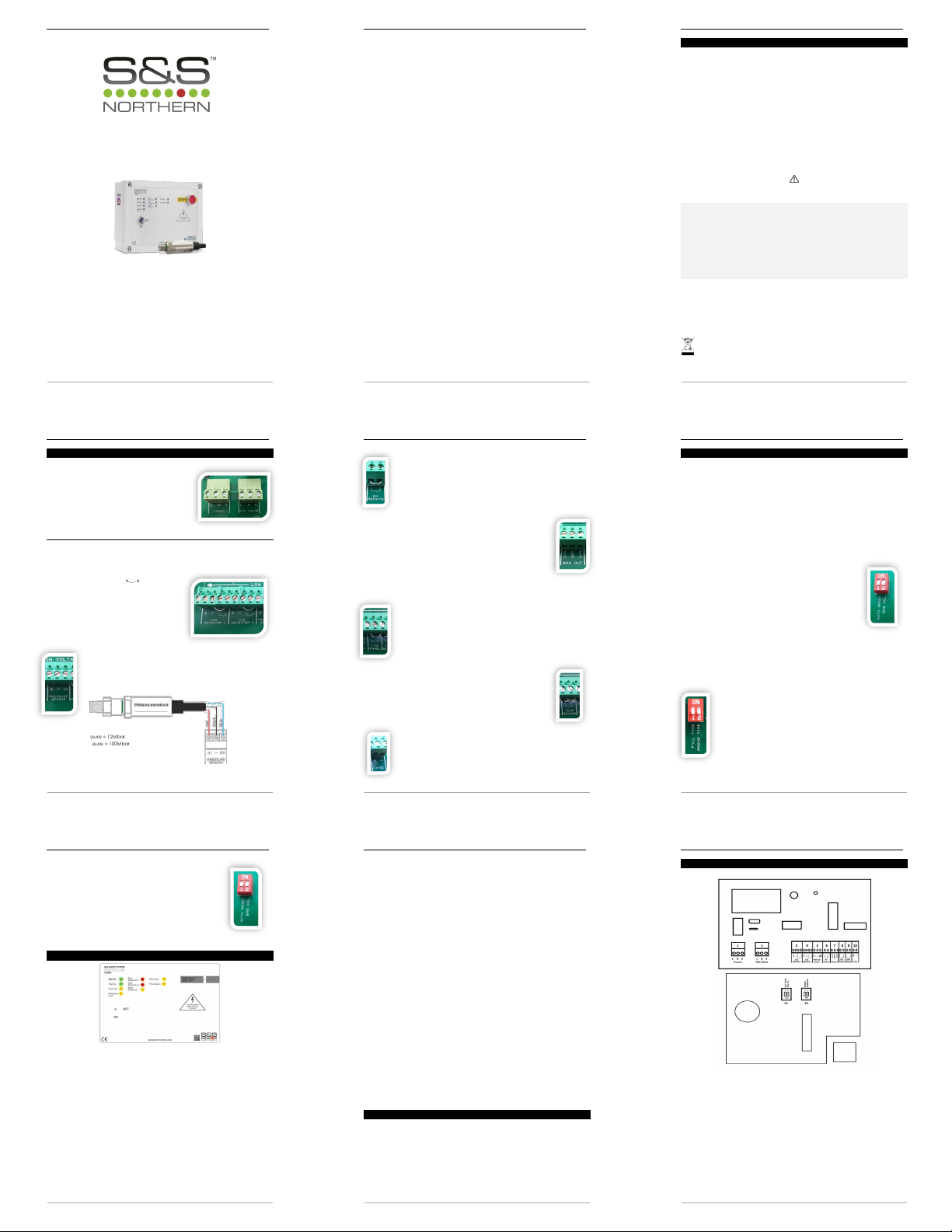
Merlin 1000BH
Gas proving and detection system
User Guide
Please read this guide carefully and retain for future use.
Merlin 1000BH User Guide
Rev: 08 08-19 2
Table of contents
1General Information..........................................................................................3
2Circuit Board Terminals .....................................................................................4
2.1 POWER ...........................................................................................................................4
2.2 GAS VALVE .................................................................................................................... 4
2.3 GAS DETECTOR 1 & 2 ....................................................................................................4
2.4 PRESSURE SENSOR ......................................................................................................... 4
2.5 EM REMOTE....................................................................................................................5
2.6 BMS OUT .........................................................................................................................5
2.7 FIRE PANEL .....................................................................................................................5
2.8 TEMP SENSOR................................................................................................................. 5
2.9 12VDC ............................................................................................................................5
3Operation & Setup Guidance...........................................................................6
3.1 How to turn the system on and off .............................................................................6
3.2 Using the Emergency Shut Off ....................................................................................6
3.3 Building Management System Connection ..............................................................6
3.4 Gas Fill and Prove Time ................................................................................................6
3.5 Auto Reset .....................................................................................................................7
4Panel LED Status................................................................................................. 7
5Maintenance .....................................................................................................8
61000BH Wiring Spec...........................................................................................9
7Manufacturer’s Warranty ................................................................................12
Merlin 1000BH User Guide
Rev: 08 08-19 3
1General Information
The Merlin 1000BH is a gas pressure proving & gas detection panel for use in various
applications.
The system comprises a control panel and a gas pressure sensor. The Merlin 1000BH can
receive connections from remote emergency shut-off buttons, two gas detectors, fire panel
and heat detector. It also can be integrated with a BMS.
The information contained within this guide should be referenced for typical installation and
operation only. For site specific requirements that may deviate from the information in this
guide –contact your supplier.
1.1 Panel Mounting
The control panel is designed for surface mounting using 4 mounting screws. Removing the
cover on the panel gives access to the circuit board, this should be removed before drilling
entry holes into the case.
Important Warning Statements
It is recommended that this device be commissioned upon installation and serviced annually.
Do not apply lighter gas or other aerosols to gas detectors –this will cause extreme damage.
Never ignore your device when in alarm.
This device requires a continual supply of electrical power –it will not work without power.
This device should not be used to substitute proper installation, use and/or maintenance of fuel burning
appliances including appropriate ventilation and exhaust systems.
Your product should reach you in perfect condition, if you suspect it is damaged, contact your supplier.
Information on waste disposal for consumers of electrical & electronic equipment. (EEE)
When this product has reached the end of its life it must be treated as Waste Electrical & Electronics Equipment
(WEEE). Any WEEE marked products must not be mixed with general household waste, but kept separate for
the treatment, recovery and recycling of the materials used.
Please contact your supplier or local authority for details of recycling schemes in your area.
Merlin 1000BH User Guide
Rev: 08 08-19 4
2Circuit Board Terminals
2.1 POWER
A 100-240VAC electrical supply should be externally fused
at 3 Amps and be connected to the terminals marked
[LNE POWER]
2.2 GAS VALVE
A gas solenoid valve should be powered using the
terminals marked [LNE GAS VALVE].
2.3 GAS DETECTOR 1 & 2
The terminals detailed on the circuit board as [GAS DETECTOR 1] and [GAS DETECTOR 2].
These connections are [+ -] and [ ] these can be
wired to a Merlin gas detector. Natural gas, Carbon
monoxide or LPG.
Please refer to the detector manual for more
information. If no detector is being used leave the link
in. Other detector types are available.
2.4 PRESSURE SENSOR
The terminals marked [+ - IN].
These wire to the gas pressure sensor which is screwed into the downstream
port on the gas solenoid valve.
Min Operating Pressure = 12Mbar
Max Operating Pressure = 100Mbar
ENSURE THIS IS WIRED AS PICTURED & SCREWED TO THE DOWNSTREAM PORT OF THE GAS SOLENOID VALVE
Merlin 1000BH User Guide
Rev: 08 08-19 5
2.5 EM REMOTE
The terminal for remote emergency shut-off buttons is marked as [EM REMOTE].
These connections are linked out as a factory setting.
Remote emergency shut-off buttons should be volt free.
2.6 BMS OUT
Terminals are available on the circuit board for connections to Building
Management systems.
This is a relay that changes state in alarm or when gas is on/off and can be
used in conjunction with the [12VDC] output and other external relays that
affect other devices and controls such as purge fans, audible alarms etc.
Marked on the circuit board as [BMS OUT] Normally Closed (N/C),
Common (COM) Normally Open (N/O).
These are volt free connections.
2.7 FIRE PANEL
The terminal for fire alarms is detailed on the circuit board as [FIRE PANEL].
These connections are linked out as a factory setting.
Fire alarms should be volt free and wired to the Merlin 1000BH using two-core
cable.
2.8 TEMP SENSOR
The terminal for heat detectors is detailed on the circuit board as [TEMP
SENSOR].
These connections are linked out as a factory setting.
Heat detectors should be volt free and wired to the Merlin 1000BH using
two-core cable.
2.9 12VDC
This is a permanent 12v DC output when there is power at the panel.
This is normally used to power a PM2 current monitor. (Supplied separately)
Merlin 1000BH User Guide
Rev: 08 08-19 6
3Operation & Setup Guidance
3.1 How to turn the system on and off
Turn the key switch to ON position.
Turn the key switch to OFF position or remove power.
3.2 Using the Emergency Shut Off
The Emergency shut off button is located on the front of the panel.
There is also a facility for remote shut off buttons to be wired in series.
The Emergency shut off button(s) will cut off the gas supply when activated.
To reinstate the system, the Emergency shut off button(s) will need to be reset and the panel
restarted.
3.3 Building Management System Connection
The Merlin 1000BH can be integrated with a BMS to make or break a
circuit on gas on/gas off, (valve open or valve closed). This will tell the
BMS whether or not electrical power is being sent to the solenoid.
There is a dip-switch located on the inside facia of the Merlin 1000BH
labelled [BMS SEL].
This is factory set in the ‘OFF’ position which signals the BMS on gas
on/gas off. When switched to the ‘ON’ position, the 1000BH will only
signal the BMS on a fault, i.e. gas detected, EM Stop pressed, etc.
3.4 Gas Fill and Prove Time
Gas fill and prove times are adjustable. There are two dip-switches located on the inside facia
of the Merlin 2000S labelled “Fill Time” and “Prove Time”. They are factory set in the ‘off’
position.
Fill and prove time can be changed by turning the relevant dip switch to on position.
FILL TIME is the amount of time the gas valve is open to fill the gas line.
Off –5 seconds
On –10 seconds
PROVE TIME is the amount of time the system tests the gas line for any leaks.
Off –30 seconds
On –50 seconds
Once the settings has been changed please remove power for 10 seconds.
Merlin 1000BH User Guide
Rev: 08 08-19 7
3.5 Auto Reset
The Merlin 1000BH has a built-in auto reset feature.
There is a dip-switch located on the inside facia of the Merlin 1000BH
labelled [Auto Reset]. This is factory set in the ‘OFF’ position.
When the power is restored after the power cut, the panel has to be
restarted manually.
On installation, this can be switched to the ‘ON’ position if required.
This will instruct the system to restart automatically when power is
restored after the power cut.
4Panel LED Status
When the system is connected to the mains supply, the red dot of the S&S logo located in the
bottom right corner of the panel will illuminate.
Gas on
When the key switch is turned on, the Merlin 1000BH will check the installation for gas leaks.
If gas proving is successful, the gas valve will open and the green ‘Gas On’ LED will illuminate.
ON = Gas On
OFF = Gas Off
Testing
This LED will illuminate GREEN for approximately 30 seconds when the panel is checking the
integrity of the gas installation upon start up.
GREEN = proving the gas line, do NOT operate any appliances
Test Fail
Under normal working conditions this LED is off. When the panel detects a gas leak on start-up,
the LED will illuminate AMBER. Gas valve will remain closed.
OFF = OK
ON = gas proving failed
Merlin 1000BH User Guide
Rev: 08 08-19 8
Pressure Low
Under normal working conditions the LED is off. The LED will illuminate AMBER when pressure of
the gas supply drops below 12mBar for 10 secs. The gas valve will close.
OFF = OK
ON = gas supply pressure low.
Gas Detector 1/ Gas Detector 2
Under normal working conditions this LED is off. If the external Merlin detector connected
detects gas this will show RED and the Gas valve will turn off.
OFF = OK
ON = Gas detected.
Heat Detector
Under normal working conditions this LED is off. If the temperature of the boilers reaches 72
Degrees Celsius or higher (Heat detector required), the LED will show AMBER and the Gas valve
will turn off.
OFF = OK
ON = High temperature detected (72 Degrees Celsius or higher)
EM Stop
If an emergency shut off button (either remote or on the panel) is pressed, the LED will
illuminate AMBER and the gas will be turned off. The EM Stop button must be re-set before
restarting the system.
OFF = OK
ON = EM Stop button pressed.
Fire Alarm Panel
If a fire alarm panel has been triggered, the LED will illuminate Amber and the gas will be
turned off. The Fire alarm panel must be re-set before restarting the system.
Off = OK
ON = Fire alarm panel triggered.
5Maintenance
To keep your panel in good working order, you must follow these steps:
DO carefully remove any accumulated dust from the outer enclosure once a month.
NEVER use detergents or solvents to clean your device –this may permenantly or temporarily
damage the panel
NEVER spray air fresheners, hair spray, paint or other aerosols near the device.
NEVER paint the device. Paint will seal vents and interfere with the device.
Merlin 1000BH User Guide
Rev: 08 08-19 9
61000BH Wiring Spec
1. POWER: Mains supply 100-240VAC.
2. GAS VALVE: Gas Solenoid Valve Power Output, 230VAC, Max 3A.
3. GAS DETECTOR 1: 12V power supply. VOLT FREE INPUT (detectors sold separately).
4. GAS DETECTOR 2: 12V power supply. VOLT FREE INPUT (detectors sold separately
5. PRESSURE SENSOR: Red + positive / Black –negative / Blue IN.
6. EM REMOTE: Remote emergency stop buttons and Fire Alarm input wired in series
(purchased separately). VOLT FREE INPUT
7. BMS OUT: Normally Closed, Common and Normally Open.
8. FIRE PANEL: (Supplied by others). VOLT FREE INPUT
9. TEMP SENSOR: (purchased separately). VOLT FREE INPUT
10. 12VDC: Permanent 12VDC output when there is power at the panel.
11. GAS & PROVE TIME SWITCH
12. AUTO RESET & BMS SELECTION SWITCH

Merlin 1000BH User Guide
Rev: 08 08-19 10
Merlin 1000BH User Guide
Rev: 08 08-19 11
Merlin 1000BH User Guide
Rev: 08 08-19 12
7Manufacturer’s Warranty
3 Year Limited Warranty
Warranty coverage: The manufacturer warrants to the original consumer purchaser, that this product will be free of
defects in material and workmanship for a period of three (3) years from date of purchase. The manufacturer’s liability
hereunder is limited to replacement of the product with repaired product at the discretion of the manufacture. This
warranty is void if the product has been damaged by accident, unreasonable use, neglect, tampering or other causes
not arising from defects in material or workmanship. This warranty extends to the original consumer purchaser of the
product only.
Warranty disclaimers: Any implied warranties arising out of this sale, including but not limited to the implied warranties of
description, merchantability and intended operational purpose, are limited in duration to the above warranty period. In
no event shall the manufacturer be liable for loss of use of this product or for any indirect, special, incidental or
consequential damages, or costs, or expenses incurred by the consumer or any other user of this product, whether due
to a breach of contract, negligence, strict liability in tort or otherwise. The manufacturer shall have no liability for any
personal injury, property damage or any special, incidental, contingent or consequential damage of any kind resulting
from gas leakage, fire or explosion. This warranty does not affect your statutory rights.
Warranty Performance: During the above warranty period, your product will be replaced with a comparable product if
the defective product is returned together with proof of purchase date. The replacement product will be in warranty for
the remainder of the original warranty period or for six months –whichever is the greatest.
CONTACT US:
S&S Northern Head Office
Tel: +44(0) 1257 470 983
Fax: +44(0) 1257 471 937
www.snsnorthern.com
South East Division
Tel: +44(0) 1702 291 725
Fax: +44(0) 1702 299 148
S&S Northern is the owner of this document and reserves all rights of modification without prior notice.
Other manuals for Merlin 1000BH
3
Other S&S Northern Measuring Instrument manuals


Popular Measuring Instrument manuals by other brands

ELTRA
ELTRA CS-580A operating manual

Sentry
Sentry Saf-T-Vise STV-HP2 Installation, operation & maintenance manual

CHY
CHY 506A Operator's manual

Badger Meter
Badger Meter DN15 user manual

DH Instruments
DH Instruments OIL INTENSIFIER SYSTEM instruction sheet

Endress+Hauser
Endress+Hauser Proline Prosonic Flow P 500 manual


