WATER BALANCE - Water balance requirements:
Salt 4000ppm –6000ppm pH 7.2 –7.4
Total Alkalinity 90 ppm –150 ppm Cyanuric Acid 40 ppm –65 ppm
Chlorine 1.5 ppm –2.0 ppm
CLEANING
Reverse Polarity Chlorinators have self-cleaning cells which means the maintenance
required is minimal. In exceptional cases, when the calcium content is abnormally high,
the chlorination may not totally remove all of the deposit. In this case the calcium level must
be adjusted to normal levels and the cell must be cleaned.
Procedure: Turn off the chlorinator, disconnect cell cable, and remove cell. The dirty cell
should be placed in a container with hydrochloric acid (HCI) solution: 8 parts water to one
part of HCI (30-33%). Calcium deposits will react with the HCI —producing gas. When gas
production has stopped, it means that the cell is completely cleaned and all the calcium has
dissolved. Rinse in fresh water as soon as possible —Leaving the cell in HCI solution for a
longer period will damage the cell! When cleaning is complete, dry the connections and
reinstall.
The chlorine production is regulated with the output control and daily running time. Your
chlorinator manufactures chlorine at a constant rate (i.e. the SM20 produces 20 grams of
chlorine per hour), and this is ideal for routine daily chlorination.
If during peak use the pool water looses its sparkle and looks “tired”, it probably needs to be
“shocked” or super chlorinated.
In situation such as this we recommend the use of liquid chlorine or sodium dichlorois
cyanurate, (sodium dichlor) to supplement and maintain chlorine levels.
The use of powdered calcium hypochlorite chlorine is not recommended.
If the residual chlorine in the pool is low, check:
a) chlorinator is not working long enough
b) the level of the chlorine stabiliser is too low
c) the cell needs to be cleaned
d) the pH of the water is too high
WARNING: Do not open unit - LIVE Components inside - danger of electric shock.
If supply cord is damaged, it shall be replaced by the manufacturer or its service agent or
similarly qualified person in order to avoid a hazard.
Chlorinators (models SM15, 25, 35 and 45 will have twenty four (24) months warranty for the
Power pack and 5 years pro-rata for the cell, in an 8 hr per day domestic installation.
In a commercial installation both power pack and cell are twelve (12) months . Power packs
are exchanged and electrodes need to be returned to the manufacturer.
This warranty applies to the original purchaser and is not transferable. All chlorinators are
fully factory tested, prior to being packed. If within twenty four (24) months of purchase,
mechanical or electrical faults do occur due to bad workmanship or faulty components,
then such parts will be repaired or replaced. No replacement part will be provided without
the return of the defective components. The manufacturer will not be liable of any
consequential loss or damage caused by operation outside the prescribed limits as outlined
in our instruction manual, incorrect installation, connection to incorrect power supply,
changing internal wiring for tariff connections, misuse, abuse, negligence, accidental
damage, normal wear and tear, or damage caused by water entry. In case of failure the
complete unit should be returned to the manufacturer or distributor. Forward and return
freight costs are the responsibility of the owner.
Thank you for choosing a SM Series salt water chlorinating system for your swimming pool.
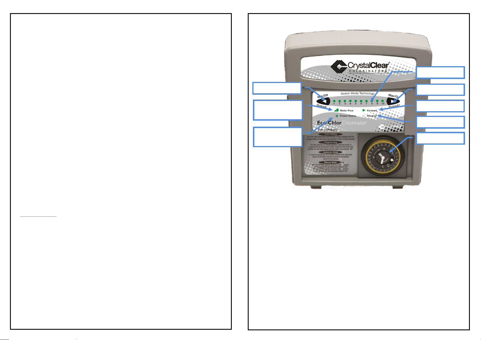
Eco-Chlor SM CHLORINATOR by Crystal Clear Chlorinators
EXPLANATION OF FUNCTIONS: POWER SUPPLY
BUTTON 1 - Single press of this button decreases chlorine production by approx. 5%.
In order to turn OFF the chlorinator it is necessary to press the button several
times to make sure all Chlorine Production Indicators are OFF.
BUTTON 2 - Single press of the button increases chlorine production by approx. 5%.
When all lights are ON the chlorine production is 100%.
BUTTON 3 - Chlorine Production Indicators. There are 10 indicators. Each indicator
corresponds to 10% of Chlorine production.
BUTTON 4 - If the water flow indicator is flashing or ON, the chlorinator is in the
Stand By mode and there is no water flowing through the cell. Please ensure
that the pump is running and there is water passing through the cell.
Takes a few minutes to reset.
BUTTON 5 - When this LED is ON then the unit is running in the forward direction.
This cleans calcium build up off the plates that had build up while in reverse.
BUTTON 6 - When this LED is ON then the unit is running in the reverse direction.
This cleans calcium build up off the plates that had build up while in forward.
BUTTON 7 - When the Power Status light is ON the chlorinator output is above the
LOW level and operating normally. When the LED is FLASHING then the
production is low and must be turned up (or salt is low or cell is failing).