Crystal Vision FRX HD User manual

Crystal Vision Ltd., Lion Technology Park, Station Road East, Whittlesford, Cambridge, CB22 4WL, England.
E-mail: [email protected] Website: www.crystalvision.tv Tel: +44(0) 1223 497049 Fax: +44(0) 1223 497059
FRX HD
Dual channel fibre optic
to HD or SD receiver

FRX HD User Manual R1.0 Crystal Vision
106/09/2007
Contents
1Introduction 3
FRX HD 4
2Hardware installation 5
2.1 Handling 5
2.2 Universal rear connectors 6
Rear module connections with RM28 7
2.3 General purpose interface 7
3Card edge operation 10
3.1 Card edge controls 10
4Using the front control panel 11
4.1 Module selected 11
The FRX HD menu structure 13
Channel A status 14
Channel B status 14
Miscellaneous information 15
5Statesman 16
5.1 Statesman operation 16
Status 17
Received power 17
6Trouble shooting 18
Basic fault finding guide 18

FRX HD User Manual R1.0 Crystal Vision
206/09/2007
Specification 19

Crystal Vision Introduction
FRX HD User Manual R1.0 306/09/2007
1Introduction
The FRX HD is a two-channel optical serial digital video receiver and distribution
amplifier for both High Definition and Standard Definition formats with up to two outputs
per channel.
The universal connection system allows a mixture of Crystal Vision modules in the frame.
The modules plug in the front and the rear connectors plug in the rear. Depending on
frame design, a hinged or removable front panel reveals LED indication of input and PSU
status when opened.
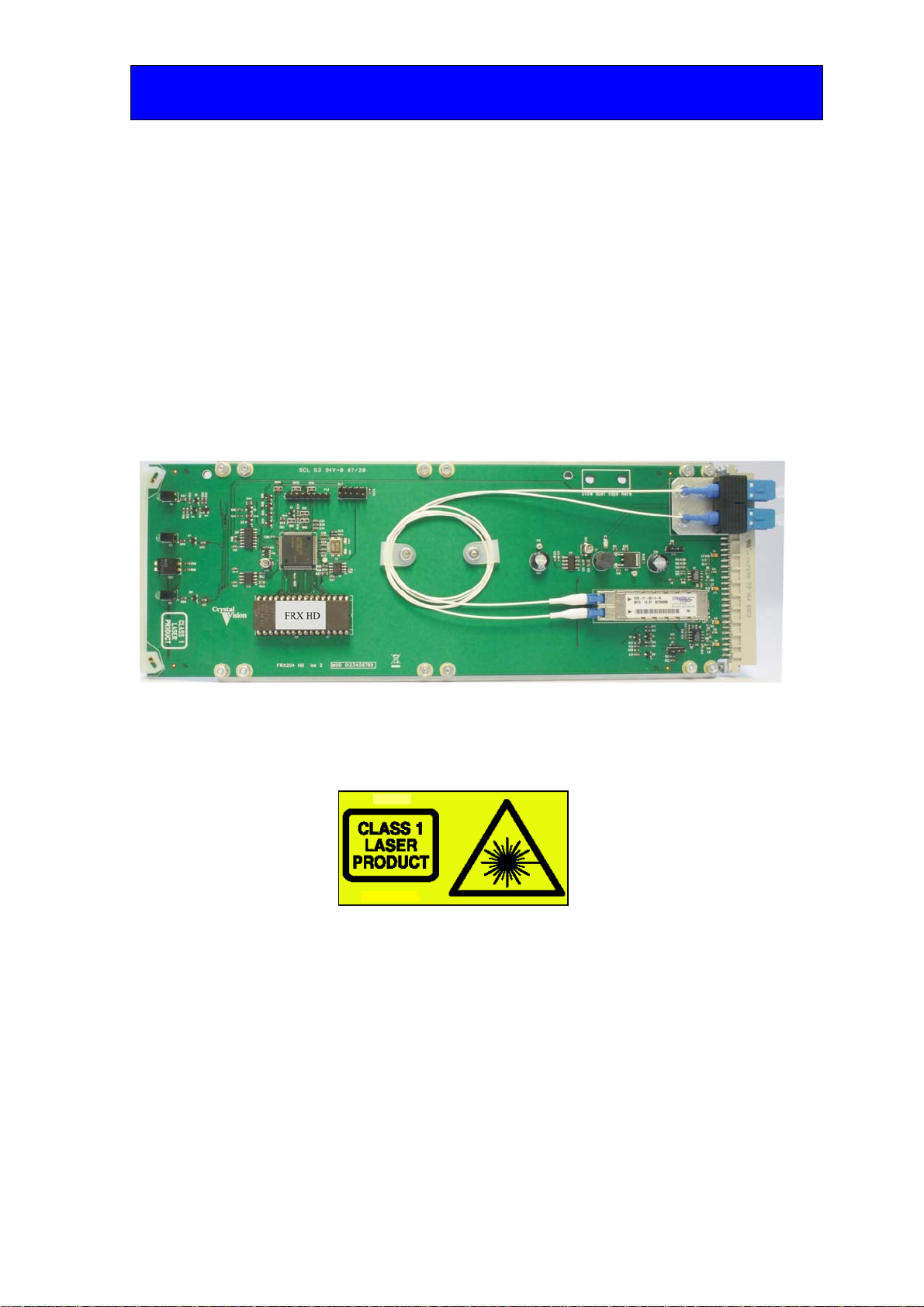
FRX HD two channel optical SDI distribution amplifier
The RM28 single slot rear connector provides two serial digital outputs per channel with
up to 24 modules in 4U of rack space.
The range of Crystal Vision optical boards has been designed to work in conjunction with
the Indigo 4 and the Indigo 2 and Indigo 1 frames of Issue 2 and above. The board may be
plugged into any of the PCB slots, the only proviso being where it needs to be placed
below a Standard Definition board. The rules governing frame configuration are
explained in the installation chapter.
The RM28 single slot rear connector provides two serial digital inputs and two optical
outputs with up to 24 modules in 4U of rack space.
Note: You can find the issue number of a frame inside at the front.
The Indigo frames have been designed to accept any selection of boards from our range of
Standard Definition, High Definition, audio and optical products. The high packing
density allows up to six modules in 1U, up to 12 modules in 2U and up to 24 modules in
4U.
Crystal Vision Introduction
FRX HD User Manual R1.0 406/09/2007
The main features of the FRX HD are as follows:
•Dual 1-in 2-out optical to HD/SD distribution amplifier
•LED optical input presence indication
•Selectable HD/SD slew rate
FRX HD
At the heart of the FRX HD is a two-channel state-of-the-art optical receiver module,
each channel consisting of an optical pin diode and signal conditioning circuitry coupled
to a two-output cable driver. The two identical channels of the FRX HD optical receiver
are completely independent of each other. Both channels are under the control of a CPU,
which monitors and reports their status.
FRX HD two-channel HD/SD optical receiver
Note: Caution must be taken when removing the FRX HD card if an optical
signal is present due to the possible damaging nature of high intensity light.
Although Crystal Vision optical products contain class 1 devices which are designed to be
safe under all circumstances, to avoid possible personal injury you are advised not to look
directly into a vacant optical slot where a third party piece of laser transmitting equipment
has been remotely connected to the Crystal Vision equipment.
Crystal Vision Hardware installation
FRX HD User Manual R1.0 506/09/2007
2Hardware installation
The Crystal Vision optical boards have been designed to work in conjunction with the
Indigo 4 frames, or Indigo 1 and 2 frames of issue 2 or higher. All modules can be
plugged in and removed while the frame is powered without damage.
Note: You can find the issue number of a frame inside at the front.
2.1 Handling
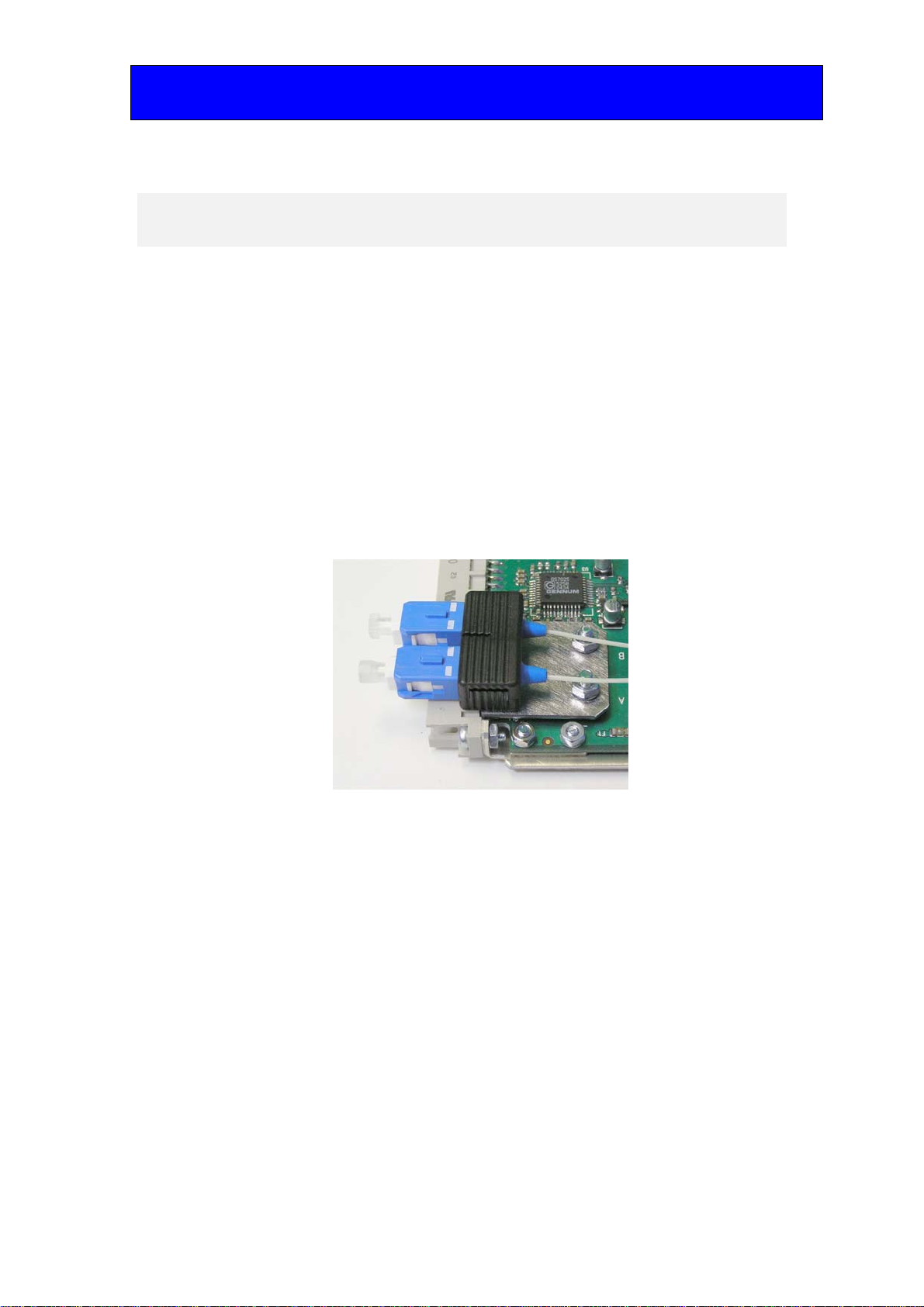
Due to its fragile nature, fibre optic equipment must be handled with care. Sharp blows or
snagging the fibre pigtails will fracture the internal glass filament and destroy its light
carrying ability. A degraded performance will also result if a build-up of dust and dirt film
on the connector ferrules is allowed to occur. It is strongly recommended that the supplied
dust caps are in place whenever the receiver card or rear module are de-mounted for any
reason.
PCB connectors with the dust caps fitted
The RM28 rear module is also fitted with dust caps on both sides of the optical connector.
The pair of dust caps that are internal to the frame must be removed before the rear
module is fitted. The external pair can then be removed when the fibre tails are connected.
It is also recommended that dust caps should be re-fitted if the fibre tails are to be
removed for any length of time. Should the FRX HD be removed for a while it is
recommended that the rear module should also be removed and stored with the dust caps
in place.

Crystal Vision Hardware installation
FRX HD User Manual R1.0 606/09/2007
RM28 rear module with dust caps fitted to both sides of the optical connector
2.2 Universal rear connectors
When using the RM28 single height rear connector, the 4U Indigo 4 frame will house up
to 24 modules and three power supplies. The 2U Indigo 2 frame will house up to 12
modules and dual power supplies, while the 1U Indigo 1 frame will house six modules
and a single or dual power supply. The Indigo DT desk top boxes do not currently accept
the Crystal Vision optical modules.
The Indigo frames have hinged front panels giving access to the PSU and all modules.
The universal frame wiring system allows any interface range modules to be fitted in any
position (1) with the use of pluggable rear modules.
(1) Due to height restraints, some restrictions apply when mixing optical modules with other Crystal Vision
modules.
Loading restrictions
The FRX HD can be loaded into any compatible frame’s slot but due to the extra height
of the FRX HD it is not possible to place cards from the Crystal Vision Standard
Definition or audio range directly above in certain positions. High Definition boards do
not share this restriction.
Frame t
yp
e xxxxxxxx xxxxxxxx xxxxxxxx
Optical module Optical module Optical module
xxxxxxxx xxxxxxxx xxxxxxxx
Indigo 4
Optical module Optical module Optical module
xxxxxxxx xxxxxxxx xxxxxxxx
Indigo 2 O
p
tical module O
p
tical module O
p
tical module
xxxxxxxx xxxxxxxx xxxxxxxx
Indigo 1 O
p
tical module O
p
tical module O
p
tical module
Optical cards loaded in these slots will not allow Standard Definition or audio cards to be
placed in the slot above.

Crystal Vision Hardware installation
FRX HD User Manual R1.0 706/09/2007
Rear module connections with RM28
RM28 fits in all frames Description
RM28
•24 modules in 4U, 12
modules in 2U & six in 1U
•All frame slots can be used
BNC I/O assignment
Optical Input (B) Optical serial digital video input (B)
Optical Input (A) Optical serial digital video input (A)
SDI OUT(A) Channel A HD/SD output
SDI OUT(A) Channel A HD/SD output
SDI OUT(B) Channel B HD/SD output
SDI OUT(B) Channel B HD/SD output
2.3 General purpose interface
The external GPI control lines 'a' to 'f' at the frame remote connectors is provided to allow
remote control and/or remote status indication. The FRX HD has four GPI output lines
assigned for status reporting.
GPI Connections
High (+5V) Low (less than 0.7V)
‘a’ no user connection
‘b’ no user connection
‘c’ no user connection
‘d’ no user connection
‘e’ Input A present Input A not present
‘f’ Input B present Input B not present
GPI lines are fitted with 6k8 Ohm pull-up resistors connected to the frame’s +5V. There
is also an output series resistor of 270 Ohm.

Crystal Vision Hardware installation
FRX HD User Manual R1.0 806/09/2007
4U frame GPI Connections
GPI lines ‘a’ to ‘f’ of each card connect to two of eight rear remote connectors as follows:
Slot no. ‘a’ pin ‘b’ pin ‘c’ pin ‘d’ pin ‘e’ pin ‘f’ pin
1 8 (1) 9 (1) 18 (1) 26 (1) 19 (2) 20 (2)
2 7 (1) 16 (1) 17 (1) 25 (1) 10 (2) 11 (2)
3 8 (3) 9 (3) 18 (3) 26 (3) 19 (4) 20 (4)
4 7 (3) 16 (3) 17 (3) 25 (3) 10 (4) 11 (4)
5 5 (1) 6 (1) 15 (1) 24 (1) 1 (2) 2 (2)
6 4 (1) 14 (1) 13 (1) 23 (1) 3 (2) 4 (2)
7 5 (3) 6 (3) 15 (3) 24 (3) 1 (4) 2 (4)
8 4 (3) 14 (3) 13 (3) 23 (3) 3 (4) 4 (4)
9 3 (1) 12 (1) 22 (1) 21 (1) 12 (2) 13 (2)
10 10 (1) 11 (1) 19 (1) 20 (1) 21 (2) 22 (2)
11 3 (3) 12 (3) 22 (3) 21 (3) 12 (4) 13 (4)
12
Upper
10 (3) 11 (3) 19 (3) 20 (3) 21 (4) 22 (4)
‘a’ pin ‘b’ pin ‘c’ pin ‘d’ pin ‘e’ pin ‘f’ pin
1 8 (5) 9 (5) 18 (5) 26 (5) 19 (6) 20 (6)
2 7 (5) 16 (5) 17 (5) 25 (5) 10 (6) 11 (6)
3 8 (7) 9 (7) 18 (7) 26 (7) 19 (8) 20 (8)
4 7 (7) 16 (7) 17 (7) 25 (7) 10 (8) 11 (8)
5 5 (5) 6 (5) 15 (5) 24 (5) 1 (6) 2 (6)
6 4 (5) 14 (5) 13 (5) 23 (5) 3 (6) 4 (6)
7 5 (7) 6 (7) 15 (7) 24 (7) 1 (8) 2 (8)
8 4 (7) 14 (7) 13 (7) 23 (7) 3 (8) 4 (8)
9 3 (5) 12 (5) 22 (5) 21 (5) 12 (6) 13 (6)
10 10 (5) 11 (5) 19 (5) 20 (5) 21 (6) 22 (6)
11 3 (7) 12 (7) 22 (7) 21 (7) 12 (8) 13 (8)
12
Lower
10 (7) 11 (7) 19 (7) 20 (7) 21 (8) 22 (8)
Table shows pin number (Remote number)
Note: Remote 1, Remote 3, Remote 5 and Remote 7 are 26-way high density D-Type female
sockets. Frame ground is pin 2 and +5V @500mA is pin 1 in each case.
Remote 2, Remote 4, Remote 6 and Remote 8 are 26-way high density D-Type male
plugs. Frame ground is pin 6 and +5V @500mA is pin 15 in each case.
Crystal Vision Hardware installation
FRX HD User Manual R1.0 906/09/2007
2U frame GPI Connections
GPI lines ‘a’ to ‘f’ of each card connect to two of four rear remote connectors as follows:
Slot no. ‘a’ pin ‘b’ pin ‘c’ pin ‘d’ pin ‘e’ pin ‘f’ pin
1 8 (1) 9 (1) 18 (1) 26 (1) 19 (2) 20 (2)
2 7 (1) 16 (1) 17 (1) 25 (1) 10 (2) 11 (2)
3 8 (3) 9 (3) 18 (3) 26 (3) 19 (4) 20 (4)
4 7 (3) 16 (3) 17 (3) 25 (3) 10 (4) 11 (4)
5 5 (1) 6 (1) 15 (1) 24 (1) 1 (2) 2 (2)
6 4 (1) 14 (1) 13 (1) 23 (1) 3 (2) 4 (2)
7 5 (3) 6 (3) 15 (3) 24 (3) 1 (4) 2 (4)
8 4 (3) 14 (3) 13 (3) 23 (3) 3 (4) 4 (4)
9 3 (1) 12 (1) 22 (1) 21 (1) 12 (2) 13 (2)
10 10 (1) 11 (1) 19 (1) 20 (1) 21 (2) 22 (2)
11 3 (3) 12 (3) 22 (3) 21 (3) 12 (4) 13 (4)
12 10 (3) 11 (3) 19 (3) 20 (3) 21 (4) 22 (4)
Table shows pin number (Remote number)
Note: Remote 1 and Remote 3 are 26-way high density D-Type female sockets. Frame ground
is pin 2 and +5V @500mA is pin 1 in each case.
Remote 2 and Remote 4 are 26-way high density D-Type male plugs. Frame ground is
pin 6 and +5V @500mA is pin 15 in each case.
1U frame GPI connections
GPI lines ‘a’ to ‘f’ of each card connect to the two rear remote connectors as follows:
Slot no. ‘a’ pin ‘b’ pin ‘c’ pin ‘d’ pin ‘e’ pin ‘f’ pin
1 8 (1) 9 (1) 18 (1) 26 (1) 19 (2) 20 (2)
2 7 (1) 16 (1) 17 (1) 25 (1) 10 (2) 11 (2)
3 5 (1) 6 (1) 15 (1) 24 (1) 1 (2) 2 (2)
4 4 (1) 14 (1) 13 (1) 23 (1) 3 (2) 4 (2)
5 3 (1) 12 (1) 22 (1) 21 (1) 12 (2) 13 (2)
6 10 (1) 11 (1) 19 (1) 20 (1) 21 (2) 22 (2)
Table shows pin number (Remote number)
Note: Remote 1: 26-way high density D-Type socket. Frame ground is pin 2 and +5V @500mA is
pin 1.
Remote 2: 26-way high density D-Type plug. Frame ground is pin 6 and +5V @500mA
is pin 15.

Crystal Vision Card edge operation
FRX HD User Manual R1.0 10 06/09/2007
3Card edge operation
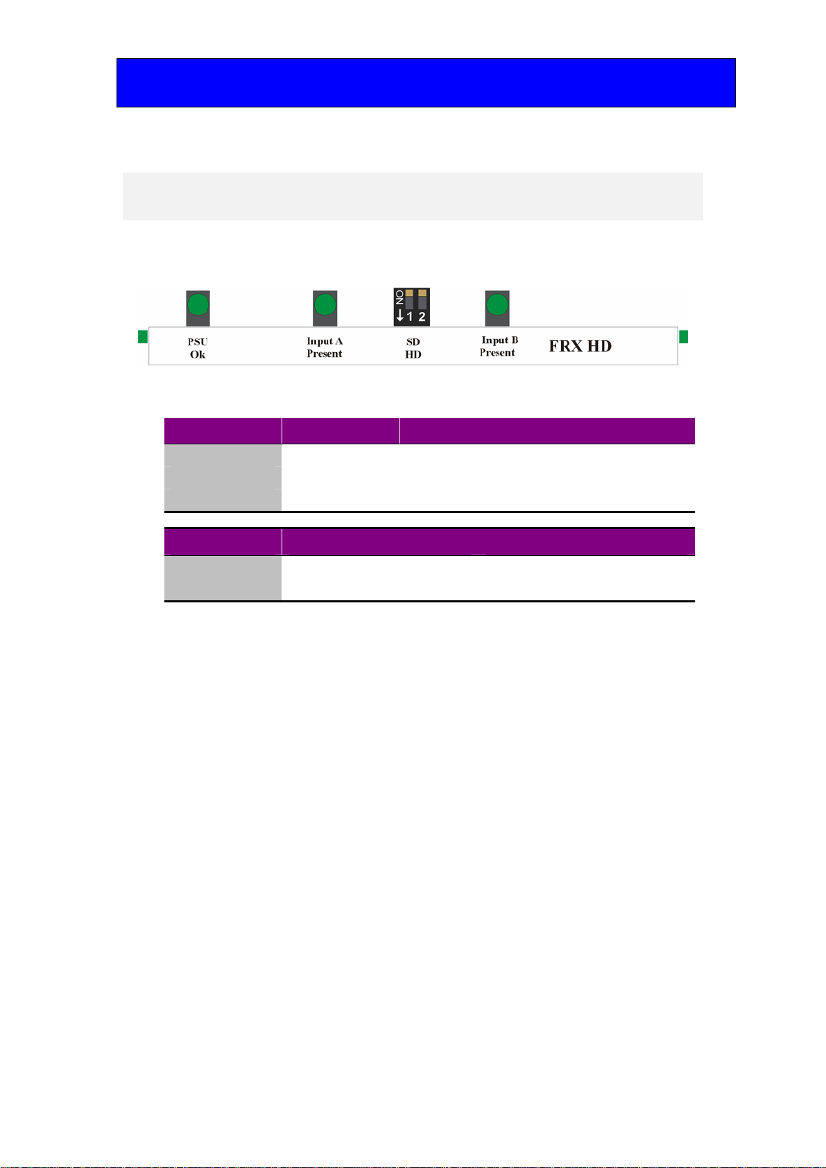
3.1 Card edge controls
The front edge of the FRX HD card provides power rail monitoring slew rate selection
and signal status.
FRX HD front edge view
LED Location/colour Meaning when lit
Input A Present Green There is an optical input present on input A.
Input B Present Green There is an optical input present on input B.
PSU Ok Green Power supply voltage present.
Switch SD/HD Up Down
Input A Rise/fall time to SMPTE 259M Rise/fall time to SMPTE 292M
Input B Rise/fall time to SMPTE 259M Rise/fall time to SMPTE 292M
Crystal Vision Using the front control panel
FRX HD User Manual R1.0 11 06/09/2007
4Using the front control panel
4.1 Module selected
This operational guide assumes that the panel has been set up according to the panel set
up procedure described in the Crystal Vision Control Panel manual.
Note: It is ESSENTIAL that the panel set up procedure is followed and any old or unknown
passwords cleared prior to using the panel for the first time.
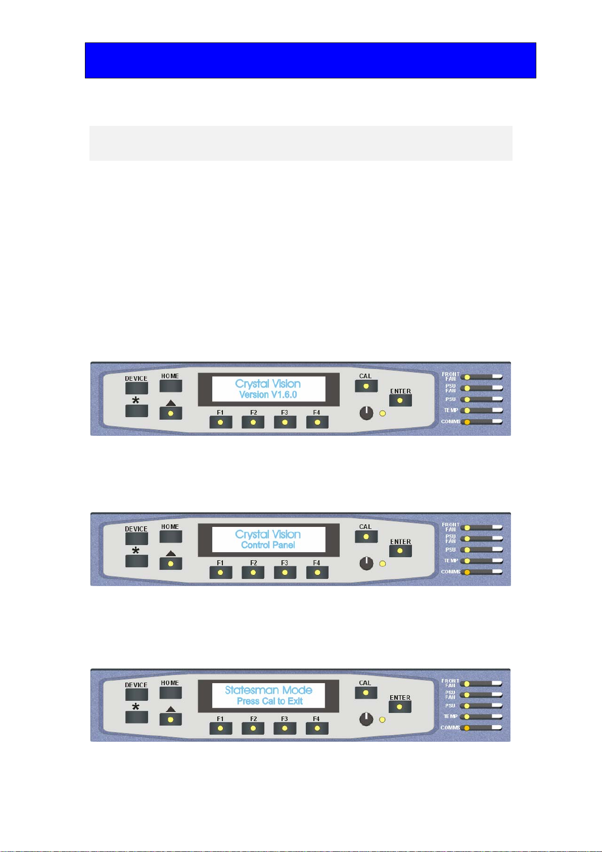
At power up, the two-line 20-character screen will display ‘Crystal Vision’ followed by
the firmware version number for the control panel. All eight control panel key LEDs will
illuminate.
The Crystal Vision control panel start up display
'Control Panel' then briefly replaces the version number display.
If the control panel firmware has been updated for Statesman control (version 1.5.0 or
higher), Statesman Mode will be entered and the message ‘Press CAL to Exit’ will be
displayed and the CAL LED will light.
Statesman mode is entered by default
Crystal Vision Using the front control panel
FRX HD User Manual R1.0 12 06/09/2007
To continue with control panel operation or configuration, press the CAL key once. A
second press of the CAL key will return to Statesman control.
The control panel will display the name of the card that first responds to the polling
request together with its location number.
The location number consists of the frame number plus the card position in the frame.
Navigating the display
The functions assigned to control panel keys are:
•DEVICE – enters Device menu to select a card or show cards available / enters
panel set up when held down during power up / shows frame status when
pressed from Statesman mode
•CAL – enters or leaves Statesman mode / enters panel diagnostics mode when
held down during power up / updates the display
•Asterisk – enters board rename menu from the Device menu
•F1 to F4 – soft keys, function assigned within each menu
•HOME – moves the display to the home menu
•ENTER – accepts current selection
•Upward arrow – used to move up the menu structure / enters lock panel menu
from the Device menu
•Rotary control – shaft encoder used to select options or variable data
Note: Please refer to the Crystal Vision Control Panel manual for details of the Panel Setup,
Lock Panel and Diagnostic menus.
Selecting an FRX HD
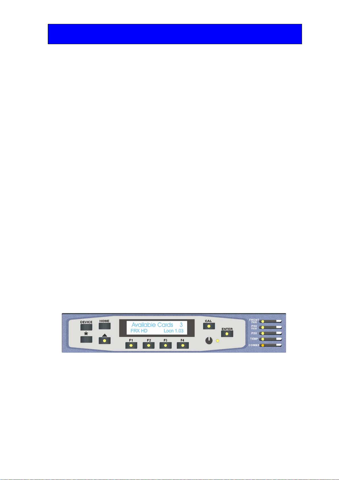
To select a particular card in a frame, press the DEVICE key to go to the Device menu.
The top line of the display will show ‘Available Cards X’, where X is the number of cards
that have responded so far to the polling request.
The available cards menu
Rotate the shaft encoder and the bottom row will display the successfully polled cards by
name and location or slot number.
In the example above, the card displayed is located in the first frame in slot number 3.
When the desired card is selected press the ENTER key to access that card’s HOME
menu.
The message shows that an FRX HD has been selected.
Crystal Vision Using the front control panel
FRX HD User Manual R1.0 13 06/09/2007
The FRX HD home menu
Display Updating
The values displayed on an active front panel are only updated as the FRX HD card is
polled. Therefore the display may take a few seconds to update after a change in status.
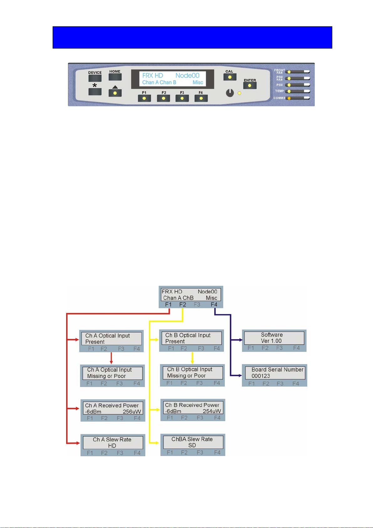
The FRX HD menu structure
The main top-level menu is obtained by pressing the HOME button. Menu keys are
illuminated when active and when further menus are available. There are three menu
selections available:
•Channel A – press F1
•Channel B – press F2
•Miscellaneous – press F4
When a sub menu has been selected, further options may be obtained by using the Shaft
control to scroll through them.
The following chart shows the available FRX HD menus. The actual menus available may
vary slightly as software is updated.
Note: Function key LEDs are illuminated when active.

Crystal Vision Using the front control panel
FRX HD User Manual R1.0 14 06/09/2007
Channel A status
Pressing button F1 from the home menu will show status information for channel A.
FRX HD channel A status menu Description
From the Home menu, press F1 to select the Channel A status
menu, which is then traversed by rotating the shaft control.
Rotate the shaft control to view the channel A input status.
No optical input or level too small.
Received power in microwatts and dBm.
Rotate the shaft control to view channel A output slew rate
selected.
HD, SD.
Channel B status
Pressing button F1 from the home menu will show status information for channel A.
FRX HD channel B status menu Description
From the Home menu, press F1 to select the Channel B status
menu, which is then traversed by rotating the shaft control.
Rotate the shaft control to view the channel B input status.
No optical input or level too small.
Received power in microwatts and dBm.
Rotate the shaft control to view channel B output slew rate
selected.
HD, SD.
Crystal Vision Using the front control panel
FRX HD User Manual R1.0 15 06/09/2007
Slew rate
Standard Definition Rise/fall time to SMPTE 259M
High Definition Rise/fall time to SMPTE 292M
Received power is given in both microwatts and dBm. dBm are particularly useful for
monitoring the optical budget.
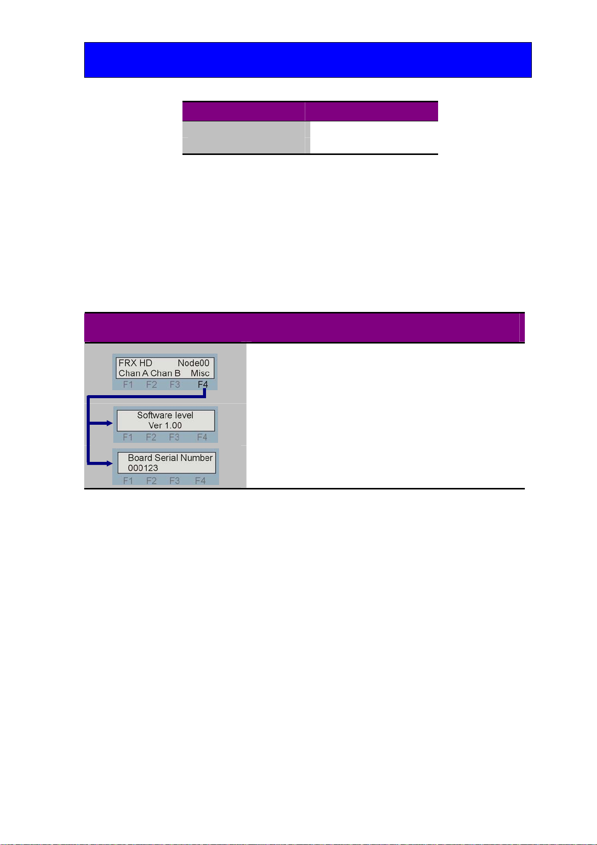
Miscellaneous information
Pressing button F4 from the home menu will show miscellaneous information about the
FRX HD module.
FRX HD Miscellaneous menu Description
From the Home menu, press F4 to select the miscellaneous menu,
which is then traversed by rotating the shaft control.
Rotate the shaft control to view the currently fitted software
version.
Rotate the shaft control to view the electronically stored board
serial number.

Crystal Vision Statesman
FRX HD User Manual R1.0 16 06/09/2007
5Statesman
The Crystal Vision Statesman PC control software is designed to control a range of
Crystal Vision modules via serial control from a PC. Statesman provides a user friendly
means of configuring and operating Crystal Vision modules with the benefit of “see-at-a-
glance” status monitoring.
The main Statesman application communicates with each module in a frame through a
Statesman capable or active control panel. An active panel or REMIND remote control
panel must be fitted to allow for Statesman control.
5.1 Statesman operation
The initial view will show an Explorer style view of the connected frames and modules.
Double clicking on a module will enable the display of the main application menus.
Statesman main application window
The two large control panes shown in the upper and lower halves of the window may
display different menus for the same card, or controls for different cards. Click on the
horizontal button-bar between the two panes to close the lower plane or drag the button to
vary the size of the panes.
Note: For further details of Statesman configuration and operation please refer to the Statesman
manual.

Crystal Vision Statesman
FRX HD User Manual R1.0 17 06/09/2007
Status
The status panel gives information about input presence and slew rate setting for both
channels. Board power rail condition is also shown. When no input is present the green
presence LEDs will show red.
Status monitoring
Received power
The received power for each channel is displayed pictorially on a pair of trend graphs
with a Y axis of approximately 5 minutes.
Received power display
The following formula can be used to convert microwatts to dBm:
dBm = 10 log (microwatts/1000)
Crystal Vision Trouble shooting
FRX HD User Manual R1.0 18 06/09/2007
6Trouble shooting
The front edge of the FRX HD card provides power rail monitoring, slew rate selection
and signal status.
FRX HD front edge view
LED Location/colour Meaning when lit
Input A Present Green There is a modulated optical input present on input A.
Input B Present Green There is a modulated optical input present on input B.
PSU Ok Green Power supply voltage present.
Switch SD/HD Up Down
Input A Rise/fall time to SMPTE 259M Rise/fall time to SMPTE 292M
Input B Rise/fall time to SMPTE 259M Rise/fall time to SMPTE 292M
Basic fault finding guide
The Power OK LEDs are not illuminated
Check that the frame PSU is functioning – refer to the appropriate frame manual for detailed
information.
Check that the card is seated correctly in the frame.
There is no video output
Check that valid video input is present and that any cabling is intact.
Optical inputs are present but no video output
Check that the optical signal contains valid serial digital video.
The video output is low quality
Check that the maximum cable length has not been exceeded for both the optical input and video
outputs.
Check that the optical connectors have not become contaminated.
Check that the correct slew rate is selected.
Check that the received power is sufficient.
Re-setting the card
If required, the card may be reset by simply removing the frame power and re-applying it after a few
seconds or by removing the card from the frame and then re-inserting it.
It is safe to re-insert the card whilst the frame is powered

Crystal Vision Specification
FRX HD User Manual R1.0 19 06/09/2007
Specification
General
Dimensions 100mm x 266mm module with DIN 41612 connector
Weight 200g
Power consumption 2.5 W
Inputs
Optical wavelength 1270-1610nm, 1300nm nominal
Connector type SC
Input level maximum -1dBm
Input level minimum -20dBm
Fibre Single mode
Outputs
Number Two channels with two outputs per channel
Video HD or SD SDI 270Mb/s to 1.485Gb/s serial digital compliant to
EBU 3267-E, SMPTE 259M and SMPTE 292M
Cable equalisation HD. Up to 140m with Belden 1694 or equivalent (Belden 8281 or
equivalent up to 100m)
SD (270Mb/s) >250 metres
Status monitoring
LED display Front of card edge visual monitoring with LED indicators to
indicate:
PSU rails within limits, optical input present
GPI output Input present Channel A and Channel B
Table of contents
Other Crystal Vision Receiver manuals


Popular Receiver manuals by other brands

ViewSat
ViewSat VS2000 ULTRA user manual

Nortek Security & Control
Nortek Security & Control 2GIG Vario Wireless Receiver installation instructions

Extron electronics
Extron electronics XTP T HDMI user guide

THOMSON
THOMSON CS1200VD - PART 1 manual

Onkyo
Onkyo TX-SR55 instruction manual

Lumistar
Lumistar LS-28-DRSM Quick start manual

Lectronics
Lectronics Venue 2 VRM2WBL installation guide

DTM System
DTM System GALACTIC NANO 868 installation manual

Belkin
Belkin 8820TT00587 user manual

Yamaha
Yamaha RX-S601 Firmware update manual

Sirius Satellite Radio
Sirius Satellite Radio Streamer Replay SIR-STRC1 user guide

StarTech.com
StarTech.com AUDIOEXTRX instruction manual


