HITESCA ECHBA 201 Instruction manual

IOM_ECHBA-ECHA_201a1201_208035_191200_EN
EVAPORATION UNITS AIR –AIR
SOLO FRIO
ECHBA-ECHA
ECCEECHAECHA
Cooling Only
Heat Pump
Models: 201 │ 251 │ 351 │371 │401 │501 │701 │721 │751 │801 │1001 │ 1201
Cooling Capacities: from 5.6 kW to 33.5 kW
Heating Capacities: from 6.1 kW to 37.2 kW
INSTALLATION, OPERATION & MAINTENANCE MANUAL

Thank you for trusting the Hitecsa Products. Our company has been offering the market an extended range of specialized units for
air conditioning and cooling installations for over 35 years. Our approach is based on efficiency, flexibility and on practical solutions.
This has been the hallmark of our product catalogue.
The versatility of our factory allows us to deliver solutions that can meet any requirement and we endeavour solving any problem
that may arise in designing and implementing air conditioning installations.
From all of us at Hiplus Aire Acondicionado, once again, thank you very much.

3
IOM_ECHBA-ECHA_201a1201_208035_191200_EN
ECHBA-ECHA
EVAPORATION UNITS AIR-AIR
INDEX
INTRODUCTION .......................................................................................................................... 4
REGULATIONS AND CERTIFICATIONS .......................................................................................... 5
SAFETY PRECAUTIONS ................................................................................................................ 6
TECHNICAL SPECIFICATIONS........................................................................................................ 7
TRANSPORT & RECEPTION .......................................................................................................... 8
INSPECTION AT RECEPTION ....................................................................................................8
RIGGING .................................................................................................................................8
STORAGE ................................................................................................................................8
INSTALLATION ............................................................................................................................ 9
INSTALLATION LOCATION.......................................................................................................9
UNIT SETTLEMENT..................................................................................................................9
SERVICE AREA (MM) ................................................................................................................9
WEIGHT
DISTRIBUTION
(
KG
)
.................................................................................................9
DIMENSIONS ........................................................................................................................10
Modelo ECHBA-ECHA 201 .................................................................................................10
Modelo ECHBA-ECHA 251 .................................................................................................10
Model ECHBA-ECHA 351 ...................................................................................................11
Models ECHBA-ECHA 371 –401 –501 ..............................................................................11
Models ECHBA-ECHA 701 –721 –751 –801 ....................................................................12
Model ECHBA-ECHA 1001 .................................................................................................12
Model ECHBA-ECHA 1201 .................................................................................................13
DRAINAGE ............................................................................................................................13
AIR DUCTS.............................................................................................................................14
DESIGN OF THE REFRIGERANT PIPES ....................................................................................14
ELECTRICAL INSTALLATION...................................................................................................14
ELECTRICAL DATA ......................................................................................................................14
Electrical connections ........................................................................................................15
OPERATION............................................................................................................................... 16
BEFORE START UP.................................................................................................................16
START UP ..............................................................................................................................16
INDOOR FAN TRANSMISSION ADJUSTMENT ........................................................................17
OPERATION LIMITS...............................................................................................................18
MAINTENANCE ......................................................................................................................... 19
CONSERVATION AND CLEANING ..........................................................................................19
ECHBA-ECHA

4
IOM_ECHBA-ECHA_201a1201_208035_191200_EN
ECHBA-ECHA
EVAPORATION UNITS AIR-AIR
INTRODUCTION
Purpose of this Manual
The present manual together with any other technical document such as refrigeration or hydraulic lines
drawings and electrical diagrams among others have been issued to provide the necessary information for
installation, start-up and maintenance of the unit. Therefore it is essential to read the instructions very
carefully. Please contact us if your machine is equipped with an option or any special modification that are
not mentioned in the present manual.
Make sure that all the necessary information for the correct installation of the system is included in the
manuals that have been supplied together with this unit and/or the rest of the indoor units, accessories, etc.
The manufacturer declines any responsibility in case of people/animals injuries or material damages
resulting from an incorrect use of the unit and/or non-compliance with these instructions.
In case of different interpretations and/or errors, the priority order of validity of the given documents will be:
1. Name plate of the unit stating the specifications. 2. IOM (the present document), 3. EDM, technical
catalogue, 4. UM user manuals.
Storage of the Manual
This manual and the electrical diagram of the unit must be preserved and remain available to the operator for any further
consultation.
Updating the Data
The continuous improvement in design and performance to which we are committed to gives us the right to modify the
specifications of our products without prior notice.
Electrical Supply
Check that the electrical network features comply with the data shown in the data nameplate of the unit.
Local Safety Regulations
Observe and analyse all the possible causes of accidents that may arise in the place or places of installation of the units,
check all the medium and the tools that will be used, etc. It is not possible to anticipate each one of the potential
circumstances of danger in this manual. Respect the valid local security standards during installation.
Principles of Security
The unit has been designed and built so that it does not represent any risk to the health and safety of people. Appropriate
solutions for the project have been planned to eliminate the possible causes of risk during installation.
Installation
Utilization
The unit will be used only for the purpose it has been designed for. Any other use does not imply any kind of liability or
responsibility from the manufacturer.
Please read carefully the present document. Any damage to the equipment caused by an incorrect
installation will not be covered by the insurance. Any installation operation shall be completed according
to the instructions of the manufacturer and carried out by certified personnel. This document has been
issued for installers, however, should you find the instructions not clear enough, please do not hesitate
to contact us.
Reminder: all operations shall be completed according to the local security regulations.

5
IOM_ECHBA-ECHA_201a1201_208035_191200_EN
ECHBA-ECHA
EVAPORATION UNITS AIR-AIR
INTRODUCTION
Incorrect Operation
In case of breakdowns or operation faults, turn the unit off.
Periodic Inspections and Maintenance
Carry out periodic inspections to detect possible damaged or broken parts. If these parts are not repaired,
people injuries or material damages could be caused. Disconnect the power supply of the unit before
carrying out any maintenance operation.
Make sure that the maintenance areas are accessible. If these areas have to be invaded by the lateral air
supply and/or return ducts, verify that the design of the ducts allows the access to the fans and that they
are not a hindrance when replacing the filters. If that is not possible make sure access is possible from the
other side.
All operations shall be carried out in accordance with the local safety regulations.
Repairing Operations
The reparations shall always and exclusively be completed by trained personnel previously authorized by
the manufacturer and only original spares shall be used. The safety devices of the unit may be damaged
in case of non-compliance with these warnings.
Modifications
The manufacturer will not respond to possible warranty claims and damages of the unit in case of electrical and/or
mechanical modifications. The unauthorized manipulation, reparation or modification of the unit will automatically invalidate
the warranty.
Packaging and Replacement of Equipment
The material of the package (plastic bags, insulating materials, nails, etc.) is a potential source of danger.
Consequently, it should be kept out of the reach of children and properly recycled according to the valid
local safety regulations.
Do not mix this product with household waste at the end of its life. Due to the refrigerant, oil and other
components contained in this product, it must be dismantled by professional installers. All the
waste, depending on its nature shall be sent to recycling, composting or treatment plants, or to an
authorized management agency in accordance with the current local legislations.
Refrigerant
This product is hermetically sealed and its operation depends on the use of R-410A which is a HFC fluorinated greenhouse
gas.
REGULATIONS AND CERTIFICATIONS
ISO 9001 CERTIFICATION: HIPLUS AIRE ACONDICIONADO S.L., by endeavouring to always gain the maximum
satisfaction from their customers, obtained the ISO 9001: Quality System for its production activity. That result shows our
continuous determination to improve quality and the reliability of all our products. Our commercial activities, design, raw
materials, production processes and after-sales service represent the means to reach our goal.
CE MARKING: Our products are CE marked according to the essential requirements of the applicable EC directives and
their last modifications and comply with the national legislation of each country.

6
IOM_ECHBA-ECHA_201a1201_208035_191200_EN
ECHBA-ECHA
EVAPORATION UNITS AIR-AIR
SAFETY PRECAUTIONS
DANGER
• In case of folding electrical panels, before folding them up in order to access to the interior of the machine, it is
MANDATORY to disconnect the power supply hose from the electrical voltage, IT MUST ALWAYS BE FREE OF
VOLTAGE for this operation.
• Do not touch or adjust the safety elements inside of any unit of the system. Use only original spare parts in
repairs and install them in the same position where old parts were placed.
• The installation and maintenance of the air conditioning equipment could be dangerous because the system is
under pressure, some of its elements have high temperatures and include electrical components.
• Do not install the unit in the explosive atmosphere.
ATTENTION!
• Only qualified and trained service staff (technical service) must make the installation, commissioning and carry out
maintenance works. Unqualified staff can only make basic tasks such as cleaning and replacement of filters, etc.
• Prevent access to children so they cannot play with the appliances.
• In every visit, all precautions must be taken into account: those recommended in the installation, operation and
maintenance instructions, as well as the ones indicated in labels of the unit. Do not forget to strictly follow any other safety
precautions. .
• DO NOT introduce objects into the air inlets or outlets that can be drawn into the fan, people, etc.
• Use safety glasses, work gloves and any other safety accessory necessary.
• For brazing operations use a quenching cloth and take precautions to have at close distance a fire extinguisher.
• This product contains fluorinated greenhouse gases, its leakage can cause displacement of air and cause insufficient
oxygen to breath.
• All safety recommendations must be followed.
Before starting installation, service or maintenance, turn off the main power switch in order
to avoid electrical shock that may cause personal damages.
WARNING!
7
IOM_ECHBA-ECHA_201a1201_208035_191200_EN
ECHBA-ECHA
EVAPORATION UNITS AIR-AIR
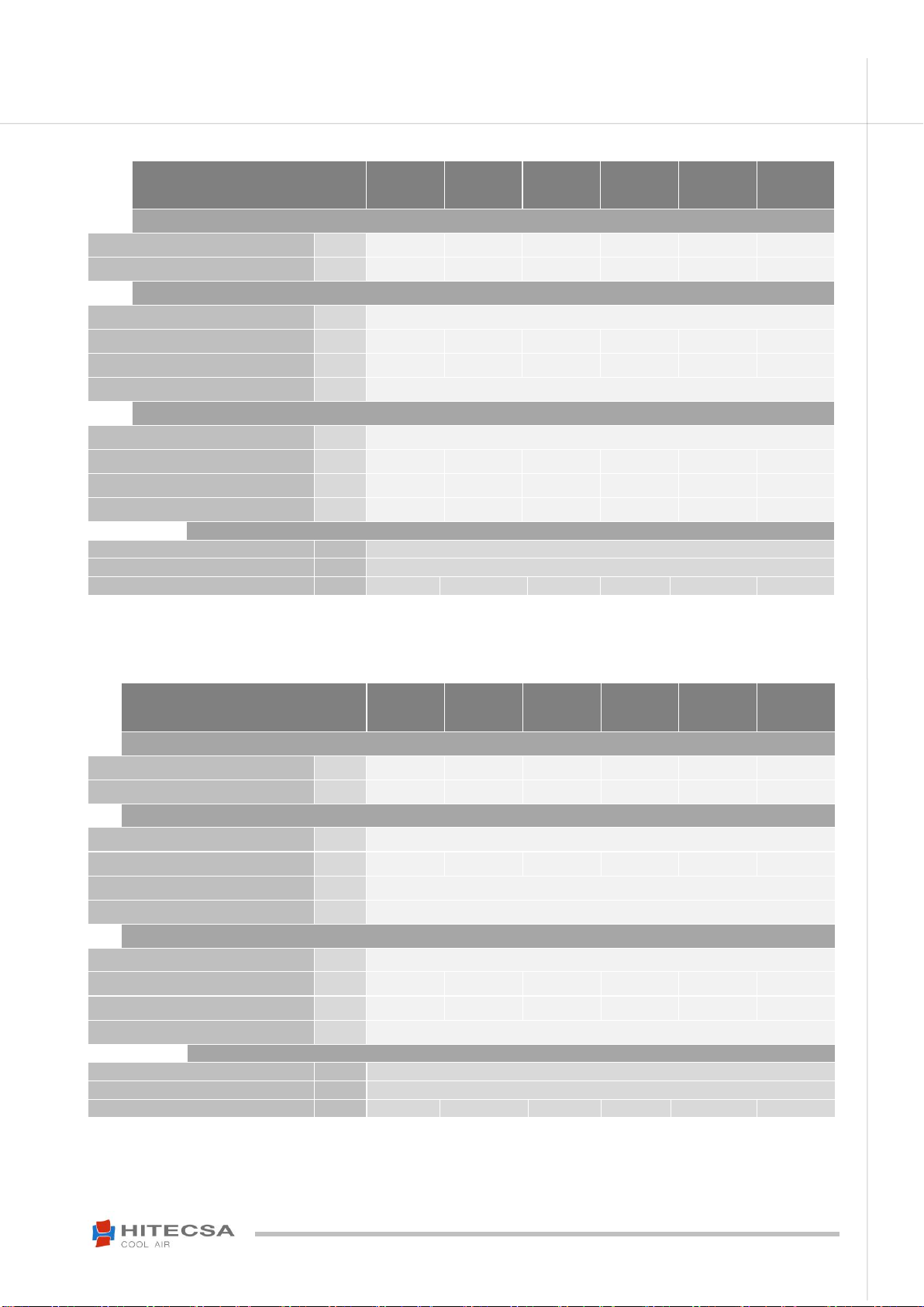
TECHNICAL SPECIFICATIONS
ECHBA-ECHA
201
251
351
371
401
501
CAPACITIES
Cooling capacity (1)
kW
5.6
7.4
9.7
11.6
12.4
14.1
Heating capacity (2)
kW
6.1
8.2
9.8
12.0
13.8
16.4
HEAT EXCHANGER
Type
Coils with aluminium fins and copper tubes
Front surface
m²
0.20
0.25
0.25
0.31
0.31
0.31
Space between fins
mm
2.1
2.1
1.8
2.1
2.1
2.1
Tube diameter
mm
3/8
FAN
Type
Centrifugal. double aspiration
Model
9/7 DD
9/9 DD
10/10 DD
10/10 DD
10/10 DD
10/10 DD
Motor power
kW
0.120
0.250
0.250
0.373
0.373
0.550
Voltage
V
230/1
230/1
230/1
230/1
230/1
400/3+N
REFRIGERANT
Tiype
R410A
Global Warming Potential (GWP) (3)
2088
Charge (4)
-
-
-
-
-
-
(1)
Return temperature: 27°C dry bulb and 19 °C humid bulb, evaporation temperature 7°C.
(2) Return temperature: 20 °C, condensation temperature 40°C.
(3) GWP: Global warming potential (climatic) of 1 kg of greenhouse gas relative to 1 kg of CO2, calculated in terms of 100-year warming
potential.
(4) The charge depends on the outdoor unit and the dimensions of the refrigeration pipes.
ECHBA-ECHA
701
721
751
801
1001
1201
CAPACITIES
Cooling capacity (1)
kW
17.2
18.5
20.8
21.9
28.4
33.5
Heating capacity (2)
kW
18.9
20.4
21.9
24.6
29.8
37.2
HEAT EXCHANGER
Type
Coils with aluminium fins and copper tubes
Front surface
m²
0.47
0.47
0.47
0.54
0.65
0.77
Space between fins
mm
1.8
Tube diameter
mm
3/8
FAN
Type
Centrifugal. double aspiration
Model
12/9 SS
12/9 SS
12/9 SS
12/9 SS
12/12 SS
15/15 SS
Motor power
kW
0.735
0.735
0.735
0.735
1.500
2.200
Voltage
V
400/3+N
REFRIGERANT
Tiype
R410A
Global Warming Potential (GWP) (3)
2088
Charge (4)
-
-
-
-
-
-
(1)
Return temperature: 27°C dry bulb and 19 °C humid bulb, evaporation temperature 7°C.
(2) Return temperature: 20 °C, condensation temperature 40°C.
(3) GWP: Global warming potential (climatic) of 1 kg of greenhouse gas relative to 1 kg of CO2, calculated in terms of 100-year warming
potential.
(4) The charge depends on the outdoor unit and the dimensions of the refrigeration pipes.
8
IOM_ECHBA-ECHA_201a1201_208035_191200_EN
ECHBA-ECHA
EVAPORATION UNITS AIR-AIR
TRANSPORT & RECEPTION
INSPECTION AT RECEPTION
It is advisable to examine the equipment carefully at the time of its reception.
Check that the equipment has not been damaged during transport and it has been supplied complete with all
parts specified in the order and/or with the options specified in the order. If this is not the case, contact the
transport company immediately. (First 48h).
Verify the correct voltage of the nameplate and make sure it is in accordance with local power supply.
In case of any flaw or anomaly detected, please contact HITECSA.
RIGGING
Before moving the unit, make sure that all panels are well fixed.
Raise and set down the equipment carefully.
Do not tilt the unit more than 15 degrees during transportation.
Always transport the unit in its original packaging to the place of installation.
All units come with a particular rigging diagram of that model, similar to the one shown below. Be sure to hoist
the machine through the points indicated in the diagram.
Make sure that the unit is balanced, stable and without any deformations when it is lifted.
STORAGE
If the equipment is going to be stored before the installation, please follow the instructions belowin order to avoid damages,
corrosion or deterioration:
Move it carefully.
Do not place the machine in places exposed to ambient temperature above 50ºC and preferably keep the unit away
from direct sunlight.
Avoid placing the unit with plastic wrapping protection under the sun, as the pressure of the circuits could reach values
that could lead to the intervention of the safety valves.
In addition, when cooling, water condensation occurs inside the machine and the plastic wrap.
Avoid placing other objects on top of the unit (unless it is done within the limits of the overlap planes indicated on the
packaging, etc. Follow these indications).
Avoid prolonged storage, before installation, water inlet, dust and objects in general due to invasion or biological,
meteorological and/or human interactions.
Minimum storage temperature: -10ºC.
Maximum relative humidity: 90%

9
IOM_ECHBA-ECHA_201a1201_208035_191200_EN
ECHBA-ECHA
EVAPORATION UNITS AIR-AIR
INSTALLATION
INSTALLATION LOCATION
- Consult and respect the rules and local regulations which regulate the installation of air conditioning systems.
- Choose a site without dust and debris.
- Respect the appropriate service area for the equipment which will be installed.
- Verify that the ground or structure on which the unit will be installed is able to support its weight in operation.
- Fit shock absorbers throughout the installation to prevent the transmission of noise and vibration.
- Check that the direction of the sound level is not going to disturb anyone.
UNIT SETTLEMENT
Make sure that the unit is correctly levelled.
The bed frame should have the area and the strength to support the weight of the unit.
Be sure that after settlement the unit drain is working properly.
SERVICE AREA (mm)
Make sure to respect the following measurements for the correct operating of the unit.
WEIGHT DISTRIBUTION (kg)
ECHBA
1
2
3
4
TOTAL
201
13.00
13.00
13.00
22.00
61.00
251
14.75
14.75
15.15
25.30
70.00
351
17.25
17.25
17.25
29.25
81.00
371
19.00
19.00
19.00
32.00
89.00
401
21.00
19.00
19.00
30.00
89.00
501
23.25
23.25
20.85
28.65
96.00
701
33.75
33.75
29.50
39.00
136.00
721
33.75
33.75
29.50
39.00
136.00
751
34.75
34.75
29.00
38.50
137.00
801
34.75
34.25
29.00
38.50
137.00
1001
33.00
33.00
28.00
46.00
140.00
1201
36.00
36.00
30.80
51.20
154.00

10
IOM_ECHBA-ECHA_201a1201_208035_191200_EN
ECHBA-ECHA
EVAPORATION UNITS AIR-AIR
INSTALLATION
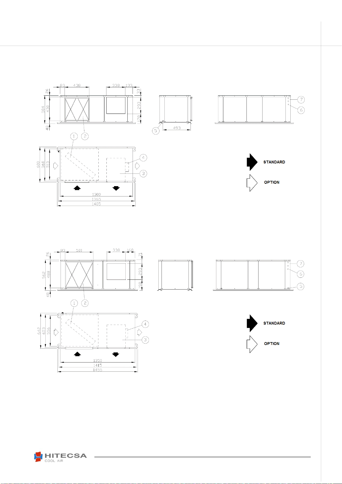
DIMENSIONS
Modelo ECHBA-ECHA 201
Modelo ECHBA-ECHA 251
LEGEND:
1. Coil
2. Air filter
3. Fan
4. Fan motor
5. Drain Ø ¾”
6. Electrical inlet
7. Refrigerant pipe
LEGEND:
1.Coil
2. Air filter
3. Fan
4. Fan motor
5. Drain Ø ¾”
6. Electrical inlet
7.Refrigerant pipe
11
IOM_ECHBA-ECHA_201a1201_208035_191200_EN
ECHBA-ECHA
EVAPORATION UNITS AIR-AIR
INSTALLATION
DIMENSIONS
Model ECHBA-ECHA 351
Models ECHBA-ECHA 371 –401 –501
LEGEND:
1.Coil
2. Air filter
3. Fan
4. Fan motor
5. Drain Ø ¾”
6. Electrical inlet
7.Refrigerant pipe
LEGEND:
1.Coil
2. Air filter
3. Fan
4. Fan motor
5. Drain Ø ¾”
6. Electrical inlet
7.Refrigerant pipe

12
IOM_ECHBA-ECHA_201a1201_208035_191200_EN
ECHBA-ECHA
EVAPORATION UNITS AIR-AIR
INSTALLATION
DIMENSIONS
Models ECHBA-ECHA 701 –721 –751 –801
Model ECHBA-ECHA 1001
LEGEND:
1.Coil
2. Air filter
3. Fan
4. Fan motor
5. Drain Ø ¾”
6. Electrical inlet
7.Refrigerant pipe
LEGEND:
1.Coil
2. Air filter
3. Fan
4. Fan motor
5. Drain Ø ¾”
6. Electrical inlet
7.Refrigerant pipe

13
IOM_ECHBA-ECHA_201a1201_208035_191200_EN
ECHBA-ECHA
EVAPORATION UNITS AIR-AIR
INSTALLATION
DIMENSIONS
Model ECHBA-ECHA 1201
DRAINAGE
The indoor unit drainage (condensate water) has a 3/4” MPT connection.
Condensate drain pipe diameter should be equal or larger than the unit drain connection depending on the line length
and general building configuration.
The drainage line should inclined a minimum 2% for proper water evacuation.
When drain line is exposed to temperatures below 0 degrees, it is necessary to cover with thermal insulation or electrical
heating wire to avoid water freezing and tube damages.
It is convenient to install the water drain trap with proper dimensions (see diagram).
Recommended water drain trap
measures
LEGEND:
1.Coil
2. Air filter
3. Fan
4. Fan motor
5. Drain Ø ¾”
6. Electrical inlet
7.Refrigerant pipe

14
IOM_ECHBA-ECHA_201a1201_208035_191200_EN
ECHBA-ECHA
EVAPORATION UNITS AIR-AIR
INSTALLATION
AIR DUCTS
Air duct dimensions will be determined according to the airflow and available pressure of the unit.
Ducts must be designed by qualified technical people.
Use ducts made of non-inflammable materials in order to avoid any risk of fire as a consequence of the
deflagration of gases. It is advisable to use metal sheet duct with insulation.
Use flexible ducts to connect air ducts into the unit and thus avoid vibration and noise transmission.
DESIGN OF THE REFRIGERANT PIPES
Please refer to the instructions stated in the condenstion unit.
ELECTRICAL INSTALLATION
Unit power supply should be within 10% of volts indicated on the unit nameplate. Damage caused by the start-up
of the unit in an incorrect voltage line is not covered by Hitecsa’s warranty.
When making electrical connections always use the unit wiring diagram.
The line protection elements have to be placed by the installer according to the current legislation local laws.
Must check that the crankcase heater is working prior the start of the unit.
The interconnecting wires have to be located in the protection tube or inside the groove cannel.
Electrical data
ECHBA-ECHA
201
251
351
371
401
501
Power supply
V/~/Hz
230/1/50
230/1/50
400/3+N/50
400/3+N/50
400/3+N/50
400/3+N/50
Max. operation current
A
1.6
1.5
1.9
2.6
2.7
1.6
ECHBA-ECHA
701
721
751
801
1001
1201
Power supply
V/~/Hz
400/3+N/50
400/3+N/50
400/3+N/50
400/3+N/50
400/3+N/50
400/3+N/50
Max. operation current
A
2.0
2.0
2.1
2.3
3.0
4.8
Disconnect main switch from main power supply before starting any type of operations.
WARNING!

15
IOM_ECHBA-ECHA_201a1201_208035_191200_EN
ECHBA-ECHA
EVAPORATION UNITS AIR-AIR
INSTALLATION
ELECTRICAL INSTALLATION
Electrical connections
For further information please refer to the user manual and to the electrical diagram.
Legend:
1. Magnetothermal circuit breaker (D curve) + differential.
2. Optional electrical heater supply.
3. Optional regulation for electrical heater of 1 or 2 stages (2 or 3 cables).
4. Fan power supply 400V.3~+PE or 230V.1~+N+PE depending on the models.

16
IOM_ECHBA-ECHA_201a1201_208035_191200_EN
ECHBA-ECHA
EVAPORATION UNITS AIR-AIR
OPERATION
BEFORE START UP
Start up has to be performed by a qualified service personnel in air conditioning.
Make sure that panels are firmly secured with screws.
Check that there is no leakage of oil or refrigerant.
Ensure that the unit is evenly leveled.
Check if there is enough space for operation and maintenance.
Before opening the electrical panel and having access to the inside of the machine it is MANDATORY to
disconnect the power supply hose of the machine which MUST BE FREE OF VOLTAGE for this operation.
Check that the drainage is not blocked.
Always use the electrical diagram of the unit to make the connections.
Make sure that all electrical connections are properly tight.
The power supply of the unit must be as indicated on the serial plate. Damage caused by the start-up of the unit
in an incorrect voltage line is not covered by Hitecsa’s warranty.
The unit must not be supplied with any other voltage than that the indicated on the serial plate. The power supply
to the unit must be within 10% of the voltage indicated on the serial plate.
Check the correct rotation direction of the fans.
The installer must place line protection elements in accordance with current legislation.
Wiring of electrical connections must be protected by a tube or other cable conduits.
Make sure if the crankcase heater of each compressor has been operating during 24 hours prior the start up.
Check that the air filters are clean and correctly fitted.
Check the condition and placement of grilles, diffusers, air ducts, tarpaulins, etc.
START UP
It is necessary to take notes of the air inlet and outlet temperatures to the internal coil, the volts and amps of the
compressor and motor fan, as well as the suction and discharge pressure of each compressor.
It should be remembered that it is necessary to clean the air filters after the first 4 hours of operation.
Observe, at least, 3 cooling cycle operations.
Due to the unit has frequency converters, it is essential that the protection be at least 300mA to prevent power
cuts caused by the activation of the circuit breaker.

17
IOM_ECHBA-ECHA_201a1201_208035_191200_EN
ECHBA-ECHA
EVAPORATION UNITS AIR-AIR
OPERATION
INDOOR FAN TRANSMISSION ADJUSTMENT
Adjust transmission in such a way that the indoor motor consumption comes to its normal value.
If consumption is below nominal value it means that unit air flow is too low.
To change fan speed:
1. Remove the belt. Move the motor along its track (or loosen the tensor set screw) in order to release it.
2. Loose the set screws of the motor pulley and turn the movable flange. Open of close depending on the needs
(Open: speed decreases).
3. Tighten set screws.
4. Place the belt in the pulley cannel. The closure of opening of the pulley could void the size of the prior belt. In
this case, replace it for other belt of the same profile and with the appropriate length.
5. Tighten the belt by using tensor screw or sliding the motor, depending on the case.
-Align fan and motor pulleys:
1. Loose fan pulley set screws.
2. Slide fan pulley along the shaft and align with motor by using a ruler in order to ensure that is parallel to the belt.
3. Tighten fan pulley set screws.
- Adjust belt tension:
1. Loose motor mounting plate bolt and slide it.
2. Belt flexion in millimeters is estimated by dividing S by 40.
1. Motor
2. Motor pulley
3. Transmission belt
4. Fan pulley
5. Tensor set screw
6. Set screw
7. Fixed flange
8. Movable flange
18
IOM_ECHBA-ECHA_201a1201_208035_191200_EN
ECHBA-ECHA
EVAPORATION UNITS AIR-AIR
OPERATION
FAN TRANSMISSION ADJUSTMENT
Adjust transmission in such a way that the indoor motor consumption comes to its normal value.
If consumption is below nominal value it means that the unit air flow is too low.
MODELS
Nominal
Pulley
Correa
Open
kW
A
Fixed
Variable
ECHBA 501
0,55
1,59
150 E20 1A
100/125 E19 1A
A-42
0
ECHBA 701
0,74
2,00
150 E25 1A
75/100 E19 1A
A-43
1
ECHBA 721
0,74
2,00
150 E25 1A
75/100 E19 1A
A-43
1
ECHBA 751
0,74
2,00
150 E25 1A
75/100 E19 1A
A-43
1
ECHBA 801
0,74
2,00
150 E25 1A
75/100 E19 1A
A-43
0
ECHBA 1001
1,50
3,00
160 E25 1A
100/125 E24 1A
A-45
2
ECHBA 1201
2,20
4,80
160 E25 2A
100/125 E28 2A
A-46
2
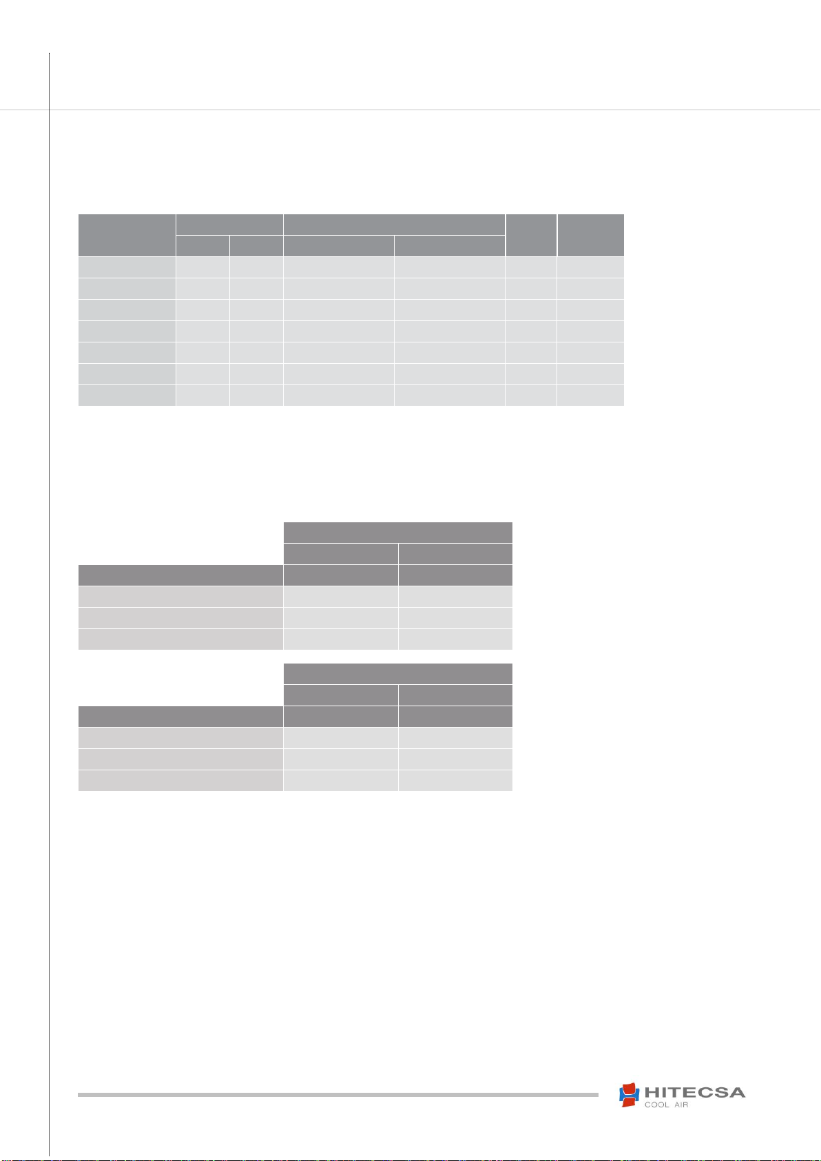
OPERATION LIMITS
AMBIENT AIR TEMPERATURE
DRY TEMP.
HUMID TEMP.
COOLING CYCLE
ºC
ºC
Standard conditions
27
19
Minimum conditions
21
15
Maximum conditions
32
21
AMBIENT AIR TEMPERATURE
DRY TEMP.
DRY TEMP.
HEATING CYCLE
ºC
ºC
Standard conditions
20
–
Minimum conditions
20
–
Maximum conditions
26
–

19
IOM_ECHBA-ECHA_201a1201_208035_191200_EN
ECHBA-ECHA
EVAPORATION UNITS AIR-AIR
MAINTENANCE
It is advisable to do maintenance works every 1.000 operating hours as well as at the beginning of each cooling season.
In case of leakage, any manipulation and / or recovery of refrigerant must be carried out by qualified and accredited
personnel in the current regulations.
CONSERVATION AND CLEANING
Electrical circuit: Make sure that all electrical connections -wires, contactors and terminals- are properly tight. Record the
readings for volts and amperes of each compressor and fan motor. Verify the starting current. Check the good operation
of all relays, pressure switches and phase sequence relay of Scroll compressor.
Coils: At least once a year, clean condenser coils with water and detergent, then dry with air at a low pressure. Never
clean with wire brush.
Fans: Check the direction of rotation of the fans. Examine the support of the fans. Check the operating status.
Before handling the fan, make sure that it is disconnected from the main power, even if it is already stopped and that
nobody can start it during the intervention.
- It is necessary to make a regular inspection of the unit. Its frequency must be based on the working conditions to avoid
the accumulation of dirt in propellers, turbines, motors and grids that could entail risks and shorten its life.
- Be very careful not to unbalance the propeller or the turbine in cleaning operations.
- Must observe the current safety legislations of each country in all maintenance and repairing works.
Motors and fans do not need any additional lubrication.
Transmission belts: Check the status and the tension of the transmission belt, at least twice the first operating month,
after every 1000 operating hours.
Drainage system: Verify condition and good operation of the drainage tray and the drain trap.
Air filters: Clean filters after the first operating hours to collect possible light materials such as papers, pieces of porexpan,
etc. left over from the installation and that have been dragged through the air circulation. Clean again every 3 months (or
more often according to its operation). The filter can be cleaned with soapy water, after rinse it with clean water and let
dry. If necessary, replace filters before they are in bad conditions (check current legislation of each country, EN 779, UNE-
EN 13053…).
Before performing any service or maintenance operation it is mandatory to turn off the main
power switch of the system to avoid any personal injuries. Locked it so that nobody other
than a qualified technician can switch on electrical power
WARNING!

20
IOM_ECHBA-ECHA_201a1201_208035_191200_EN
ECHBA-ECHA
EVAPORATION UNITS AIR-AIR
Subject to modifications without prior notice.
This manual suits for next models
23
Table of contents
Other HITESCA Heat Pump manuals


