Section 3: InstallationPage 6
3 INSTALLATION
3.1 GENERAL
This section gives details of the installation process for the Grant
Combined volumiser/low loss header with backup immersion
heater.
These installation instructions must be read in conjunction with
the Grant Aerona³ air source heat pump installation instructions
(provided with the heat pump).
Before starting any installation work on the Grant Aerona³ air
source heat pump and volumiser/low loss header, please read the
Health and Safety information given in Section 14 of the Aerona³
Installation Instructions.
3.2 REGULATIONS AND STANDARDS
The installation of the Grant Aerona³ air source heat pump and
the volumiser/low loss header must be in accordance with the
following recommendations, as applicable:
• Building Regulations for England and Wales, and Building
Standards for Scotland
• Local Bylaws (check with the Local Authority for the area)
• Water Supply (Water Fittings) Regulations 1999
• MCS Installer Standards (if applying for the Renewable Heat
Incentive)
• MIS3005 Requirements for contractors undertaking the
supply, design, installation, set to work, commissioning and
handover of microgeneration heat pump systems.
• MCS020 MCS Planning Standard
The installation should also be in accordance with the latest
edition of the following standards and Codes of Practice:
• BS7671 and amendments
• BS EN 12831
3.3 LOCATION
The Grant Combined volumiser/low loss header can be mounted
on any suitable wall surface capable of carrying the weight of the
unit when full of water and where the required clearances can be
achieved.
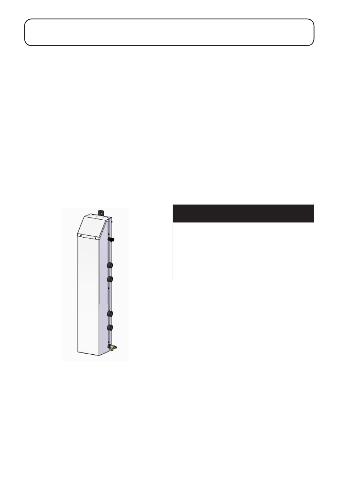
The unit MUST be installed vertically, with the immersion heater at
the top, as shown in Figure 2-1.
It MUST only be installed inside a property, and not located
externally, as it not designed to be weatherproof.
! NOTE !
The Grant volumiser/low loss header MUST NOT be
installed externally.
3.4 CLEARANCES
The Grant Combined volumiser/low loss header must be installed
such that adequate clearance is available for maintenance. In
particular, a suitable clearance of 300mm must be available
immediately above the unit to allow the removal and replacement
of the electric immersion heater.
Suitable clearance should also be allowed on the right-hand side
of the volumiser/header for access to, and the use of, the air
vent, drain cock, and any system isolating valves, as and when
required.
3.5 UNPACKING
The Grant Combined volumiser/low loss header is supplied
wrapped in bubble wrap with a separate kit of components
in a plastic bag located inside the top cover. Refer to list of
components given in Section 1.3 of these Instructions.
! NOTE !
Take care if cutting the bubble wrap with a knife not to
damage the volumiser/low loss header casing immediately
beneath.
3.6 INSTALLATION PROCEDURE
To install the Grant Volumiser/Low Loss Header:
1. Using a suitable thread sealant, t the ⅜” x ¼” reducing bush
into the ⅜” socket at the top of the right-hand side of the
volumiser/header and then t the ⅜” manual air vent into the
reducing socket. Refer to Figure 2-1. Position the air vent
such that the outlet is pointing downwards.
2. Again, using a suitable thread sealant, t the drain cock into
the ½” socket at the bottom of the right-hand side of the
header/volumiser. Refer to Figure 2-1. Position the drain cock
such that the outlet is facing downwards.
3. Position the volumiser/header with the back against the wall
on which it is to be mounted and mark the two xing centres
from both the top and bottom xing brackets.
4. Note that when lled with water, the volumiser/header will
weight 30kg. Ensure that the wall concerned is structurally
capable of carrying this weight.
5. Drill the wall to take suitable wall xings (not supplied) for
the type of wall construction and the weight of the volumiser/
header when full of water and t the wall xings.
6. Re-position the volumiser/header against the wall, align the
holes in the top and bottom xing brackets with the two wall
xings, and secure the header/volumiser to the wall with
screws.
! WARNING !
The immersion heater must NOT be used unless it is fully
immersed in water.
Always ensure that the volumiser/low loss header is full of
water BEFORE switching on the electrical supply.
3.7 HEAT PUMP FLOW AND RETURN
CONNECTIONS
The heat pump ow and return connections can be made to either
the right-hand or left-hand connections of the Grant Combined
volumiser/low loss header, but BOTH connections must be made
to the same side. Refer to Figures 3-1 and 3-2 for connection
details.
A second heat pump can also be connected to the volumiser/
header, but it must be connected to the same side as the rst heat
pump.
This second heat pump will operate as a ‘supplementary’ unit
controlled from the other ‘lead’ heat pump. Refer to Section 5 of
these instructions for the required parameter settings for both heat
pumps for this control conguration.
All unused connections should be sealed using the brass blanking
plugs provided.