CS THERMOS INSERTO SKYLINE User manual

cod. 6118060 09-2013
Via Padania, 35 - 31020 S. Vendemiano (TV), ITALIA
INGLESE
INSERTO SKYLINE
INSTRUCTION MANUAL

ENGLISH
1
CS THERMOS
You have just purchased a high quality product produced entirely in Italy.
Reading this manual is very important to guarantee correct functioning of the product in regards to
safety and servicing of the machine.
A correct installation and initial set up of set up parameters is vital and therefore it is reserved for
technicians authorized y the manufacturer as is periodic maintenance.
Cleaning is an important element for safety maintenance and for product functioning, and must e
carried out periodically to guarantee a long life and for keeping people and the machine safe.
INDEX
1 Safety warnings ............................................................................................................................ 2
2 Product description ................................................................................................................... 3
3 Pellet qality .................................................................................................................................... 3
4 Si e data.......................................................................................................................................... 4
5 Technical data............................................................................................................................... 5
6 General rules for the reali ation of the flue........................................................................ 6
7 Execution of smoke discharge ................................................................................................. 7
8 Installation .................................................................................................................................... 8
9 Electrical connection ................................................................................................................ 9
10 Preliminary checks for the first start up ........................................................................... 10
11 Upper flue gas outlet ................................................................................................................. 10
12 Control panel display.................................................................................................................11
12 Operational phases ....................................................................................................................11
14 Programming .............................................................................................................................. 12
15 Alarm codes ................................................................................................................................. 14
16 Care and maintenence ............................................................................................................. 15
17 Sliding guides kit........................................................................................................................ 18
18 Kit Inserto Fuocovivo .............................................................................................................. 21
19 Kit assembly Inserto Confort ............................................................................................... 24

ENGLISH
2
1. SAFETY WARNINGS
Do NOTuse fuels that are different from those instructed by the manufacturer.
DO NOT use any flammable liquid to light the stove.
DO NOT light stove if glass is damaged and do not, for any reason, open the fire box door while
operating.
Only clean the glass when the stove is cold, using a specific cleaning detergent with a cotton
cloth or paper towels.
The machine must ONLY be installed by qualified personnel, certified in conformity with current
rules and regulations.
DO NOTunplug the stove if there are flames in the fire pot.
When the stove is running, pay particular attention to: the hot parts (glass, handle, etc...) they may
cause burns. Keep out of reach ofchildren.
Remove power from the machine before any kind of maintenance or cleaning.
DO NOTplace hands inside the tank during functioning.
Never throw unburnt pellets into the tank: it is a fire hazard.
Never throw pellets manually into the fire pot, especially if there are flames or hot ashes.
Unpleasant smells during functioning may be caused by the type of pellets used.
Possible noises during functioning are normal, caused by the settlement of assembled parts
Store bags of fuel at least 1 metre away from the stove, in a dryand sheltered part of the home.
WARNING: (see UNI10683 standard)
A minimal natural flue draught of 6-8 Pa must always be guaranteed. In case of electric power cutoff or
strong wind conditions, the natural draught avoids overheating of the stove’selectrical componentsand allows
the smoke to get out from the chimney instead of getting into the room.
SPECIAL WARNING
Improper flue draught, excessive humidity in the fuel, or an elevated ash residue in the combustion
chamber may cause THE STOVE TO NOTSTARTAND IS NOT A RESULTOF A DEFECTIVE PRODUCT.
While the stove is running, there may be some small flames on the sides of the burner, this is NORMAL
because gas combustion occurs when incontactwithwarm parts.
In case of ignition failure clean the crucible before restarting the stove.

ENGLISH
3
2. PRODUCT DESCRIPTION
Thisstove model is equipped with a traditional pellet burner to burn only wood pellet, and it is equipped with
an electrical grid for functioning and combustion control, and can modulate their power according to settingsset
from the display, this way allowing better adaptation to heating requirements.
During initial start up phase (approx 10 min) the crucible automatically fills with combustibles, whilst the
resistors heat up and ignite them. After the presence of a flame has been detected by combustion smoke
detectors, normal functioning starts and, thanks to the microprocessor, permits the variation of combustibles
contribution byacting on the auger motor and modulating the flame.
At everypoint the electronic grid controls the temperature sensorsas well as the safetydevices and, in case of
anomalies, it will stop functioning and signal thison the display (see alarm code paragraph).
Room heating is guaranteed by an air flow that isvariable according to functioning power that passesthe tube
sectioning for combustion smoke. For models covered in ceramics or majolica, the thermal exchange in the
room will be warmer and more pleasant
3. PELLET QUALITY
There are various typesand qualities of pellets on the market and it isimportant that the onesyou use are not
of abysmal quality. A poor, cheap qualitypellet could contain glues, resinsor chemical substances that could
seriously jeopardise the functioning and the safety of the product, by inciting blockage of ashes and smoke
discharger, forming corrosive gas, reducing machine performance, release polluting substances into the
atmosphere and window incrustation. Laws in force on the matter state that products that use this type of
combustion have to be fed with good quality pellets that are well compacted and not very powdery. We
recommend that you askyour retailer for suitable pellets that are in compliance with DIN51731 standards or
M7135 standards including any updates
Wooden pellet characteristics should be: of a 6÷8 mm diameter, approx. 5÷20 mm length, have an 8% humidity
and a heating potential of 18200 KJ/Kg.
The manufacturer does not assume any responsibility for use of poor quality pellets and therefore is
non respondent to consequent malfunctioning of the stove..
Store pellets at least 1 metre away from the stove in a dry and shelteredpart of the room.
4.SIZE DATA
INSERTO SKYLINE WITHOUTGUIDES
730mm
320mm
540mm
500mm
550mm
530mm
210mm
60mm
90mm
160mm
160mm
scarico fumi
outoput tube
sortie fumées
ariacomburente
combustion air
air comburante
DIMENSIONE MINIMA DELLANICCHIA
DIMENSIONS MINIMUM DELA NICHE
MINUMUM OVERALL DIMENSIONS OFTHE NICHE
LxPxH= 770mm X 620mm X 550mm
80mm
vista superiore
vue dedessus
top view
vista posteriore
vue arrière
rearview

ENGLISH
4
INSERTO SKYLINE WITH GUIDES
INSERTO SKYLINE WITH GUIDES + FLUE HEADER KIT
770mm
560mm
500mm
570mm
550mm
210mm 90mm
160mm
160mm
scarico fumi
outoput tube
sortiefumées
vista superiore
vue de dessus
top view
vista posteriore
vue arrière
rear view
DIMENSIONE MINIMA DELLA NICCHIA
DIMENSIONS MINIMUM DE LA NICHE
MINUMUM OVERALL DIMENSIONS OFTHE NICHE
LxPxH=790mm X 620mm X 570mm
340mm
80mm
aria comburente
combustion ai r
air comburante
80mm
770mm
560mm
500mm
80mm
570mm
550mm
DIMENSIONEMINIMA DELLANICCHIA
DIMENSIONSMINIMUMDE LANICHE
MINUMUM OVERALLDIMENSIONS OF THE NICHE
LxPxH= 790mm X 650mm X 570mm
kits carico fumi
kits ortie fumées
flue headerki t
2
1
0
m
m
160mm
340mm
80mm
aria comburente
combustion air
air comburante
9
0
m
m
160mm
scaric ofumi
outoput tube
sorti efumées
vistas uperiore
vue de dessus
topv iew
vistaposteriore
vuearrière
rear view

ENGLISH
5
5. TECHNICAL DATA
TECHNICAL DATA
UNIT OF
MEASURE
INSERTO SKYLINE
HEARTH THERMALPOWER kW
3,0÷9,0*
NOMINALTHERMALPOWER kW
2,5÷7,4*
PERFORMANCE %
82*
CO EMISSION ppm
200 max
NOISE dB
<47
COMBUSTIBLE
PELLET
CONSUMMATION AT MAXIMUM POWER Kg/h
max 1,9 **
MAXIMUM AUTONOMY WITH CONTINUOS
FUNCTIONING AT POWER 1 ORE
max 22**
PELLET HOLD CAPACITY Kg
18 ~
HEATING VOLUME m3
150÷220 max ***
DIAMETER OF SMOKEOUTLET mm
80
DIAMETER OF EXTRACTION PASSAGE °C
max 210
ELECTRICAL POWER V
V230~ / 50Hz
MAXIMUM INPUT A
3
AVERAGE INPUT DURING FUNCTIONING W
100
INPUT DURING START-UP W
max 620
OVERALLDIMENSIONS mm
See specific chapter
NET WEIGHT Kg
~96
COVERING
METAL
* Nominal fireplace power and yield are , measured inside a laboratory under optimal installation conditions and testing optimal installation conditions.
** This data was measured through in lab testing under optimal conditions. Hourly consumption may vary base on the type of pellet used and installation.
*** The volume that can be heated is subject to the conditions of stove installation, the type of insulation in the home and the external climate conditions
specific to the geographical location
SAFETY THERMOSTATS
The two safety thermostats are positioned in the upper side of the display. To restore operation to wait for the
stove to cool, unscrew the protective cap and press the reset button. Remove the alarm from the display by
holding down for 3 seconds the off button.

ENGLISH
6
6. GENERAL RULES FOR THE REALIZATION OF THE FLUE
Here are illustrated a few simple yet important rules to follow for the safe construction of the flue (for further
information, please read the UNI10683 regulation)
• The safe and correct functioning of the pellet stove is dependant on the connection to a single and
independent flue. No other fireplace, stove, boiler, aspiring hoods etc... are to be connected to the same
flue (see fig.3).
•This machine needs to expel products resulting from combustion via a vertical flue that has a suction
pressure between 6 and 10 Pa, in order to constantly guarantee the expulsion of smoke, even with the
absence of electric power oradverse conditions.
•The part of the flue that extrudesfrom the roof or remainsin external contact must be covered with tiles or at
least well insulated.
• The stack must be wind resistant, have an internal section that is equal to that of the flue, a useful section at
least twice the size of the flue, and prevent entering of rain.
• Any other building parts, plantsor other obstacles that are higher than the roof must be positioned at least
3m away from the flue.(see fig.4).
• Whenever two flues with parallel exits are used, it is advisable to lift the wind resistant flue (see fig. 5).
The flue section must be uniform, with smooth surfacesthat do not narrow down, and the curvesmust be
regulated, without discontinuity.
It is advisable that the smoke conduct has a solid material and eventual condensation collecting box,
positioned under the smoke conduct intake, so that it is easily accessible and can be inspected from the
airtight door.
Fig.4
Fig.5
SI NO
YES
NO
SI
YES
Fig.3
ENGLISH
7
7. EXECUTION OF SMO E DISCHARGE
Smoke discharge must comply with regulationsin vigour and therefore must happen via the roof and end over
the roof level. The discharge tube must be made out of smooth steel with silicon seal and not be corrugated
flexible type. Furthermore it must be positioned externally and not in closed or semi-closed spaces. For
example: garages, narrow corridors, under closed penthouses or any other placeswhere smoke could collect.
When connecting the stove to a flue, make sure, with a professional chimney sweep, that the flue is perfectly
whole.. Oppositely it isabsolutely obligatory to encase the existing flue with material which is suitable enough
to ensure correct functioning (see fig.7).
TYPE OF TUBES FOR FLUES
Rigid painted steel tubesshould be used, and should be at least 1.5mm thick, alternatively they can be made
out of stainless steel which isat least 0.5mm thick. The male/female coupling collarsmust be superimposed by
at least 40mm. For INSERTO CAMINETTO model use 600°C flexible silicon tubing, with double smooth wall
inside, up until connected to the flue.
FLUE TUBING DIAMETER
The diameter of the tubes depends on the type of system. The stove has been designed for tubes with an
80mm diameter, asshown in the table, howeverin some cases100mm isadvisable. If 100mm diameter tubing
is necessary, connect itto the stove using a "T" pipe connection with a ø80 -ø100 pipe connection (see fig. 8)
FLUE
DIAMETER
ESTIMATIO
N
Length of tube length lessthan 5 mt
80 mm
Correct
Length of tube length more than 5 mt
100 mm
Obligatory
For installationsat an altitude above 1200 mt a.s.l.
100 mm
Recommended
Note: for every 90°curve add 1m andfor every 45° add 1/2m. Thelengths indicatedonthe tableare relevant for vertical tubing.
Horizontal parts must not be longer than two metres.
It is obligatory to use a "T" connection tube (see fig.8) with an inspection plug, as a connection between the
stove and the flue, which will allow both the collection of ash that is deposited inside the tubes and periodical
cleaning of the flue, without the need to dismantle. Seeing that the smoke isunder a light pressure, ensure that
the plug for cleaning the flue hasa tight fitting and that it remainsso after cleaning. Remember to fix it back as
it was and check the conditionsof the seal. Check that the connectionsbetween various tubes are in order, as
indicated by the manufacturer.
It isstronglyadvised not to place tubes horizontally, but if absolutely necessary make sure they are placed with
an angle of at least 5°.
If a traditional flue is used it is possible to connect without the need for a "T" connection tube, but you must
checkthat the flue hasa box for collecting ash.
It isadvisable to connect to the stove with a horizontal track that is not more than 1m long.
If the lengthsof the tubesare correct the flue should have a suction pressure between 10 and 15 Pa.
Do not change sectionsof tubing half way and above all after a bend or a horizontal tract. Checkthat there is
no narrowing in the tubing or the flue.
ISOLATION AND DIAMETER OF HOLES IN WALLS OR ONTHE ROOF
Once the position of the stove isestablished and that you have checked that the place of installation is ideal, it
is then necessary to make the hole for passing tubesthrough the wall. Thiscan vary according to the type of
installation, the diameter of the tube and the type of wall or roof where the hole is made.
N.B.: if the floor can not support the weight of the stove, position a sheet platform of the correct size with
insulation applied on the floor (rockwool) and with a nominal density greaterthan 80kg/mc

ENGLISH
8
END PART OFTHE FLUE SYSTEM
The stack must not be installed in spaces that are closed, poorly ventilated or, in general, where smoke can
collect.
It isnecessary to checkthat there are no flammable elements(plants, wood) or elements that could be visually
damaged (walls, windows) within 3m of the flue.
WARNING: Seeing that regulations regarding installation of pellet fuelled stoves are constantly being
updated, ask ones installer for eventual changes.
8. INSTALLATION
1- Prepare the support base of the niche perfectly flat, having the bottom in cement or concrete/beton and
suitable to support the weight.
2- Place the device on the base of the niche and slide it backup to approach the flue pipe gas outlet previously
installed.
3- To connect the flue pipe gas outlet remove the predisposition on the top right of the device (see figure)
unscrewing the fixing screw. Put your hand up to the flange off lue gas outlet and accompanythe movement
of the tube graft spingendo l’apparecchio all’interno della pushing the device within the niche.
4- The insert is arranged in the front part below the fireplace door with an opening for ventilation. If it is
necessary for reasons of space, you can remove the two omega side unscrewing the screws.
It is mandatory to prepare in this case the aeration openings in the housing niche.
Perform this operationwhen the stove is off and cold, in the absence ofelectrical voltage.
The niche housing must be provided with at least two openings of 120cm2 arranged in a lower
part and one in the upper part to allow the correctventilationand air intake for combustion.
Fig.7
Fig.8
Raccordo 80-100
Raccordo a "T"
Ø 80
Ø 100
DIREZIONE DI
PULIZIA
CLEANING
DIRECTION
JOINT
“T”
JOINT
ENGLISH
9
If you are using the sliding guides kit remove the two omega support on the sides of the inserto.
Do not install the device within a niche made up of flammable material.
Provide a minimum clearance of 2 cm free all around the set
9. ELECTRICAL CONNECTION
All machines are equipped with power cables, for which, in case of the need for replacing, an authorized
technician must be used.
Before connecting to the power supply, checkthat:
•the electric plant has been fitted with a 6A magneto thermal switch
•The characteristics of the plant are sufficient enough to satisfy what is indicated on the machine
characteristic plaque (electric power, nominal voltage etc...)
•The plant hasa sufficient earth connection according to nominal regulationsin vigour (earth connection is
obligatory by law)
•The power cable should never, at any point, overheat 50°C above room temperature: If a direct connection
is desired, it isnecessary to use an omni polar switch, with a minimum opening between contactsof 3mm,
that has been designed for the electrical charge indicated on the plaque and must correspond to regulations
in vigour.the earth wire, brown/green, should not be interrupted by the switch! The plug oromni polar switch
should be easilyaccessible once the machine hasbeen installed.
In case ofa prolonged disuse of the machine, disconnect the power supply.
The manufacturer declines any responsibility if what stated above or in actual anti-injury laws are
not respected.
INTERNAL ELECTRICAL PLAN
DISPLAY
L
N
PRESS
+FUMI- T. CALD.
FU MI
V. AMB.
POWER SUPPLY
230V - 50Hz~
ELECTRICAL
RESISTORS
GAS SAFETY
THERMO STAT
AUGER SAFETY
THERMO STAT
PELLET LOADING
AUGER MOTOR
AIR PRESSURE
SWITCH
FUSE
4 A
PROG RAMMING
PORT
FUMES FAN
ENCO DER
CLOCK
BATTERY
FLUE GAS
MOTOR HEATING FAN
MOTOR
GAS
PROBE
ROOM
PROBE
ENGLISH
10
10. PRELIMINARY CHEC S FOR THE FIRST START UP
OBLIGATORY GUIDE LINES FORTHE SAFETY OF PEOPLE; ANIMALS AND OBJECTS.
The following information is about a number of obligatory general regulations for a correct instalment, and is
intended for the installer.
• It is recommended to place insulation between the floor and the touching points of the machine with a
sheet at least 2mm thickand a diameter at least 50mm greater than the area occupied by the machine, if
the stove is installed on top of a wooden floor.
• The flue tubing must have a diameterof at least 80mm.
• Leave a space of at least 50 mm between the outer sheeting of the stove and the wall in order to ensure
correct airintake of the air that will go on to be heated by the stove, and also to allow easy removal of the
air filter for cleaning.
•Should the machine be installed close to flammable walls, keep a safe distance of 30cm from the rear and
sides of the machine. Avoid leaving any type of flammable or combustible materialswithin 1m of the heat
waves from the glass window situated on the front of the machine. If installed on a floor made out of
flammable material place a sheet at least 3mm thick, 30cm away from the front of the machine and 10cm
form the side.
•For built in installation of ECONOMICA model in contact with flammable materials, place all around the
frame of the plate and the material, an insulating sheet at least 20mm thick. Should there be a shelf
positioned above the plate, made out of flammable material, keep a distance of at least 60cm.
•For the INSERTO model, neverinstall the machine with built in flammable material.
•Checkfor a correct level of combustible load inside the crucible.
•For the ECONOMICA model, remove oil residuesthat protect the upper plate.
For the first few minutesthat the machine operates (for the first time)it maybe possible to smell paint:
this isnormal. Aerate the room with the machine operational.
11. UPPER FLUE GAS OUTLET
The stove is supplied asstandard with the rear flue gas outlet but it ispossible to carry it in the upper part by
reversing the two flanges, according to figures below.
- Breakthe preparation/predisposition at the top of the device using a hammer.
-
Invert the position of the flange with the flue connection in place of that blind (fig.A) making sure that it
complieswith the direction of the assembly (fig. B,C) and tightened the screws.
PAY ATTENTION TO THE ASSEMBLY WAY OF FLANGES WHEN CARRING OUT THE UPPER
FLUE GAS OUTLET
FIG. A
FIG. B
FIG. C
ENGLISH
11
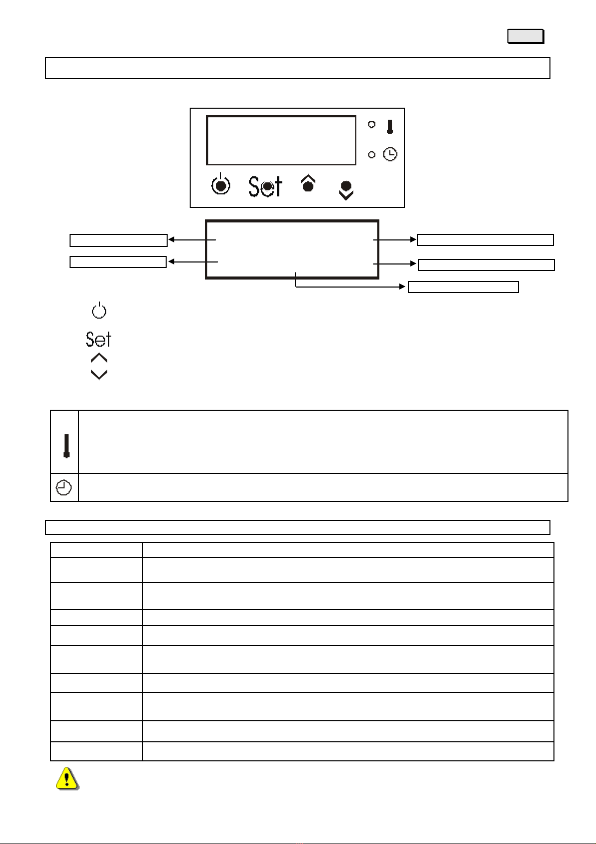
12. CONTROL PANEL DISPLAY
DESCRIPTION OF DISPLAY BUTTONS
Key - turns the stove on and off in manual mode (holding itfor 2 seconds), eliminatesalarmsand exits
programming
Key - changesthe screen and confirmsset data
Key - key for increasing valuesbeing set
Key - key for decreasing values being set
MEANING OF LED LIGHTS
When the led if "permanently" onitmeans thatonce the set room temperature has been reachedit will stayonat
thelowest setting.
The "blinking"led communicates that once the set room temperaturehasbeen reached the stove will turn off.
When the led isturned off itmean the set room temperature hasbeen reached.
When the led isturned on it meansthat hourlyprogramming forautomatic operation hasbeen set.
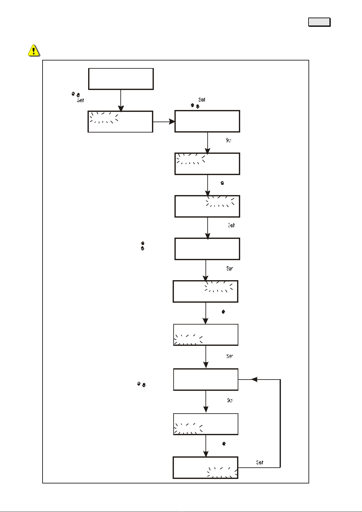
13. OPERATIONAL PHASES
DISPLAY MEANING
Clean.
Pre-ventilation and safety controls phase, with fire pot cleaning before loading fuel.
Charged
Start-up phase with fuel load in the burner while supplying power to the resistorsat the
same time.
Pause
Pause while awaiting flame.
St. Fire
Waiting phase during which the start-up must take place.
Stabil.
Stabilization phase, after the flame hasstarted, with a medium size load of fuel.
Fire
Burneroperational adjustment phase where power can variesfrom 1 to 6
Turn off
Timed turn off phase associated to an interruption in the fuel for fire pot cleaning and
waiting for the flame to be totally extinguished.
Off
Turned off status until there is an following request forheat
Stand by
Turn off because room temperature hasbeen reached
IN CASE OF AN ALARM, WAITFOR THE END OF THE TURNING OFF PHASE
Set
Set day and
time
Operational
Room temperature recorded
Room temperature requested
Operational power
Mer 09:00 20,0°C
Accesa 5 25,0°C

ENGLISH
12
14. PROGRAMMING
MAIN SETTINGS
Use the keys as instructed to access the desiredsetting
Use onlywood pellets as fuel.
Before selecting the type of fuel to be used in the display ensure that you have introduced
the same type of fuel in the tank.
Sun 09:00 20,0°C
T. room
Hours
Ignition
Function
Combustible Combustible
Pellet1
Heating air Heating air
Trigger
T. room
Da of the
Trigger
Off 5 25,0°C
ESC SET
ESC SET
ESC SET
ESC SET
ESC SET
ESC SET 01
modulation YES
25,0°C
week Sun
timer YES
E SC
ON0 0: 00 OF F00 :0 0
Load
Load
ESC SET
- _ _ _ 0 _ _ _ +
00:00
See specific
chapter
Hors
Tim er0 1 mtw tf ss
ENGLISH
13
AUTOMATIC START-UP PROGRAMMING
Turning off for each time slot must not terminate after 23:59 of that day
Activate
Timer01 mtwtfss
Timer02 mtwtfss
Timer02 mtwtfss
Timer02 mtwtfss
Timer02 MTWTFss
Timer02 MTWTFss
Timer02 MTWTFss
Timer02 MTWTFss
Timer02 MTWTFss
Timer02 MTWTFss
timer yes
ON00:00 OFF00:00
ON00:00 OFF00:00
ON00:00 OFF00:00
ON00:00 OFF00:00
ON00:00 OFF00:00
Press to modify
Press to modify
Press to modify
Press to modify
Press to modify
Press to modify
Press to modify
Press to modify
Press the key to confirm
Press the key to modify
Press the key to modify
Pressthe key to confirm
Press the key to confirm
Press the key to confirm
Pressthe key to confirm
Press the key
ON00:00 OFF00:00
ON00:00 OFF00:00
ON08:30 OFF00:00
ON08:30 OFF00:00
ON08:30 OFF00:00

ENGLISH
14
15. ALARM CODES
For your own safety do not tamper or modify any of the machine's components: the
manufacturer does not guarantee the normal operation, that as a result may be very dangerous.
In case of malfunctioning, difficulties, or whenever a safety device is activated, it is important to
contact authorised personnel. All operations must take place when the stove is coldand disconnected
from the power supply.
DISPLAY MEANING
Motor flue gas
Non working fumes motor: contact an authorised technician
1 heat.elem.KO One of the resistorsisnot working: contact an authorised technician
2 heat.elem.KO Both resistorsare not working: contact an authorised technician
heat.element KO The resistorsare continually supplied with power: contact an authorised technician
gas probe The fumestemperature probe isinterrupted or disconnected: contact an authorised
technician
room probe The room temperature probe isinterrupted ordisconnected: contact an authorised
technician
Thermostat gas Intervention on the part of the fumes discharge safety thermostat clean the inside of
the stove, reset the thermostat and restart the stove
Thermostat auger Intervention on the part of the fuel auger safety thermostat: clean the inside of the
stove, reset the thermostat and restart the stove
Pressure switch Air pressure regulatorisnot working: contact an authorised technician
system error Internal error of the electronic control box: turn stove off and restart it
black out Loss of electric power: clean the burner and restart
Failed ignition Failed start-up: clean the burner and restart
Turn off fire Flame turns off while operating: clean the burner and restart
O er heating gas Overheating of combustion fumes: clean the stove completelyand restart.
Cont. operation Malfunctioning of pellet loading motor: contact an authorised technician.
ser ice Stove maintenance warning: contact an authorised technician
TO RESTORE STOVE OPERATION KEEP THE KEY PRESSED FOR 3 SECONDS
ENGLISH
15
16. CARE AND MAINTENANCE
To ensure correct functioning and maximum efficiency of the stove, carry out the following weeklymaintenance
operations
THE FOLLOWING OPERATIONS NEED TO BE DONE WHEN THE STOVE IS COLD AT LEAST ONCE AWEEK
AND IN THE ABSENCE OF ELECTRIC POWER
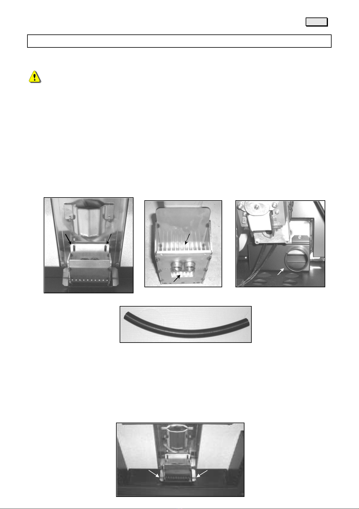
PELLETBURNER
For correct operation of the machine it is important that the crucible is maintained clean and free as possible
from each combustion residuecan therefore clean, therefore, at least once a week perform the following
cleaning:
Extract the crucible unhooking it from the two supports (fig. A) and remove all of the ash inside and at the
bottom into the slit (fig. B),making sure then to reposition it properly in its place.
Aspire the combustion air inlet (fig. C) using the supplied flexible hose (fig. F) to be connected to your vacuum
cleaner. The supplied perforated grille to be positioned within the crucible should only be used in case of high
chimney draft..
ASH TRAY
Every 24 hoursof operation, turn off the stove and proceed as described below:
- Open the doorof the furnace and remove the ash tray bylifting it by the handles (see figure).Emptyall the
ash, making sure that there are no embers.
- Aspire carefully all the ash on the bottom below the ash tray.
- Reinsert the trayin its place taking care to position it correctly.
Fig. C
Fig. F
Fig. A Fig. B Fig. C
ENGLISH
16
COMBUSTION SMOKE TUBING
At least once a weekproceed as described below:
-Remove the cap of smoke inspection, placed above the crucible, lifting it up and pulling it out (fig.A). Connect
vacuum cleaner to the hose supplied (picture C) and aspirate inside the cavities (fig.B) all of the combustion
residue, taking care to get up to flue gasfan through the opening on the right side.
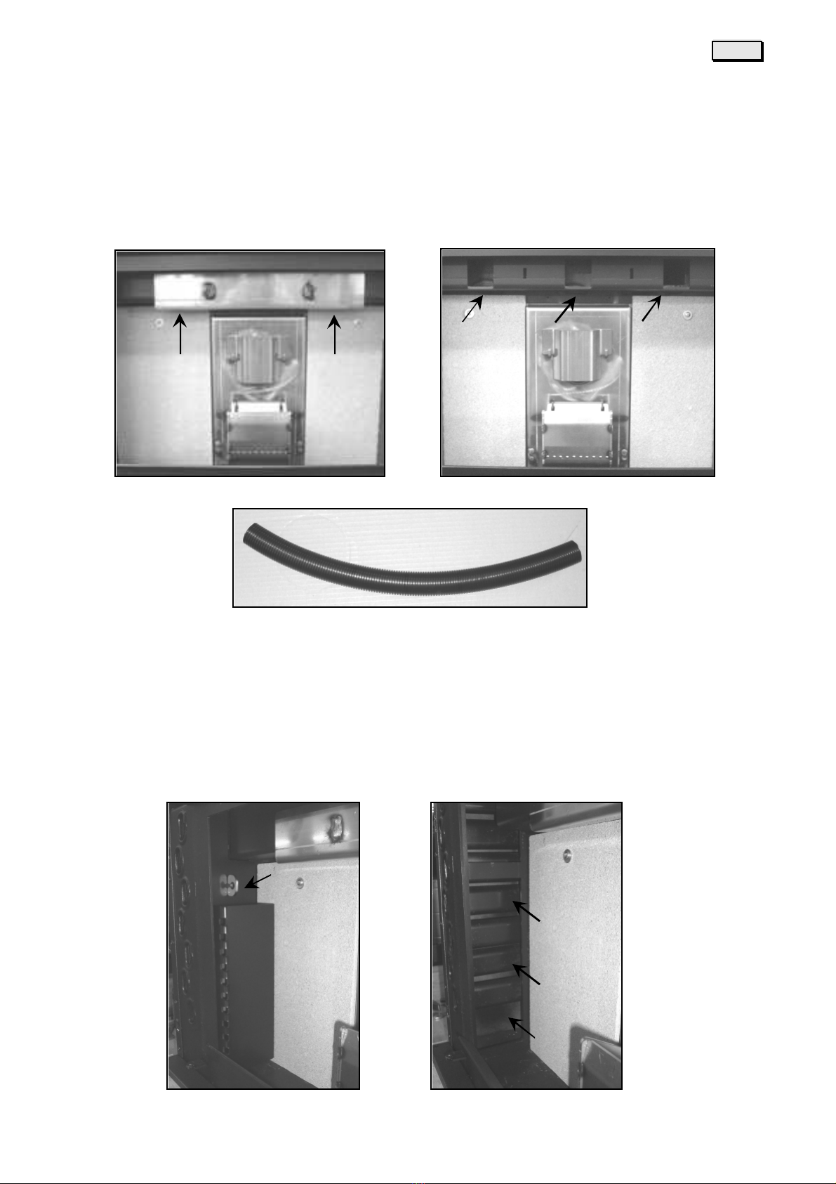
TUBE-BUNDLE HEATEXCHANGER
Inside the combustion chamber on both sides there are two removable bulkheads (Fig. A) for the internal
cleaning of the flue gas exchanger. At least once a week with the stove cold remove the sides bulkheads by
rotating the lockkey and pulling outward and aspirate all the combustion residue on the tube bundle and in the
niche at the base (fig.B). After cleaning make sure that you refit correctlyboth bulkheads.
Fig.C
Fig.A Fig.B
Fig.A Fig.B

ENGLISH
17
HEARTH GLASS DOOR
The glass used is resistant to high temperatures. Should it be damaged (e.g. chipped) it is recommended to
have it replaced immediately by an authorized technician before using the machine again. To clean, use a non
abrasive cloth with specificliquid forglass cleaning.
DO NOT attempt to repair damaged glass, replace it: asthere is a riskof explosion during functioning!
HEARTH DOOR SEAL
Frequently checkthe conditionsof the seal fixed along the internal border of the hearth door to ensure a tight
closure.
Note: check the tightness of the seal by inserting a piece of paper into the crack of the door whilst shut,
ensuring that this process is possible but proves difficult. If this is not the case contact an authorized after
sales service centre to have the seal replaced.
FLUE
Open, and if necessary cleaned, the "T" at the base of the flue duct and the horizontal section of pipe, if
present, at least once a weekto ensure a good operation.
The vertical duct of the flue gas and the entire flue must be checked and cleaned at least once a year.
We recommend that you contact a qualified technician for a thorough and professional cleaning.
GENERAL END OF SEASON CLEANING
After use, at the end of the season, clean and checkall the partsindicated above, remembering to disconnect
the power supplyof the stove for increased safety.
It is advisable to check and clean the machine at least once per year by an authorized technician to ensure
correct functioning.
For authorized technician: It is recommended, when required, to check lubrication of the pellet
auger bronze bearings.
ENGLISH
18
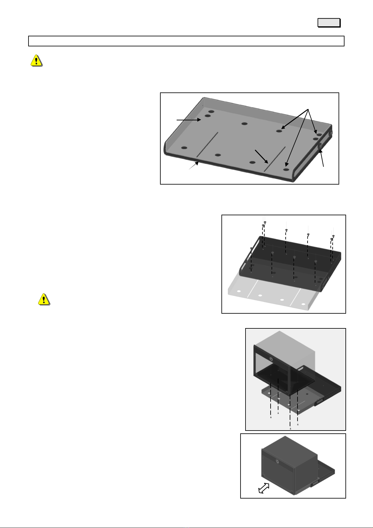
17. SLIDING GUIDES IT (OPTIONAL)
The manufacturer decline any responsibility for damages caused to people or things due to
improper use, installation or failure to follow the instructions below.
DESCRIPTION
A- BASE OF SUPPORT
B- SLED
C- BASE MOUNTING HOLES (N°10)
D- SLIDING SLOTS ASOLE
E- SLIDING BEARING
INSTALLATION
1- Place the base of support within the niche having a cement or
concrete bottom perfectly flat and drill all the holes provided
2- Now attach the base plate to the concrete bottom with
through screws (M8) or with iron plugs (not plastic) and
screws with not less than 8mm diameter, especially in the
backside (A) so that the base can not flex when you pull out
the sled.
Make sure that the bottom of the niche is perfectly
flat
3- Now pull out the sled afterleaning over the device, securely fasten the
slide bymeans of screws(B) through the sliding slots.
4- Checkthe correct assembly of the kit by doing some movementsof
extraction and insertion of the device.
A
B
E
D
C
A
A
B
B
ENGLISH
19
SERVICE
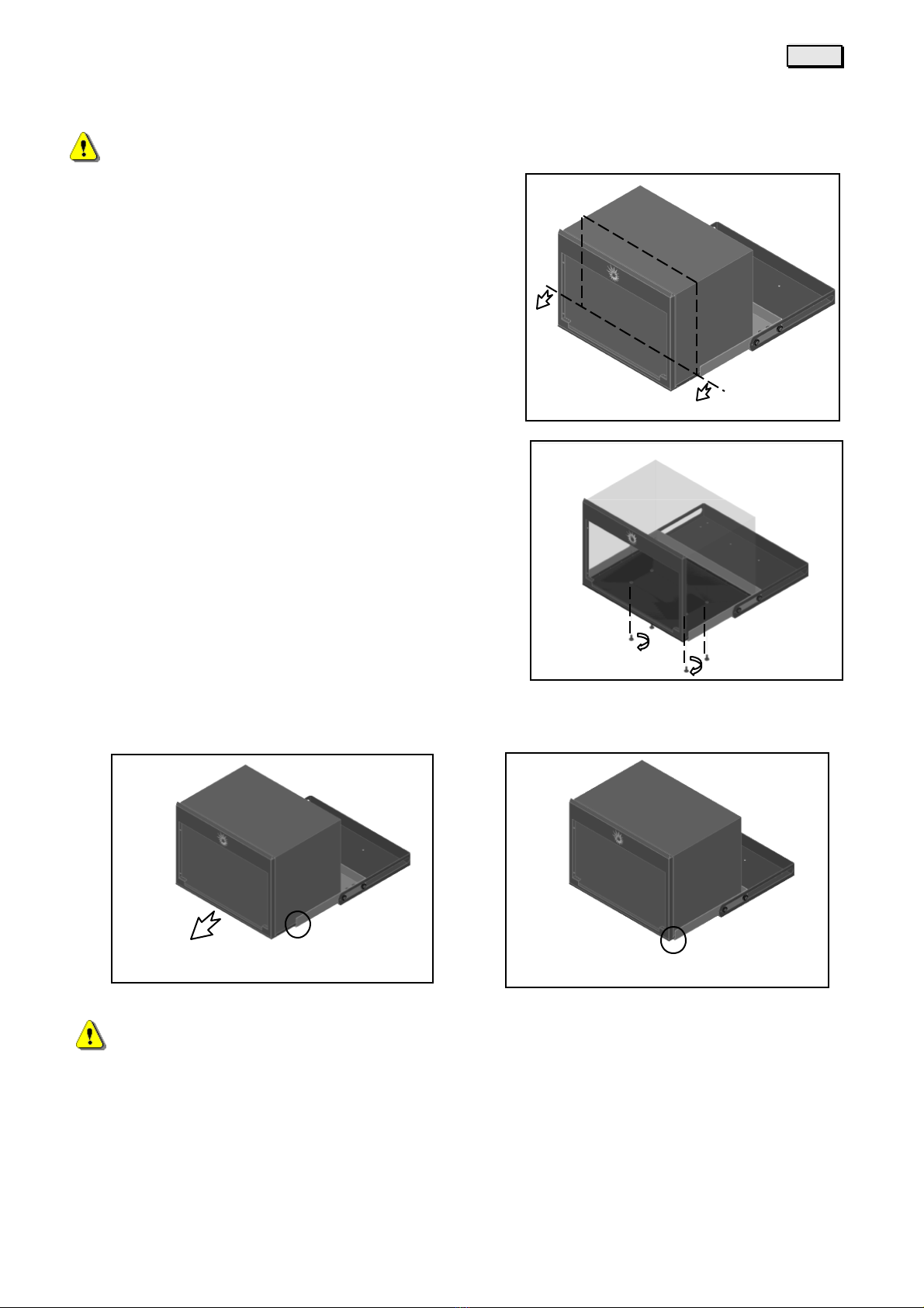
THE FOLLOWING OPERATIONS SOULD BE DONE BY AUTHORIZED SERVICE PERSONNEL ONLY
If necessary the total extraction of the device from the niche
(Fig. 1) to carry out the maintenance or monitoring operations,
proceed asdescribed below::
Pull out the sled and unscrew slightly (1/2 turn) the four
fastening screws (Figure 2) placed under the sled.
At thispoint lift slightly with both handsthe front of the device (fig.3) by sliding over the sled (fig.4).
Caution: danger of falling of appliance!! DO NOTremove completely the four screws.
Pay close attention.
1
3
4
2
Table of contents


