CS FA 510 User manual

FA510 V1.06
10
INSTRUCTION MANUAL
F
FA
A
5
51
10
0
The CS dew point sensor FA 510 with 3-wire technology 4…20 mA and RS
485 Modbus output enables a reliable and long-term stable monitoring of the dew
point in industrial applications such as in
- compressed air plants (refrigerating/adsorption dryers)
- granulate dryers
- medical gases
- non-corrosive gases, e. g. nitrogen

FA510 V1.06
11
FUNCTIONS
Page
Introduction / Intended use 11
Notes of safety 12
Description 12
Technical data 13
Diagram of instrument / Dimensions of instrument 14
Installation 15
Modbus Interface 16
Calibration/Adjustment 18
Warranty 18
Ordering details 18
Contact 20
INTRODUCTION
Dear Customer,
thank you for choosing the FA 510. Please read these installation and operating instructions
carefully before installation and commissioning and follow our instructions. The proper
functioning of the FA 510 and safe operation can only be ensured if the regulations and
instructions described are strictly observed.
Intended Use
The dew point sensor is intended for measuring the dew point or the pressure dew point in
clean, dry and oil-free gases and compressed air.
The user must check whether the instrument is suitable for the selected application. It must
be ensured that the medium is compatible with the wetted parts. The technical data listed in
the data sheet are obligatory.
Improper handling or operation outside the technical specifications is not permitted. Claims of
any kind based on improper use are excluded.

FA510 V1.06
12
NOTES ON SAFETY
Read these operating instructions carefully before installing the FA 510.
Failure to observe the instructions contained herein, in particular the
safety instructions, may result in hazards to personnel, equipment and
systems..
x The product may only be used in accordance with its intended purpose.
x Installation of the dew point sensor and maintenance work may only be carried
out by trained personnel.
x Installation and service work must be carried out in a de-energized state.
x The applicable safety regulations must be observed!
x All work on the compressed air network must only be carried out in a
depressurized state.
x Attention: Do not exceed the pressure range > 50 bar for the standard version.
x Observe the measuring ranges of the sensor!
Overheating will destroy the sensors.
x Observe the permissible storage and transport temperature as well as the
permissible operating temperature (e.g. protect the measuring instrument from
direct sunlight).
x Opening the instrument, improper handling or use of force will void all warranty
claims!
x Important: Before installation, briefly allow compressed air to flow off to remove
condensate and particles, this will prevent soiling of the FA 510.
x Standing air leads to long measuring times
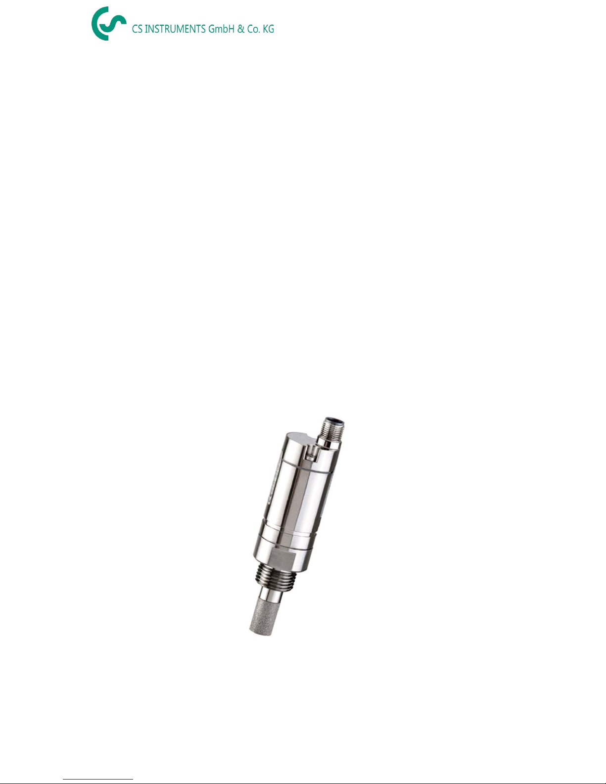
DESCRIPTION
The FA 510 dew point sensor enables a reliable and long-term stable monitoring of the dew
point in industrial applications. The FA 510 features improved stability.
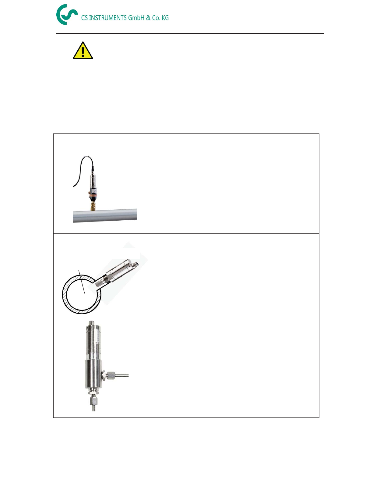
When mounting FA 510 into compressed air systems the pressure dew point (dew point
under pressure) up to 50 bar (in the special version up to 350 bar) is measured directly.
When mounting FA 510 in atmospheric conditions (ambient pressure) or in the flow off sector
(relaxed air) of compressed air systems the atmospheric dew point is measured.
Advantages:
x Dew point sensor for very low dew points down to -80 °Ctd
x Extremely long-term stable due to internal automatic calibration
x IP 65 housing grants a reliable protection in extreme industrial conditions
x Very fast response time
x Installable in the dryer by means of G 1/2" thread, optional UNF 5/8” or NPT ½”
x High accuracy of r 2 °Ctd
x Calibration on location and testing with CS control and calibration set (PC connection
set)
Programming via Software.
With the CS Service Software incl. USB / Modbus Adapter the Modbus settings, the scaling of the
Analogue output and the assignment of the measurement values could be set.
- Analogue output 4…20 mA scalable
- Switching between °Ctd,°Ftd, % RH, °C, °F, g/m³, mg/m³, g/kg, ppm, and so on
- Calibration and adjustment
- Sensor diagnosis
- Read-out of service data
!

FA510 V1.06
13
TECHNICAL DATA
Measuring range -80…50 °Ctd pressure dew point resp. dew point in °Ctd
0…100 % RH
-20…70 °C
Type 0699.0510, FA 510 -80…20 °Ctd ≙ 4…20 mA
Type 0699.0512, FA 510 -20…50 °Ctd ≙ 4…20 mA
Other scales on request, for example, -60 ... 30 ° Ctd ؙ 4 ... 20 mA
Accuracy: typical r 1 °Ctd von 20…-20 °Ctd
r 2 °Ctd von -50…-20 °Ctd
r 3 °Ctd von -50…-80 °Ctd
Pressure range: -1…50 bar standard
Power supply: 24V VDC (10..30 VDC)
Output: 4…20 mA 3-wire technology**
RS 485 (Modbus RTU) **
Protection class: IP 65
EMV: DIN EN 61326
Operating temperature: -20…70 °C (ideal 0…50 °C)
Storage temperature: -40…80 °C
Load for analogue output: < 500 Ohm
Screw-in thread: G 1/2" stainless steel
Optional: UNF 5/8” or NPT ½”
Material of housing: zinc alloy
Sensor protection: sinter filter 50 Pm stainless steel
Connection: M12, 5-pole
** Remark: Parallel use of analogue 4…20mA and RS 485 Modbus output is possible

FA510 V1.06
14
If no connection cable (0553.0104,
0553.0105) is ordered, the sensor
will be supplied with a M12
connect
or plug. The user can
connect the supply and signal
cables as indicated in the
connection diagram.
DIAGRAM OF INSTRUMENT
1
23
4
30,2
123,2
Dimensions
Pin 1
Pin 2
Pin 3
Pin 4
Pin 5
FA 510
Connector plug
+VB
RS485 A
-VB
RS485 B
+I
Current output
Connection cable
0554
.0104 (5 m)
0554.0105 (10 m)
brown
white
blue
black
grey
+VB
Positive supply voltage 24VDC (10...30 VDC) smoothed
RS485 A
Modbus A (+)
-VB
Negative supply voltage
RS485 B
Modbus B (-)
+I
Positive 4...20 mA signal **
** Measuring value assignment for 4-20mA signal selectable
Remark: The sensor must be connected in strain less state only
M12 connector plug Wiring diagram
Connector plug
M12 Connector plug

FA510 V1.06
15
INSTALLATION
x The direct installation of the sensor
is only allowed in the unpressurized state
of the system
x • The sensor must be tightened with a torque of 25 - 30 Nm.
x Tightness of the connection must be checked and ensured.
x
It is not permitted to use a sealing ring with a NPT 1/2“ thread. Appropriate
PTFE sealing tape or sealant should be used instead
Please note: CS recommends the indirect installation with measuring chamber
Advantage: Easy mounting and dismounting of the probe without interruption of the line.
Quick response time due to quick coupling. Optimum sensor protection.
Indirectly in the compressed air system
Connect probe wi
th measuring chamber to the
compressed air
pipe by means of a quick coupling.
In
case of compressed air containing oil and dirt particles
a pre
-
filter should be installed in front of the measuring
chamber
.
Compressed air flows continuously (at 7 bar
approx. 1 l/min expanded) in the capillary pipe of the
measuring chamber. The reaction times for the humidity
reading are shorter than in case of a direct mounting.
Directly in the compressed air system
Screw in probe with G 1/2" thread pressure
-tigh
t in the
center or at the top of the compressed air pipe. Take
care that measurement is effected close to the
compressed air flow. U
-bend pipes or non-flowing
compressed air
,
result in very slow reaction times for
the moisture reading
.
Measurable gases
In general, humidity can be measured in all non
-
corrosive gases.
In case of measurements in
corrosive gases please consult CS Instruments GmbH.
FA 510
FA 510
FA 510
compressed air pipe
Measuring chamber
Standard connection
compressed air pipe

FA510 V1.06
16
Modbus
The dew point sensor FA 510 comes with a Modbus RTU Interface.
Before commissioning of the sensor the communication parameters
Modbus ID, Baudrate, Parity und Stop bit
must be set in order to ensure the communication with the Modbus master.
The adjustment can be done either with the CS Instruments PC service software, DS 400, DS
500 and the hand-held instrument PI 500 done.
Modbus communication default values:
x Modbus ID : 1 (1 -247)
x Baudrate: 19200 bps (1200,2400, 4800, 9600, 19200, 38400 bps)
x Parity: even (none, even, odd)
x Stoppbit: 1 (1,2)
Supported are following functioncodes:
x Function code 03: Read Holding Register
x Function code 16: Write multiple Register
Register Mapping measuring values:
Modbus
Register
Modbus
Address
No.of
Byte
Data Type
Description
Defau
lt
Settin
g
Read
Write
Unit /Comment
1001
1000
4
Float
Temperature
R
[°C]
1003
1002
4
Float
Temperature
R
[°F]
1005
1004
4
Float
Relative Humidity
R
[%]
1007
1006
4
Float
Dew Point
R
[°Ctd]
1009
1008
4
Float
Dew Point
R
[°Ftd]
1011
1010
4
Float
Absolute Humidity
R
[g/m³]
1013
1012
4
Float
Absolute Humidity
R
[mg/m³]
1015
1014
4
Float
Humidity Grade
R
[g/kg]
1017
1016
4
Float
Vapor Ratio (Volume)
R
[ppm]
1019
1018
4
Float
Saturation vapor pressure
R
[hPa]
1021
1020
4
Float
Partial Vapor Pressure
R
[hPa]
1023
1022
4
Float
Atmospheric DewPoint
R
[°Ctd]
1025
1024
4
Float
Atmospheric DewPoint
R
[°Ftd]
Remark for DS400 / DS 500 / Handheld devices - Modbus Sensor Datatyp:
„Data Typ R4-32“ match with „Data Type Float“
Modbus

FA510 V1.06
17
Modbus Settings (2001…2006)
Modbus
Register
Mo
dbus
Address
No.of
Byte
Data Type
Description
Default
Setting
Read Write
Unit /Comment
2001
2000
2 UInt16
Modbus ID
1 R/W
Modbus ID 1…247
2002
2001
2 UInt16
Baudrate
4 R/W
0 = 1200
1 = 2400
2 = 4800
3 = 9600
4 = 19200
5 = 38400
2003
2002
2 UInt16
Parity
1 R/W
0 = none
1 = even
2 = odd
2004
2003
2 UInt16
Number of Stopbits
R/W
0 = 1 Stop Bit
1 = 2 Stop Bit
2005
2004
2 UInt16
Word Order
0xABCD
R/W
0xABCD = Big Endian
0xCDAB = Middle Endian
2006
2005
2 UInt16
Modbus Enabled
FA510: 1
FA515: 0
R/W
0 = Mod
bus disabled
1 = Modbus Enabled
Analog Scaling Settings (2007…2011)
Modbus
Register
Modbus
Address
No.of
Byte
Data Type
Description
Default
Setting
Read Write
Unit /Comment
2007
2006
4 UInt32
Output Value 4 R/W
0 = 4
-20mA disabled
1 = Temperature [°C]
2 = Temperature [°F]
3 = relative Humidity [%]
4 = DewPoint [°C]
5 = DewPoint [°F]
6 = Absolute Humidity [g/m3]
7 = Absolute Humidity [mg/m3]
8 = Humidity Grade [g/kg]
9 = Vapor Ratio [ppm]
10 = Saturation Vapor Pressur [hPa]
11 = Partial Vapor Pressure [hPa]
12 = Atmospheric DewPoint [°C]
13 = Atmospheric DewPoint [°F]
2009
2008
4
float
4mA Scale Low
-80
R/W
2011
2010
4
float
20mA Scale High
20
R/W
Modbus installation, Modbus settings and further information refer to the manual CS
Instruments "Modbus Installation and Operating Instructions FA 5xx sensors"

FA510 V1.06
18
CALIBRATION/ADJUSTMENT
From the manufacturer
According to DIN ISO certification of the measuring instruments we recommend regular
calibration and, if necessary, adjustment of the instrument by the manufacturer. The
calibration cycles should fit your internal scheme. In the course of the DIN ISO certification,
we recommend for FA 510 a calibration cycle of one year. If requested we can carry out the
calibration on your premises.
WARRANTY
If you have reason for complaint, we will of course repair any faults free of charge if it can be
proven that they are manufacturing faults. The fault should be reported immediately after it
has been found and within the warranty time guaranteed by us. Excluded from this warranty
is damage caused by improper use and non-adherence to the instruction manual.
The warranty is also cancelled once the measuring instrument has been opened provided
this is not described in the instruction manual for maintenance purposes. This is also the
case if the serial number has been changed, damaged or removed.
The warranty time for FA 510 is 12 months for the instrument and 6 months for accessories if
no other terms are agreed upon. Warranty services do not extend the warranty time.
If in addition to the warranty service necessary repairs, adjustments or similar are carried out,
the warranty services are free of charge but there is a charge for other services such as
transport and packing costs. Other claims, especially those for damage occurring outside the
instrument are not included unless responsibility is legally binding.
After-sales service after the warranty time has elapsed
We are, of course, there for you after the warranty time has elapsed. In the case of function
faults please send us your measuring instrument with a brief description of the defect. Please
also indicate your telephone number so that we can contact you if necessary.
ORDERING DETAILS
Order no.
Description
0699.0510
FA 510 dew point sensor (-80…20 °Ctd)
0699.0512
FA 510 dew point sensor (-20…50 °Ctd)
0553.0104
Connection cable, length: 5 m
0553.0105
Connection cable, length:10 m
0699.3390
Standard measuring chamber for compressed air up to 16 bar
0699.3590
High-pressure measuring chamber up to 350 bar *
0699.3690
Measuring chamber for atmospheric dew point
0699.3790
Measuring chamber for respiratory air bottles up to 350 bar *
0699.4004
Special scaling, output in g/kg, % RH, mg/m³, ppm (V/V), g/m³
0699.3396
Precision calibration at -40 °Ctd or 3° Ctd incl. ISO certificate
3200.0003
Precision calibration at 0 °Ctd and 10 °Ctd incl. ISO certificate
CS Service Software for FA/VA sensors incl. PC connection set,
USB connection and interface adapter to the sensor

FA510 V1.06
19
KONFORMITÄTSERKLÄRUNG
DECLARATION OF CONFORMITY
Wir CS Instruments GmbH & Co.KG
We Am Oxer 28c, 24955 Harrislee
Erklären in alleiniger Verantwortung, dass das Produkt
Declare under our sole responsibility that the product
Feuchtesensoren FA 510 / FA 515
Dew point sensors FA 510 / FA 515
den Anforderungen folgender Richtlinien entsprechen:
We hereby declare that above mentioned components comply with requirements of the following EU directives:
Elektromagnetische Verträglichkeit
Electromagntic compatibility
2014/30/EUG
2014/30/EC
RoHS
(Restriction of certain Hazardous Substances)
2011/65/EC
Angewandte harmonisierte Normen:
Harmonised standards applied:
EMV-Anforderungen
EMC requirements
EN 55011: 2011-04
EN 61326-1: 2013-07
Anbringungssjahr der CE Kennzeichnung: 15
Year of first marking with CE Label: 15
Das Produkt ist mit dem abgebildeten Zeichen gekennzeichnet.
The product is labelled with the indicated mark.
Harrislee, den 19.04.2016

FA510 V1.06
20
Kontakt / CONTACT
CS INSTRUMENTS GmbH & Co.KG
Geschäftsstelle Süd / Sales Office South /
Zindelsteiner Str. 15
D-78052 VS-Tannheim
Tel.: +49 (0) 7705 978 99 0
Fax: +49 (0) 7705 978 99 20
Mail: [email protected]om
Web: http://www.cs-instruments.com
Geschäftsstelle Nord / Sales Office North
Am Oxer 28c
D-24955 Harrislee
Tel.: +49 (0) 461 700 20 25
Fax: +49 (0) 461 700 20 26
Mail: [email protected]
Web: http://www.cs-instruments.com
Table of contents
Other CS Accessories manuals
Popular Accessories manuals by other brands

Aqara
Aqara Temperature and Humidity Sensor quick start guide

FIBARO
FIBARO FGBHFS-101 operating manual

Bircher Reglomat
Bircher Reglomat MIS quick start guide

WallSenzr
WallSenzr BDS-700 Series installation instructions

Panasonic
Panasonic GA-311 instruction manual

AIA
AIA SEE COOLING SEE Cooler Series user guide