CST/BERGER Magna-Trak 100 C19550 User manual
1
INSTRUCTION MANUAL
Magna-Trak 100®
Magnetic Locator

2
Thank you for purchasing the Magna-Trak 100®Magnetic Locator. Please read this manual thoroughly before
operation.
CONTENTS
1. Introduction ............................................................................................................................ 3
2. Theory of Operation................................................................................................................. 3
3. Features .................................................................................................................................. 4
4. Basic Operation and Description.............................................................................................5
4.1 Power ON/OFF Switches ........................................................................................................................ 5
4.2 Volume and Sensitivity Control Knobs...................................................................................................... 5
4.3 Speaker ................................................................................................................................................ 5
4.4 LCD Visual Display................................................................................................................................. 5
5. Battery Replacement............................................................................................................... 6
6. Field Operation........................................................................................................................ 7
6.1 Water Locations .................................................................................................................................... 8
6.2 Locating Near a Steel Fence................................................................................................................... 8
7. Signal Response...................................................................................................................... 9
7.1 Typical Signal Responses ..................................................................................................................... 10
8. Specifications .......................................................................................................................11
9. Warranty & Service ............................................................................................................... 11
3
1. INTRODUCTION
The Magna-Trak 100®magnetic locator is a flux-gate type of magnetometer which incorporates a unique patented
technology that enables the factory to balance the magnetic sensing coils to a finite condition. This patented
method of magnetic balancing is advanced in the state of the technology.
The Magna-Trak 100 implements “peak response” over ferromagnetic objects by yielding an increasing audio
signal as the object is approached and passed over.
This instrument is the product of many years of experience and service provided by CST to the industry.
2. THEORY OF OPERATION
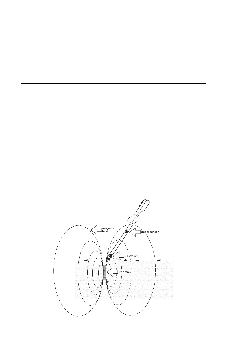
The Magna-Trak 100 locator finds ferromagnetic objects by sensing the magnetic field radiated by the object.
The locator contains two sensor coil assemblies that are precisely spaced and electronically balanced to achieve
a near magnetically-balanced operating condition. In a uniform magnetic field, such as the earth’s field, the two
sensor coils maintain a magnetically-balanced status, because both of the coils experience the same magnetic
lines of force. However, when a ferromagnetic object is approached, the field strength and angle of the magnetic
lines upon each sensor is different. This difference, although minute, is enough to offset the critical balance and
produce an audible indicating signal (Fig. 1).
When no ferromagnetic objects are present, the speaker emits a steady low frequency tone. As the object is
approached, the audio frequency increases until the center of the object is directly beneath the locator’s lower tip
sensor. The frequency peaks and then decreases as the object is passed. The peak indicates the exact location of
the object.
Nonferrous objects do not affect the locator. Objects made of brass, aluminum, copper, etc. are ignored.
Fig. 1
Sensor coils unbalanced by magnetic field of iron stake.
4
3. FEATURES
• Rugged high-impact plastic enclosure with aluminum sensor pole
• Powerful magnetic speaker with waterproof Mylar cone
• Lightweight, comfortably balanced for easy handling
• Easy view LCD display for visual signal strength and battery information:
includes two digit numeric signal indicator, expanding analog Bar-Graph signal indicator,
and flashing “Low Battery” indicator
• Six “AA” (11⁄2volt) battery operation; Approximately 25 hours battery life
• Quick-access battery compartment
• Adjustable sensitivity and volume controls
• Single hand touch-switch operation for power ON/OFF
• Deep tone audio under search conditions; signals “peak” over magnetic objects
• Full depth capability
• Includes padded carrying case with shoulder strap or hard case

5
4. BASIC OPERATION AND DESCRIPTION
4.1 Power On/Off Switches
Press “ON” once to activate the locator circuitry. Press “OFF” once to turn the battery power off.
4.2 Volume and Sensitivity Control Knobs
Rotate the volume knob to the desired audio volume level. Full volume is achieved when the knob is turned fully
clockwise.
The sensitivity or depth range can be varied using the sensitivity knob. Maximum range is provided at full
clockwise rotation. The optimal setting is determined by each particular application. Areas crowded with various
undesired ferrous objects may require a reduced sensitivity level. Deeply buried objects being searched will require
a higher sensitivity level.
A decal with markings for both the sensitivity and volume control knobs is provided as a reference for future
settings or comparisons.
4.3 Speaker
When no ferrous metal is present, the audio sound heard will be a low frequency tone. As ferrous metals are
approached, the audio tone will increase.
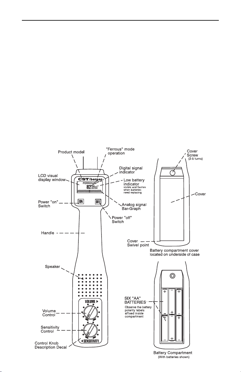
4.4 LCD Visual Display
Several visual display functions, provided for ease of operation, are defined below:
“Ferrous”
Defines the basic function of the locator as a ferrous locator (fixed indicator).
Digital Signal Indicator
A two digit numeric display shows the signal level as related to the audio signal response being heard from the
speaker. At the lowest signal level, when no ferrous metal is present, a small number will be viewed (between “0”
and “5”). As metal is approached, the numbers will increase, reaching “99” at its maximum peak. Deeply buried
objects or lower sensitivity levels will yield a lower peak number to aid in pinpointing the object.
Analog Bar-Graph Signal Indicator
The bar graph display expands outward from the center “diamond” as related to the audio signal response being
heard from the speaker.
Table of contents


