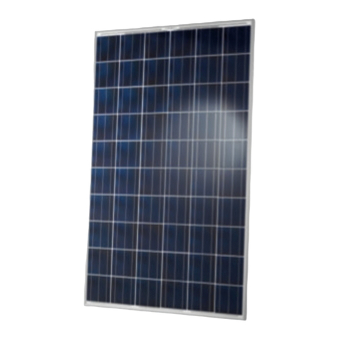
CSUN 305-72M User manual

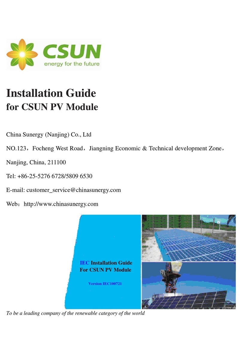
IEC Installation Guide
Web:
Q/CSUN.J30.0002
To be a leading company of the renewable category of the world

Contents
1、
、、
、General Information
2、
、、
、Safety Pre aution
⑴Storage and unpacking
⑵Installation Announcements
3、
、、
、
4、
、、
、
⑴
⑵
⑶
⑷
⑸
5、
、、
、
6、
、、
、

1、
、、
、General Information
This guide contains information regarding the installation and safe handling of the photovoltaic module
(hereafter is referred to as “module”) produced by hina Sunergy (Nanjing) o., Ltd (hereafter is referred to
as “ SUN”.)
Installers must read and understand the guide before installation. Any questions, please contact our
customer service department for further explanations. The installer should conform to all safety precautions in
the guide and local codes when installing a module. Failure to follow these instructions may result in death,
bodily injury or damage to property.
Before installing a solar photovoltaic system, installers should become familiar with the mechanical and
2、
、、
、
⑴
⑴⑴
⑴
◆
◆
◆
◆
◆
◆
◆
⑵
⑵⑵
⑵
◆ When installing the system, abide with all local, regional and national statutory regulations. Obtain a
building permit where necessary.
◆ Installing solar photovoltaic systems may require specialized skills and knowledge. Installation should be
performed only by qualified persons. Installers should assume the risk of all injury that might occur during
installation, including, without limitation, the risk of electric shock.
◆ Abide with the safety regulations for all other components used in the system, including wiring and cables,
connectors, charging regulators, inverters, storage batteries and rechargeable batteries, etc. Use only

equipment, connectors, wiring and support frames suitable for a solar electric system. Always use the
same type of module within a particular photovoltaic system.
◆ Photovoltaic modules are designed for outdoor use. Modules may be mounted on ground, rooftops,
vehicles or boats. Proper design of support structures is responsibility of the system designers and
installers. Use of mounting holes is suggested in a following paragraph.
◆ Do not install or handle the modules when they are wet or during periods of high wind. Keep the junction
box cover closed at all times.
◆ Do not use or install broken modules. If the glass is broken, or the back sheet is torn, contact with any
modules surface or the frame can cause electric shock.
◆
◆
◆
◆
current.
◆
◆
◆ Under normal outdoor conditions the module will produce current and voltages that are different than
those listed in the date sheet. Data sheet values are values expected at standard test conditions.
Accordingly, during system design, values of short-circuit current and open-circuit voltage should be
multiplied by a factor of 1.25 when determining component voltage ratings, conductor ampacity, fuse
ratings and size of controls connected to the modules or system output.
3、
、、
、Produ t Identifi ation
Each module has five labels providing the following information:

◆ Nameplate:describes the product type, rated power, rated current, rated voltage, open circuit voltage,
short circuit current, all are measured at ST ; weight, dimension, maximum system voltage, the fuse
rating and power tolerance are all shown on the nameplate. Generally,power tolerance is ±3%。
◆ Barcode:each module has a unique serial number. The serial number has 16 digits. The “ SUN” is the
short name for hina Sunergy (Nanjing) o., Ltd. The 5th digit refers to the cell manufacturer, AB used
to represent. And the 6th digit refers to the modules manufacturer address, AB used to represent. The 7th
digit refers to the modules production month. AB used to represent. For example, “A” refers to
“January”; “L” refers to “December”;The 8th digit refers to the modules production workshop. “1”
◆
◆
4、
、、
、
⑴
⑴⑴
⑴
◆
◆ For detailed information on the best elevation tilt angle for the installation, refer to standard solar
photovoltaic installation guides or a reputable solar installer or systems integrator.
⑵
⑵⑵
⑵ Sele ting the proper support frame
◆ Always observe the instructions and safety precautions included with the support frames to be used with
the modules. Do not attempt to drill holes in the glass surface or additional mounting holes in the frame.
To do so will void the warranty.

◆
◆
material.
◆
⑶
⑶⑶
⑶
◆
◆ When installing module on a roof, ensure that the roof construction is suitable. In addition, any roof
penetration required to mounting the module must be properly sealed to prevent leaks. In some cases, a
special support frame may be necessary.
◆ The roof installation of solar modules may affect the fireproofing of the house construction. The modules
Fire Resistance rated lass is lass , and are suitable for mounting over a class A roof. Do not install
modules on a roof or building during strong winds in case of accidents.

⑷
⑷⑷
⑷ Pole mounting
◆ When installing a module on a pole, choose a pole and module mounting structure that will withstand
anticipated winds and snow for the area.
⑸
⑸⑸
⑸
◆
◆
◆
◆
◆
⑹
⑹⑹
⑹ Grounding
◆
conductor or strap may be copper, copper alloy, or other material acceptable for use as an electrical
conductor per respective National Electrical odes. The grounding conductor must then make a
connection to earth using a suitable earth ground electrode.
◆ Attach a separate conductor as grounding wire to one of the 6mm diameter grounding holes marked with
the grounding symbol on the module frame with a set of M4 or M5 screw, cup washer, flat washer, tooth
washer, and M4 or M5 nut. This is to ensure positive electrical contact with the frame.

5、
、、
、
◆
◆
◆
◆
◆
6、
、、
、
◆
◆

Appendix 1:
::
:CSUN Main Modules Te hni al spe ifi ations
Model Type S ope Cell Number Cell Size (mm) Module Size(
((
(mm)
))
)

Spe ifi ations of CSUN 295-72M Mono rystalline solar module
Type CSUN
305-72M
CSUN
300-72M
CSUN
295-72M
CSUN
290-72M
CSUN
285-72M
Ele tri al typi al data
Pmpp [W] 305 300 295 290 285
Voc [V] 44.9 44.8 44.6 44.5 44.4
Isc [A] 8.87 8.80 8.73 8.67 8.60
Maximum surface load capacity 5,400 Pa
Hail maximum diameter of 25 mm with impact speed of 23 m·s-1
Temperature range – 40 ° to + 85 °

Dimensions
Note:
The ele tri al data relates to standard test onditions [STC]: 1,000 W/m²; AM 1,5; 25°C.
Performan e deviation of Pmpp: -/+ 3%.
Performan e deviation of Vo [V],Is [A],Vmpp [V] and Impp [A]: -/+ 10%.
Certified in a ordan e with IEC 61215, IEC 61730-1/2 and UL 1703.
0
2
4
6
8
10
1000W/m2
800W/m2
600W/m2
400W/m2
200W/m2
0
50
100
150
200
250
300
350
2

Spe ifi ations of CSUN 290-72P Poly rystalline solar module
Type CSUN
290-72P
CSUN
285-72P
CSUN
280-72P
CSUN
275-72P
CSUN
270-72P
CSUN
265-72P
Ele tri al typi al data
Pmpp [W] 290 285 280 275 270 265
Dimensions 1956×990×50mm (L×W×H)
Maximum surface load capacity 5,400 Pa
Hail maximum diameter of 25 mm with impact speed of 23 m·s-1
Temperature range – 40 ° to + 85 °

Dimensions
Note:
The ele tri al data relates to standard test onditions [STC]: 1,000 W/m²; AM 1,5; 25°C.
Performan e deviation of Pmpp: -/+ 3%.
Performan e deviation of Vo [V],Is [A],Vmpp [V] and Impp [A]: -/+ 10%.
Certified in a ordan e with IEC 61215, IEC 61730-1/2 and UL 1703.
0
2
4
6
8
10
1000W/m2
800W/m2
600W/m2
400W/m2
200W/m2
0
50
100
150
200
250
300
350
2

Spe ifi ations of CSUN 245-60M Mono rystalline solar module
Type CSUN
255-60M
CSUN
250-60M
CSUN
245-60M
CSUN
240-60M
CSUN
235-60M
Ele tri al typi al data
Pmpp [W] 255 250 245 240 235
Voc [V] 37.5 37.3 37.2 37.0 36.8
Dimensions 1640×990×50mm (L×W×H)
Maximum surface load capacity 5,400 Pa
Hail maximum diameter of 25 mm with impact speed of 23 m·s-1
Temperature range – 40 ° to + 85 °

Dimensions
Note:
The ele tri al data relates to standard test onditions [STC]: 1,000 W/m²; AM 1,5; 25°C.
Performan e deviation of Pmpp: -/+ 3%.
Performan e deviation of Vo [V],Is [A],Vmpp [V] and Impp [A]: -/+ 10%.
Certified in a ordan e with IEC 61215, IEC 61730-1/2 and UL 1703.
0
2
4
6
8
10
1000W/m2
800W/m2
600W/m2
400W/m2
200W/m2
0
50
100
150
200
250
300
2

Spe ifi ations of CSUN 240-60P Poly rystalline solar module
Type CSUN 245-60P CSUN 240-60P CSUN 235-60P CSUN 230-60P CSUN 225-60P CSUN 220-60P
Ele tri al typi al data
Pmpp [W] 245 240 235 230 225 220
Voc [V] 37.1 36.9 36.8 36.7 36.6 36.4
Dimensions 1640×990×50mm (L×W×H)
Maximum surface load capacity 5,400 Pa
Hail maximum diameter of 25 mm with impact speed of 23 m·s-1
Temperature range – 40 ° to + 85 °

Dimensions
Note:
The ele tri al data relates to standard test onditions [STC]: 1,000 W/m²; AM 1,5; 25°C.
Performan e deviation of Pmpp: -/+ 3%.
Performan e deviation of Vo [V],Is [A],Vmpp [V] and Impp [A]: -/+ 10%.
Certified in a ordan e with IEC 61215, IEC 61730-1/2 and UL 1703.
0
2
4
6
8
200W/m2
400W/m2
600W/m2
800W/m2
1000W/m2
0
50
100
150
200
250
2

Spe ifi ations of CSUN 195-72M Mono rystalline solar module
Type CSUN
200-72M
CSUN
195-72M
CSUN
190-72M
CSUN
185-72M
CSUN
180-72M
Ele tri al typi al data
Pmpp [W] 200 195 190 185 180
Voc [V] 45.3 45.1 45.0 44.8 44.6
Dimensions 1580×808×35mm (L×W×H)
Maximum surface load capacity 5400 Pa
Hail maximum diameter of 25 mm with impact speed of 23 m·s-1
Temperature range – 40 ° to + 85 °

Dimensions
Note:mm(inch)
× ×
× ×
10.8(0.43)
Note:
The ele tri al data relates to standard test onditions [STC]: 1,000 W/m²; AM 1,5; 25°C.
Performan e deviation of Pmpp: -/+ 3%.
Performan e deviation of Vo [V],Is [A],Vmpp [V] and Impp [A]: -/+ 10%.
Certified in a ordan e with IEC 61215, IEC 61730-1/2 and UL 1703.
0
1
2
3
4
5
6
1000W/m2
800W/m2
600W/m2
400W/m2
200W/m2
0
50
100
150
200
2
This manual suits for next models
26
Other CSUN Solar Panel manuals
Popular Solar Panel manuals by other brands
Harbor Freight Tools
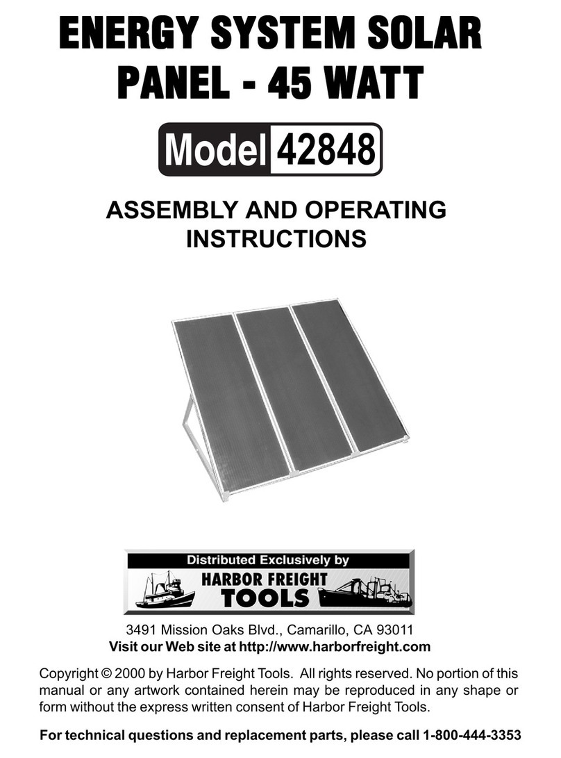
Harbor Freight Tools 42848 Assembly and operating instructions
CanadianSolar
CanadianSolar CS3U-MS-FG installation manual

Glowworm
Glowworm Clearly Solar installation instructions
Qcells
Qcells Q.PEAK DUO XL-G11.2 Series Installation and operation manual
evergreensolar
evergreensolar ES-A Series Mounting guide
Jinko Solar
Jinko Solar MM365-60HLM-MBV (BFR) installation manual
