CTC Union V Series User manual

“V” Series MIL-Style Boot Connector Kits“V” Series MIL-Style Boot Connector Kits
Product ManualProduct Manual

2
• Introduction...................................................................3
• Assembly for V2X Series ......................................................6
• Assembly for V3X Series ......................................................9
• Assembly for V4X Series .................................................... 12
• Maintenance ................................................................ 15
• Warranty & Return Information .............................................. 15
Table of Contents

3
Introduction
This document contains information on the operation, installation and
maintenance of the V-style series of connector kits.
Figure 2. 3-Socket Connector Kit Materials
Figure 1. 2-Socket Connector Kit Materials
Two-Conductor Cable
Insert
Backshell
VITON® Boot
Contacts x2
Ground
(-) Common
(+) Signal
Three-Conductor Cable
Insert
Backshell
VITON® Boot
Contacts x3
Ground
(-) Common
(+) Vibration Signal
(+) Temperature Signal

4
Figure 2. 4-Socket Connector Kit Materials
Four-Conductor Cable
Insert
Contacts x4
Backshell
VITON® Boot
(+) Axis X
Ground
(-) Common
(+) Axis Y
(+) Axis Z

5
Part # Connector Kit Parts Material
(Insert)
Max
Temp.
Connector Kit
Parts #
Compatible
Cables
V2J
CK-V2J
Polycarbonate,
VITON® Boot
250 °F
(121 °C)
CK-V2J CB111
V2R
CK-V2R
Polyphenylene
Sulfide,
VITON® Boot
350 °F
(177 °C)
CK-V2R CB111
V3R
CK-V3R
Polyphenylene
Sulfide,
VITON® Boot
350 °F
(177 °C)
CK-V3R CB112
V4J
CK-V4J
Polycarbonate,
VITON® Boot
250 °F
(121 °C)
CK-V4J CB119
Table 1. Product Selection Guide
Recommended Tool: CB926-1A Recommended Epoxy: MH109-3D

6
Assembly for Ck-V2x Series
1. Strip outer jacket of wire .300 in.
2. Cut off shield and drain wire (for twisted shielded wires only).
3. Strip the insulation of two conductor wires back .200 in.
4. Crimp conductor wires into contact sockets. CTC’s CB926-1A crimp tool
makes crimping fast and easy and can lead to significant time savings when
installing a large volume of connector kits. Adjusting the green depth knob
to the desired length allows the depth of the contacts to be set manually to
ensure a crimp at the correct location every time. Suggested depth for the
V2J is 0.43 in. Suggested depth for the V2R is 0.52 in.
5. Slide VITON® boot and backshell onto the cable.
0.300 in.
0.200 in.

7
6. Using a fine-tipped punch, gently press each contact into the appropriate
position on the insert.
a. Install accelerometer red (+) wire into the insert socket for Pin A.
b. Install accelerometer black (-) wire into insert socket for Pin B.
7. Thread the backshell onto the insert.
8. Place the assembled connector body horizontally with the two small epoxy
injection holes level and facing upward.
9. Mix epoxy. Using a syringe, fill the backshell with epoxy through one of the
small injection holes until epoxy begins to seep from the other.
10. Keep the connector in a horizontal position, allowing the epoxy to set and
vent any trapped air, refilling as needed.

8
11. Allow the epoxy to cure for six hours at room temperature. Place a piece of
masking tape over the two epoxy holes to prevent leakage and hang the
connector vertically with the insert facing downward. This will ensure epoxy
encapsulates the cable evenly, especially if the cable diameter is smaller
than the backshell opening.
12. Push the VITON® boot shell over the assembled connector body until it
snaps into place.
The connector body should be recessed approximately 0.125 in. from the tip of
the VITON® boot when properly installed.

9
Assembly for Ck-V3x Series
1. Strip outer jacket of wire .300 in.
2. Cut off shield and drain wire (for twisted shielded wires only).
3. Strip the insulation of three conductor wires back .200 in.
4. Crimp conductor wires into contact sockets. CTC’s CB926-1A crimp tool
makes crimping fast and easy and can lead to significant time savings when
installing a large volume of connector kits. Adjusting the green depth knob
to the desired length allows the depth of the contacts to be set manually to
ensure a crimp at the correct location every time. Suggested depth for the
V3R is 0.52 in.
5. Slide VITON® boot and backshell onto the cable.
0.300 in.
0.200 in.

10
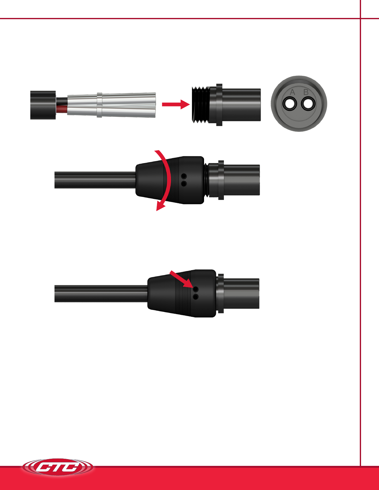
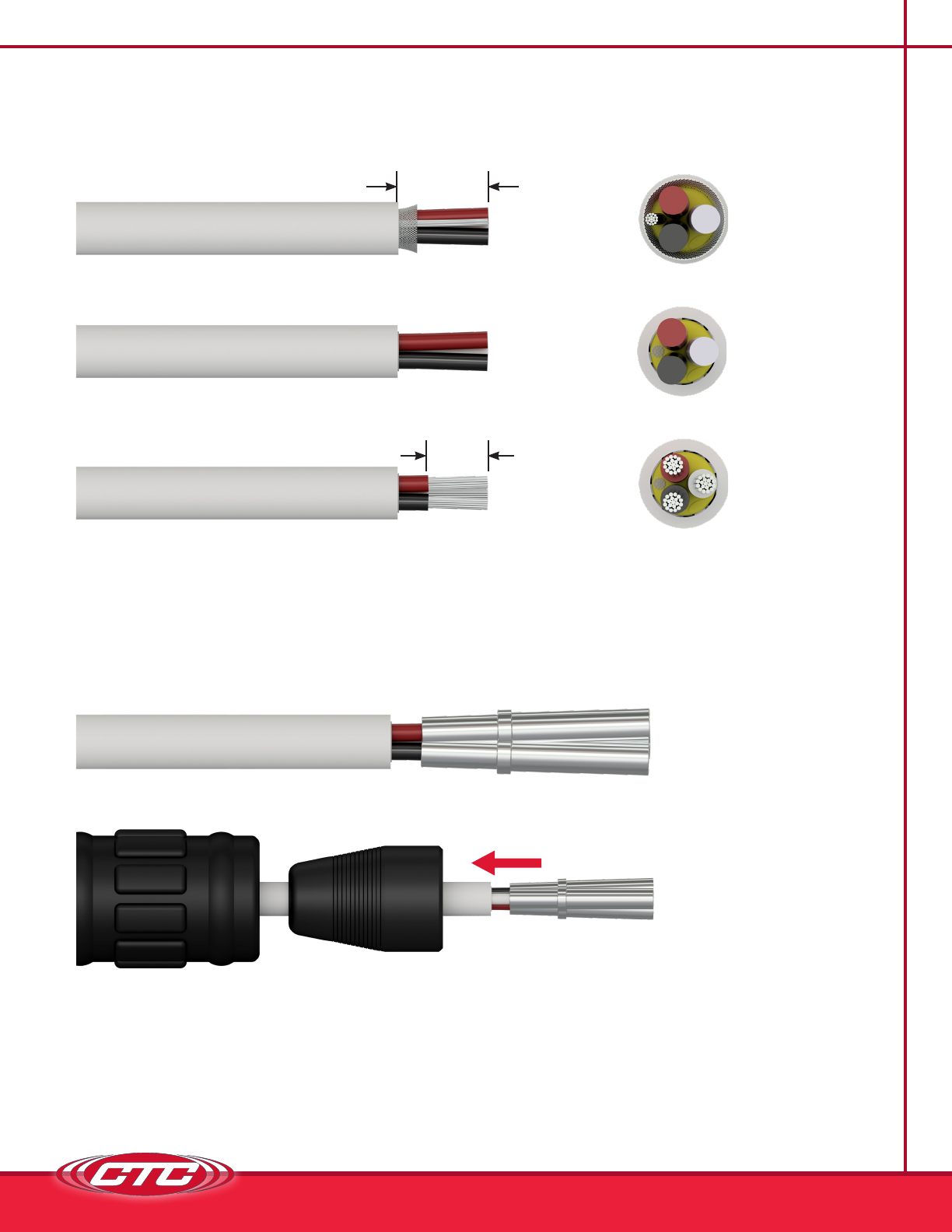
6. Attach O-ring to the front of the insert.
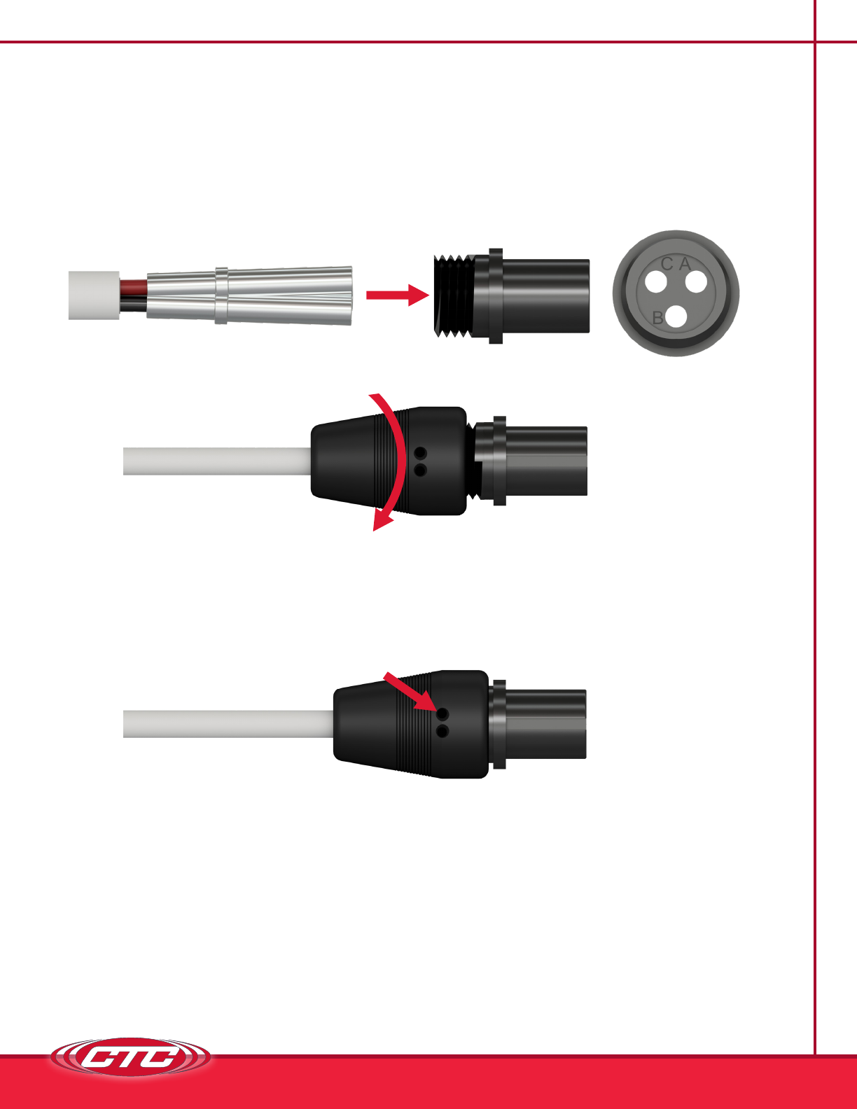
7. Using a fine-tipped punch, gently press each contact into the appropriate
position on the insert.
a. Install accelerometer red (+) wire into the insert socket for Pin A.
b. Install accelerometer black (-) wire into insert socket for Pin B.
c. Install accelerometer white (+) wire into the insert socket for Pin C.
8. Thread the backshell onto the insert.
9. Place the assembled connector body horizontally with the two small epoxy
injection holes level and facing upward.
10. Mix epoxy. Using a syringe, fill the backshell with epoxy through one of the
small injection holes until epoxy begins to seep from the other.
11. Keep the connector in a horizontal position, allowing the epoxy to set and
vent any trapped air, refilling as needed.

11
12. Allow the epoxy to cure for six hours at room temperature. Place a piece of
masking tape over the two epoxy holes to prevent leakage and hang the
connector vertically with the insert facing downward. This will ensure epoxy
encapsulates the cable evenly, especially if the cable diameter is smaller
than the backshell opening.
13. Push the VITON® boot shell over the assembled connector body until it
snaps into place.
The connector body should be recessed approximately 0.125 in. from the tip of
the VITON® boot when properly installed.

12
Assembly for Ck-V4x Series
1. Strip outer jacket of wire .300 in.
2. Cut off shield and drain wire (for twisted shielded wires only).
3. Strip the insulation of two conductor wires back .200 in.
4. Crimp conductor wires into contact sockets. CTC’s CB926-1A crimp tool
makes crimping fast and easy and can lead to significant time savings when
installing a large volume of connector kits. Adjusting the green depth knob
to the desired length allows the depth of the contacts to be set manually to
ensure a crimp at the correct location every time. Suggested depth for the
V4J is 0.43 in.
5. Slide VITON® boot and backshell onto the cable.
0.300 in.
0.200 in.

13
6. Using a fine-tipped punch, gently press each contact into the appropriate
position on the insert.
a. Install accelerometer red (+) wire into the insert socket for Pin A.
b. Install accelerometer green (+) wire into the insert socket for Pin B.
c. Install accelerometer white (+) wire into the insert socket for Pin C.
d. Install accelerometer black (-) wire into insert socket for Pin D.
7. Thread the backshell onto the insert.
8. Place the assembled connector body horizontally with the two small epoxy
injection holes level and facing upward.
9. Mix epoxy. Using a syringe, fill the backshell with epoxy through one of the
small injection holes until epoxy begins to seep from the other.

14
10. Keep the connector in a horizontal position, allowing the epoxy to set and
vent any trapped air, refilling as needed.
11. Allow the epoxy to cure for six hours at room temperature. Place a piece of
masking tape over the two epoxy holes to prevent leakage and hang the
connector vertically with the insert facing downward. This will ensure epoxy
encapsulates the cable evenly, especially if the cable diameter is smaller
than the backshell opening.
12. Push the VITON® boot shell over the assembled connector body until it
snaps into place.
The connector body should be recessed approximately 0.125 in. from the tip of
the VITON® boot when properly installed.

15
Maintenance
Once the product has been installed, minimal maintenance will be required. Basic
visual checks to ensure integrity should be made periodically.
General
There are no customer-replaceable parts. The product has been designed for
trouble-free service under normal operating conditions.
Mm-Ck-V2j/Rev A
Warranty & Refund
Warranty
All CTC products are backed by our unconditional lifetime warranty. If any CTC
product should ever fail, we will repair or replace it at no charge.
Refund
All stock products can be returned for a 25% restocking fee if returned in new
condition within 90 days of shipment. Stock products qualify for free cancellation
if your order is cancelled within 24 hours of purchase. Build to order products
qualify for a 50% refund if returned in new condition within 90 days of shipment.
Custom products are quoted and built specifically to the requirements of the
customer, which may include completely custom product designs or private
labeled versions of standard products for OEM customers. Custom products
ordered are non-cancellable, non-returnable and non-refundable.
This manual suits for next models
3
Table of contents
Other CTC Union Cables And Connectors manuals