~
j
i
SECTION
1 TABLE OF CONTENTS
DESCRIPTION
•••••••••••••••••..••••••••...••••••.•..•••••••.•••.•••....••••••••••.••••..
1
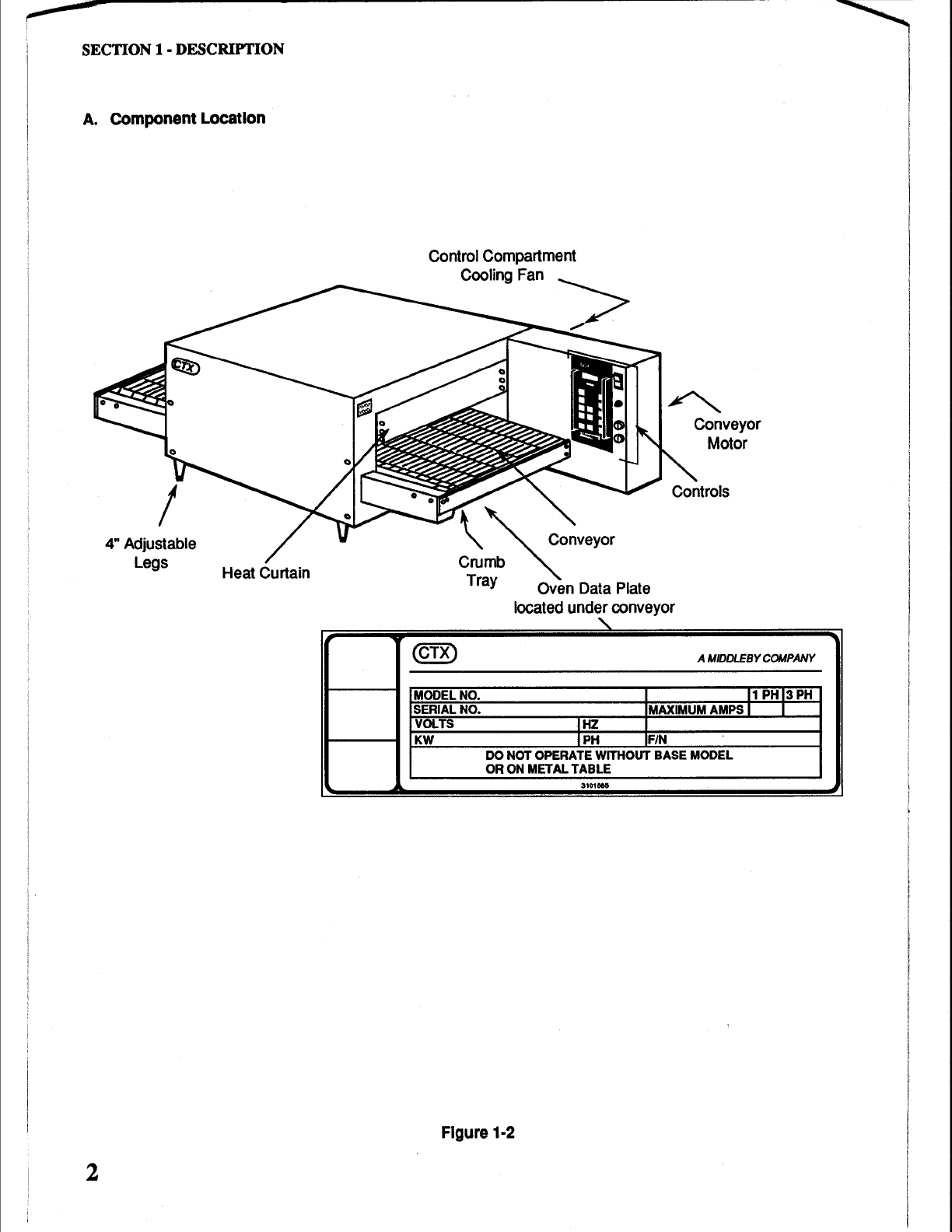
A.
Component Location ................................................................2
B.
Component
Function
................................................................3-4
C.
Oven
Specifications .................................................................
5-8
D.
Dimension
Drawings
................................................................7
SECTION
2
INSTALLATION ............................................................................9
A.
Inspect For Shipping
Damage
..................................................9
B.
Placement of
Oven
...................................................................9
C.
Unpacking
Oven
.......................................................................
10
D.
Uncrating
Oven
........................................................................
11
E.
Installing
Legs
..........................................................................
11
F.
Stacking
and
Mounting
Two
Ovens
..........................................
12
G.
Stacking a single
G-26
oven
over a Toastmaster C0-19
convection oven or a
Blodgett
CTB-1
convection
oven
........
13
H.
Conveyor
Belt
and
Temperature
Display
.................................
14
I.
Standoffs ............................................................................
15
J. Electrical Connection ................................................................
15
K.
Heat
Curtains ...........................................................................
16
L.
Exit
Tray ............................................................................
16
SECTION
3
OPERATION ............................................................................17
A.
Location of Controls .................................................................
17
B.
Control Operation
And
Programming
.......................................
18
C.
Cooking
in
a
CTX
Oven
...........................................................
25
1.
Infrared
Cooking
Technology.......................................
25
2.
Heat
Zoning
.................................................................
25
3.
General
"Rules
of
Thumb"
...........................................
26
4.
Cooking Trials ..............................................................
26
5.
Time
and
Temperature
Guide
......................................
27-30
6.
Loading
the
Conveyor..................................................
31
Production
Chart
..............................................................
32
SECTION
4
MAINTENANCE ............................................................................
33
.
A.
Cleaning the Cooling
Fan
Filter................................................
33
B.
Cleaning
the
Oven
Chamber
....................................................34
C.
Cleaning "Loose"
Parts
............................................................
35
D.
Cleaning the Exterior................................................................
37
E.
Spare
Parts
Kit .........................................................................37
SECTIONS
TROUBLESHOOTING
••••••.••••••..•••••..•••.••.•..•••.•.•.•••••...•••....••••....•••••••••
39
Troubleshooting Chart 1 -Oven
is
Dead
......................................
39
Troubleshooting Chart 2 - Conveyor
Does
Not
Run
.....................
39
Troubleshooting Chart 3 -
Conveyor
Runs
Full
Speed
.................
40
Error
Codes
............................................................................
40
SECTION
6
PARTS LIST ............................................................................
41
Heating
Elements
and
Thermocouple
.........................................
.41
Conveyor,
Control
Panel
and
Loose
Parts
...................................
42-,43
Conveyor Motor
and
Electrical
Components
................................
44-45
SECTION
7
ELECTRICAL
SCHEMATICS
&
WIRING
...........................................
47
Schematic
208/240VAC,
1
Ph,
50/60Hz.......................................
48
Wiring
Diagram
208/240VAC,
1
Ph,
50/60Hz
...............................49
Schematic
380VAC,
3
Ph,
50Hz
...................................................
50
Wiring
Diagram
380VAC,
3
Ph,
50Hz
...........................................
51
iii