5
6
7
1
1
1
Quick installation guide
Product warranty card
Velcro
NO Part Name Q’ty
1
2
3
4
1
2
4
4
Sensor
Valve package (valve and screw)
Tire pressure monitoring receiver
AA battery
VS-63W018 Contents
FCC Regulations
This tire pressure monitoring system has complied with Article 15 of the FCC regulatory
requirements of the USA, but it is still needed to pay attention to the following two items:
(1) Other harmful interferences may affect the system’s normal operation.
(2) Abnormal operation may cause the system to fail.
This equipment has been tested and found to comply with the limits for a Class B digital
device, pursuant to part 15 of the FCC rules. These limits are designed to provide
reasonable protection against harmful interference in a residential installation. This
equipment generates, uses and can radiate radio frequency energy and, if not installed and
used in accordance with the instructions, may cause harmful interference to radio
communications. However, there is no guarantee that interference will not occur in a
particular installation. If this equipment does cause harmful interference to radio or
television reception, which can be determined by turning the equipment off and on, the user
is encouraged to try to correct the interference by one or more of the following measures:
-Reorient or relocate the receiving antenna.
-Increase the separation between the equipment and receiver.
-Connect the equipment into an outlet on a circuit different from that to which the receiver
is connected.
-Consult the dealer or an experienced radio/TV technician for help.
FCC RF Radiation Exposure Statement:
This equipment complies with FCC radiation exposure limits set forth for an uncontrolled
environment. End users must follow the specific operating instructions for satisfying RF
exposure compliance. This transmitter must not be co-located or operating in conjunction
with any other antenna or transmitter.
Note: The product will not be guaranteed if user change or modify the hardware and
system design.
Warning
Important Safety Guide
System Warning
When the system displays a warning light and warning "beeps", you should immediately
slow down, stop in a safe location and check the tire condition, and immediately drive to
the nearest qualified tire maintenance garage to repair and make related in-depth
examination.
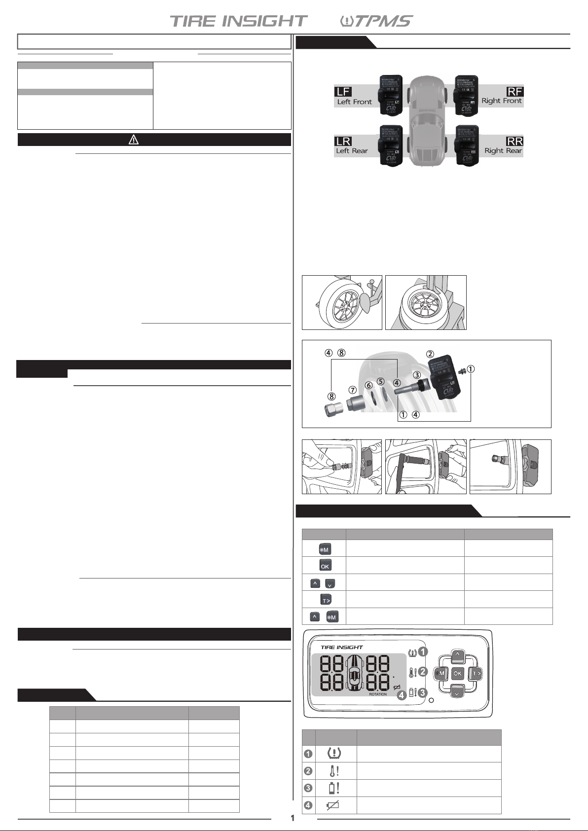
2.2 Sensor Assembly Process
Please follow the label on the sensor, install the sensor into the rims accordingly, it could
skip the “ID Learning” steps for each sensor!
2.1 Installation Location
1.Product Parts List
2.Sensor Installation
Product Warning
1.Do not operate a TPMS receiver while driving. The company is exempt from all
consequences because of driver’s careless and improper operation.
2.The system adopts the wireless transmissi of signals. In some special circumstances,
interference or erroneous methods of operation or installation method errors may
cause weaker signal or its inability to receive signals. If the insulation adhesive sticker
of the windshield contains metal material, it will be likely to affect reception conditions.
If the tire pressure and temperature readings on the TPMS receiver are displayed as
---, this condition represents the receiver cannot receive signals emitted by the
sensors. Drive the vehicle away from the current location (nearby there may be signal
interference) or drive the vehicle to a tire shop to check, or return the TPMS receiver to
distributor for repair. If the battery status of the TPMS sensors inside the tire is low
(because abnormal conditions continue to occur, the battery may make the TPMS
sensors continuously emit signals to warn the driver, so that battery life is shorter than
the normal life), please go as soon as possible to the specified service stations to
confirm whether the TPMS Sensors need to be replaced.
3.Please change the Receiver’s dry battery or sensor while the Receiver’s dry battery
power is low or Sensor Low battery warning is alarm, or it may cause the TPMS thus
cannot be operated and alarm normally. You will take all risks and responsibilities for
this!
4.Temporary resealing or re-inflation products containing internal sealants or propellants
in any tire assembly may adversely affect the operation of the sensor/transmitter. The
product manufacturer does not assume any liability as a result of these.
System Installation
The wireless TPMS needs to be installed by qualified personnel in accordance with
installation manual to enjoy related warranty. If improper assemble or disassemble process
damages the sensor, it will not be covered by warranty.
Reminder: annual periodic inspection for the "sensor valve" is proposed, which should be
replaced immediately if damaged, in order to avoid air leakage.
Fig 1 Fig 2
1.Screw
2.Sensor
3.Rubber washer
4.Valve core
5.Washer
6.Washer
7.Nut
8.Valve cap
~Outside of the rim
~Inside of the rim
Fig 3
Fig 4 Fig 5 Fig 6
Quick Installation Guide
4-wheel Battery TPMS System
Warning
FCC Regulations
Product Warning
System Installation
Important Safety Guide
1.Product Parts List
2.Sensor Installation
2.2 Sensor Assembly Process
2.1 Installation Location
3.Installation of Tire Pressure Monitoring Receiver
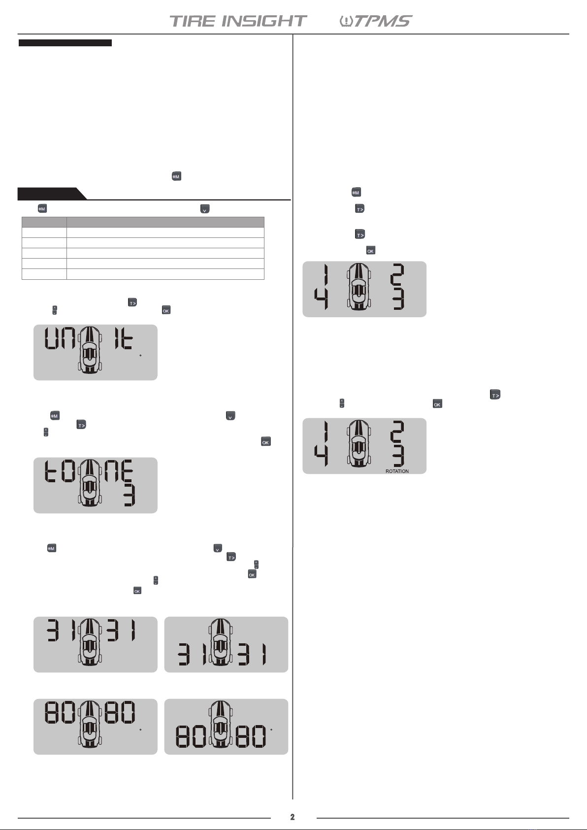
4.Setting Items
4.1 Tire Pressure Unit Setting
4.2 Volume Setting
4.3 Tire Pressure Standard and Temperature Warning
Value Setting
4.4 ID Learn Setting
4.5 Tire Position Rotation Setting
3.3 Recommend the Receiver Mounting Position
3.2 Warning Light Symbol
3.1 Buttons Function Introduction
Function key Normal mode Setting mode
+
Backlighting and enter the function
setting mode (hold for 3 seconds) Leave function setting mode
Mute the warning audio Save the setting
Up and down selection/
value adjustment
Switch to tire temperature mode for
10 seconds Unit setting or right button
Set the backlight to be always on/off
3.1 Buttons Function Introduction
3.Installation of Tire Pressure Monitoring Receiver
psi
Bar
C
SETTINGS LEARNING
(Fig 1) Loosen the tire. Fix both sides of the tire and press, and make it bulge.
(Fig 2) Remove the tire. The valve faces the mounting arm in the one o’clock direction,
remove the tire.
(Fig 3) Remove the sensor. Loosen the fixing screw, allow the sensor separate from the
valve, and release the nut to take it apart from the valve.
(Fig 4) Install the sensor and valve. Insert the valve through the rim hole, fix the screw to
secure the valve and sensor by 2 Nm in torque, attach the sensor body to the inner
surface of the rim by adjusting the angle of the sensor body.
(Fig 5/6) Install valve to the rim hole. Guide the washer into the valve, and fix the nut by 4
Nm in torque, then tighten the cap.
Note: Mount the tire. Grip the rim edge, and the valve is opposite to the mounting arm, avoid
hitting the sensor during arm operation.
3.2 Warning Light Symbol
Light SymbolNo. Abnormal Light Message
Alarm for excessive high tire temperature
Warning for low battery in TPMS sensor,
need to replace new sensor
Warning for low battery in receiver,
need to replace new battery
Alarm for excessive high/low tire pressure