CubeWORKS CubiSens TS100 User manual

CubiSensTM TS100
Wireless Temperature Sensor
User Manual
© 2020 CubeWorks. All rights reserved.

CubiSensTM TS100 User Manual
v1.7
© 2020 CubeWorks. All rights reserved. Page 2 / 15
Table of Contents
Introduction ..................................................................................................................................................3
Important Notes before Using the TS100.....................................................................................................3
TS100 Communication Kit.............................................................................................................................4
1. What’s in the Box..............................................................................................................................4
2. User System Requirements...............................................................................................................5
3. Hardware Assembly .........................................................................................................................5
4. Ethernet Configuration .....................................................................................................................6
5. Driver & GUI Software Installation ...................................................................................................9
Using the TS100 ..........................................................................................................................................11
1. Overview.........................................................................................................................................11
2. Optical Communication ..................................................................................................................11
3. Starting Measurement....................................................................................................................12
4. Stopping Measurement ..................................................................................................................12
5. Viewing Measured Data Real-Time.................................................................................................13
Technical Specifications..............................................................................................................................14
1. TS100 Technical Specifications .......................................................................................................14
2. CSG100-A9 CubiSens™ Gateway Tech Specs..................................................................................15

CubiSensTM TS100 User Manual
v1.7
© 2020 CubeWorks. All rights reserved. Page 3 / 15
Introduction
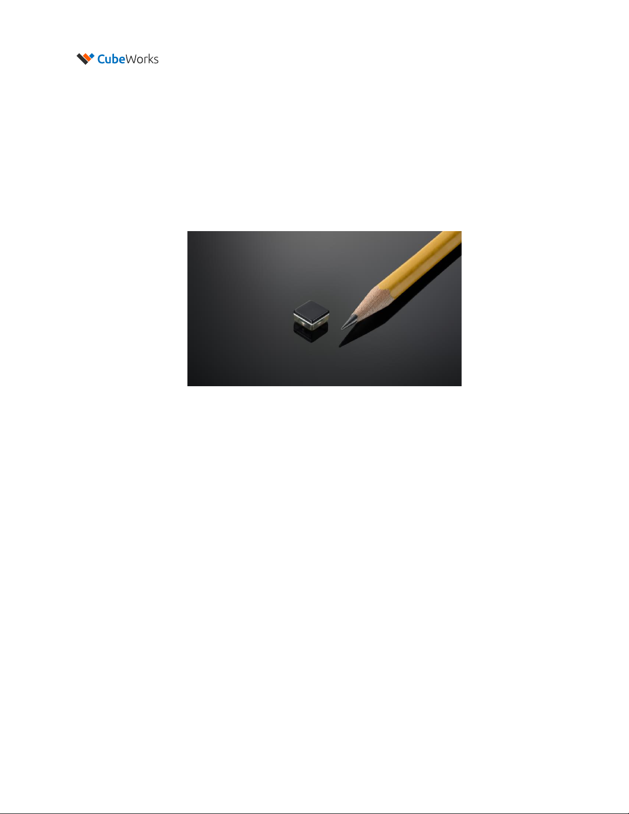
CubiSensTM TS100 Wireless Temperature Sensor (TS100 in short) is a millimeter-scale wireless sensor for
accurate, real-time temperature measurement. Measuring only 7.5 x 7.5 x 4.2 mm, the TS100 is capable
of transmitting up to 100m in distance and last up to 2 years in sensing operation. The device is packaged
in bio-compatible epoxy and coated with parylene, making it ideal for implanting in animal models. The
TS100 Communication Kit includes a Windows-compatible GUI software, which allows the user to start
operations, stop operations, and view the received data. This document serves as the user manual for the
TS100, as well as an installation manual for setting up the TS100 Communication Kit.
Important Notes before Using the TS100
•Abrupt Temperature Change During Measurement:Measurement interval must be set to ensure
<20°C change between successive measurements. For example, if the TS100 needs to be abruptly
dropped into a hot or cold liquid during measurement resulting in a rapid temperature change of 40°C,
the measurement interval should be set to no more than 5 seconds, which is about 1/2 the thermal
response time of the unit.
•Battery Life: The TS100 operation lifetime varies significantly depending on the exposed temperature
and measurement interval. Before starting measurement operation, please refer to Figure 1 of “TS100
Technical Datasheet”to select the appropriate measurement interval.
•Temperature Exposure:The TS100 is designed for indoor environments and animal implants (10-
55˚C). Optical communication must be performed at room temperature (20-30˚C) in an indoor
environment. Please refer to Technical Specifications section for details on other temperature limits.
Please allow at least 5 minutes for the unit to acclimate to a new temperature environment before
initiating optical communication in case of an abrupt temperature change.
•Manual Handling:Each unit is coated to protect the electronics from manual handling. However,
directly grabbing the unit in certain ways can temporarily shift radio frequency of the integrated
antenna and hamper wireless communication. Also, handling with sharp objects that can
compromise the coating should be avoided.
Figure 1. CubiSensTM TS100 Wireless Temperature Sensor

CubiSensTM TS100 User Manual
v1.7
© 2020 CubeWorks. All rights reserved. Page 4 / 15
TS100 Communication Kit
1. What’s in the Box
The TS100 Communication Kit consists of:
1. CSG100-A9 CubiSens™Gateway
2. Gateway Antenna
3. CubiSensTM Optical Programmer
4. USB to Ethernet adapter
5. Ethernet cable
6. Micro USB cable
7. 5V power adapter
Figure 2. TS100 Communication Kit Example Setup
1 4
2
5
3 7
6

CubiSensTM TS100 User Manual
v1.7
© 2020 CubeWorks. All rights reserved. Page 5 / 15
2. User System Requirements
For proper operation of the TS100 Communication Kit, user needs access to a Windows computer with 2
available USB ports. Details on minimum system requirements is shown below.
Minimum User System Requirements
Operating System
Windows 7, 8, 10
Memory
1GB
Processor
1GHz
Software Framework
Microsoft .NET 4.7.2
Storage
500MB available disk space
Ports
2 available USB 2.0 (or higher) ports
3. Hardware Assembly
1. Screw in the antenna to the CSG100-A9 CubiSens™Gateway as shown in Figure 5.
2. Connect the 5V power adapter to the CSG100-A9 Gateway and plug it into a power outlet.
3. Connect the ethernet cable to the CSG100-A9 Gateway and to the ethernet-to-USB adapter.
4. Connect the ethernet-to-USB adapter into a computer’s USB port.
5. Verify that the Power light is lit on the gateway, and that the Activity light is blinking.
6. Connect the CubiSensTM Optical Programmer to the same computer that the CSG100-A9 Gateway
is connected to with the provided micro-USB cable.
7. Verify that two blue LEDs light up in the programmer, and that one starts blinking, as shown in
Figure 5.
8. The kit is now ready for ethernet configuration and software installation.
Note: The gateway will become warm to the touch. Please keep the top and sides clear when it is powered
to allow proper ventillation.
Figure 5. TS100 Communications Kit Hardware Connections

CubiSensTM TS100 User Manual
v1.7
© 2020 CubeWorks. All rights reserved. Page 6 / 15
4. Ethernet Configuration
The USB-to-Ethernet adapter needs to be configured as follows (Windows 10 shown as example):
1. Verify that the USB to Ethernet adapter is connected to the computer using an available USB port.
2. Press the windows key on the
keyboard, then start typing
“ethernet” until you see the
option for “Ethernet settings”.
Select that and press enter or click
on it.
3. A new window, “Ethernet” will
open. Click on “Change adapter
options”, which may appear below
or to the right of the identified
networks.

CubiSensTM TS100 User Manual
v1.7
© 2020 CubeWorks. All rights reserved. Page 7 / 15
4. In the “Network Connections”
window look for connections
labeled “Ethernet”. If there are
multiple ethernet connections
find the one with the subtitles
“ASIX AX88179…” or “Realtek
USB..”
Right click on that connection to
bring up another menu.
5. In the context menu which
appears choose “Properties”.

CubiSensTM TS100 User Manual
v1.7
© 2020 CubeWorks. All rights reserved. Page 8 / 15
6. In the new window that opens
click on text “Internet Protocol
Version 4(TCP/IPv4)” to select that
line. Be careful not to click on any
checkboxes. With “Internet
Protocol Version 4(TCP/IPv4)”
selected click on the button
“Properties”.
7. Choose “Use the following IP
address:” and set the IP address to
192.168.10.1. The subnet mask
should automatically set itself to
255.255.255.0, but if not then set it
to that value. Verify that the
settings are as follows, then click
“OK”.
8. Click “OK” in the ethernet
properties window, then close all
the windows opened during this
process.
The ethernet configuration for the
CubiSens™Gateway is now
complete.

CubiSensTM TS100 User Manual
v1.7
© 2020 CubeWorks. All rights reserved. Page 9 / 15
5. Driver & GUI Software Installation
The GUI software is used to communicate with the TS100 through the optical programmer and gateway,
providing a user interface for controlling the device and downloading its data. The software and driver
need to be installed as follows:
1. Run “CDM21228_Setup.exe” in the installation kit and follow its installation instructions. This will
allow the computer to send commands to the TS100 via the optical programmer.
2. Run “TS100GUI_Setup.exe” in the installation kit and follow its installation instructions. When
asked “Do you want to allow this app from an unknown publisher to make changes to your device?”
select “Yes”.
3. Start the TS100 GUI application by doing
one of the following:
-Double-click the desktop icon
-Click the Windows menu button,
scroll to “CubeWorks”, click on it,
then click on “TS100 GUI”
-Click the Windows menu button and
type “TS100” in the search bar until it
appears, then click on it.
Note: The installer might prompt for
installation or update of Microsoft .NET
software. This will only happen once,
please follow the prompts to download
and install the update.
Desktop shortcut:
Windows search:
4. Once the GUI software launches and if
the ethernet setting was configured
correctly according to the instructions in
Section 4, the connection to the
CubiSensTM Gateway will automatically
established. “Gateway connected”
message will be displayed.

CubiSensTM TS100 User Manual
v1.7
© 2020 CubeWorks. All rights reserved. Page 10 / 15
5. The green blinking status light next to
the IP address of the gateway indicates
connection status to the gateway.
6. The opening screen shows the settings.
The COM Port of the Optical Programmer
must be selected by clicking on the Serial
Port selection dropdown menu.
Note: If multiple ports are available,
disconnect the micro USB cable from the
Optical Programmer, select “Rescan Ports”
from the selection box, and see which port
disappears. Then reconnect the USB cable
to the Optical Programmer, select “Rescan
Ports” from the selection box, and see
which new port is available. Select the
port that appears.
7. The GUI is now ready to be used.
Note: The GOC_DELAY and GOC_SPEED
values will be automatically filled with
suitable settings, and do not need to be
adjusted.

CubiSensTM TS100 User Manual
v1.7
© 2020 CubeWorks. All rights reserved. Page 11 / 15
Using the TS100
1. Overview
TS100 Wireless Temperature Sensor uses optical communication for receiving commands from the user
and for RF communication transmitting data and status. The optical communication is intended for short-
range configuration and command, whereas the RF communication can be received from up to 100m line-
of-sight. When implanted or operated in an environment with obstructions, RF communication distance
can be significantly reduced.
2. Optical Communication
To send a command to a TS100, TS100 device should be placed on the communication slot of the
CubiSensTM Optical Programmer with the clear side facing down, as shown in Figure 7. This ensures that
the TS100’s optical sensor faces the LED of the programmer. Each time a command button is clicked on
the GUI, an optical packet is transmitted, which takes 1-2 seconds. The buttons on the GUI will be disabled
during the optical transmission.
Important: The TS100 should be placed with the clear side facing down, as shown in Figure 7.
Important: The TS100’s core temperature should be at room conditions (20oC - 30oC) for communication.
If it has been exposed to extreme temperatures, please allow at least 5 minutes for it to acclimate to room
temperature before attempting communication.
Incorrect
Incorrect
Correct
Figure 7: Orientation & Placement of TS100 for Optical Communication

CubiSensTM TS100 User Manual
v1.7
© 2020 CubeWorks. All rights reserved. Page 12 / 15
3. Starting Measurement
To command the TS100 to start measuring temperature with a desired measurement interval:
1. Place the TS100 on the optical programmer.
2. Select the tab “Control” in the TS100 GUI.
3. Set the measurement interval.
4. Click the “Start Measurement” button.
5. After 3-4 seconds, the TS100 will reply with a “Measurement Started” message, the current
battery state, and starts measuring at the set interval.
6. The measured data will be displayed as a “Check-in” message from the particular TS100 unit,
identified by its “Chip ID”.
Note: The TS100 will start measuring temperature values until the user stops it using optical
communication. Refer to the TS100 Technical Datasheet for details on battery life.
4. Stopping Measurement
1. Place the TS100 on the optical programmer.
2. Click on “Stop Operation” to stop ongoing measurement operation and the TS100 will report its
current battery state.
Note: This command can also be used when the TS100 is not in measurement mode, for instance, to check
what the battery state is or to identify its Chip ID.
Figure 8: Starting & Stopping Measurement

CubiSensTM TS100 User Manual
v1.7
© 2020 CubeWorks. All rights reserved. Page 13 / 15
5. Viewing Measured Data Real-Time
Any measurement data from the TS100 received by the Gateway will be displayed in real-time on the GUI
log as part of the “Check-in” message, and also as a datapoint in the “Plot” tab of the GUI, as shown in
Figure 9. The plot may be used to examine measurement data. User can click on the plot to control it.
After clicking, zooming can be accomplished with the mouse scroll wheel or Page Up and Page Down
buttons on the keyboard. The arrow keys or the right mouse button can be used to move the graph and
examine areas of interest.
The received data is also saved in CSV format under “My Documents\CubeWorks\” folder with a file name
corresponding to the TS100 device ID. The file location can be configured in the “Settings” tab. The CSV
formatted data file includes the device ID, timestamp, raw data, and converted data.
Figure 9: “Plot” Tab of the GUI Showing Real-time Data from Multiple TS100 Devices

CubiSensTM TS100 User Manual
v1.7
© 2020 CubeWorks. All rights reserved. Page 14 / 15
Technical Specifications
1. TS100 Technical Specifications
Please refer to the “TS100 Technical Datasheet” for full details on the technical specifications. Below are
key specifications for TS100.
TS100 Device Specifications
Dimensions (W x L x H)
7.5 x 7.5 x 4.2 mm
Weight
0.5g
Thermal Reaction Time
τ: 11.7 (1-e-t/τ)
Thermal Mass
TBD
Operation Temperature
10˚C - 55˚C
Optical Interface Temperature
20˚C - 30˚C
Storage Temperature
10˚C - 30˚C
Battery Lifetime
1 min interval: 5 weeks
5 min interval: 26 weeks
30 min interval: 2 years
Storage Lifetime
1 Year
Wireless Communication
Optical RX, RF TX
Packaging Material
Biocompatible Epoxy and Parylene Coating
TS100 Temperature Sensor Specifications
Resolution
0.05°C
Inaccuracy, 25-45°C
±0.1°C
Inaccuracy, 10-55°C
±0.2°C
Measurement Interval
5s to 1 Hour (Configurable)
Measurement Timing Accuracy
1%

CubiSensTM TS100 User Manual
v1.7
© 2020 CubeWorks. All rights reserved. Page 15 / 15
2. CSG100-A9 CubiSens™Gateway Tech Specs
The CSG100-A9 CubiSens™ Gateway receives the RF transmissions from the TS100 sensors, interprets
them, and provides them to the software.
CSG100-A9 CubiSens™Gateway Specifications
RF Receiving Frequency
915 ±10MHz
Size
141 x 81 x 33mm
Weight
400g
Power Source
5V DC
Power Consumption
10W
CSG100-A9 CubiSens™ Gateway
Table of contents
Popular Accessories manuals by other brands

HB Products
HB Products HBX Vapor Quality sensor Installation and configuration guide

Vernier
Vernier RH-BTA manual

Rolbak
Rolbak Gold EDITION Assembly instructions

Kampa
Kampa Rally 200 Instructions & care manual

Dometic
Dometic POWER AWNING PRO Installation and operation manual

Celsicom
Celsicom TH500 user manual