Cubis stakkabox User manual

INSTALLATION GUIDE
STAKKAbox™ Range
General guide
www.cubis-systems.com
+44 (0)28 38 313 100

INTRODUCTION
2
This guide addresses the acceptable methods and details for installation of STAKKAbox™ Access Chambers. The purpose is to serve as
a guideline, and is not intended for any specic construction project. It is understood there are alternative ways that might be required
and/or recommended based on site or project conditions. CUBIS Industries reserves the right to alter these guidelines and encourages
contact with the factory or its representatives to review any possible modication to these notes prior to commencing installation. CUBIS
Industries makes no express or implied warranty or guarantee of the techniques, construction methods or materials identied herein.
The customer shall comply with all laws, regulations, codes and orders of any authority having jurisdiction over the customer and which relate
to the customer’s installation, maintenance and use of CUBIS products. If the customer’s installation or use of any products contravenes any
such laws, regulations, codes or orders of such authorities, the customer shall be responsible for the violations thereof and shall bear the costs,
expense and damages attributable to its failure to comply with the provisions of such laws, ordinances, rules, regulations, codes or orders.
Reproduction of the material herein is not permitted without the written consent of CUBIS Industries.
NOTES ON APPLICATION
This installation guide is for STAKKAbox chambers being installed in areas classed as
Groups 1, 2, 3, or 4 in accordance with European Standard EN 124 :1994.
Group 1: A15 Classication
Areas which can only be used by pedestrians and pedal cyclists.
Group 2: B125 Classication
Footways, pedestrian areas and comparable areas, car parks or parking decks.
Group 3: C250 Classication
Areas which when measured from the kerb edge extend a maximum of 0.5m into the carriageway and a
maximum of 0.2m into the footway.
Group 4: D400 Classication
Roadways, carriageways and areas used by fast moving vehicular trac.
This means that CUBIS chambers can, depending on how they are installed be situated in either the footway or the road.
Both situations are addressed within this document.

3
EQUIPMENT AND ADDITIONAL MATERIALS
In addition to the STAKKAbox™ supplied, in order to complete an installation you will need the following:
EQUIPMENT
1. The means of excavating a hole; mechanical digger, pneumatic hammer etc. depending on the ground conditions and size
of chamber being installed.
2. Shovel or spade.
3. Means of compacting base and surrounding material.
Please refer to the “Specication for the Reinstatement of Openings in Highways - Appendix A8”
4. Builders trowel.
5. Straight edge/level.
6. Handsaw.
Furthermore if duct entries are to be cut on site:
7. Hole saw (Sized to the outside diameter of the duct to be installed).
8. A power drill (Compressed air, battery or 110v).
9. Bracing if type and size of chamber requires (See Table 1).
Materials
1. Base materials (See Table 1).
2. Backll material (See Table 1).
3. Bedding mortar/resin epoxy mortar.
FRAME AND COVER
A frame and cover must be installed, specied to the correct loading as dictated by European standards or any other relevant authority.
CUBIS Industries manufacture a range of covers and frames engineered to work in conjunction with its chambers. Covers and frames that are
not supplied by CUBIS should be agreed to be t for purpose prior to installation as this might adversely aect the quality of the installation.
HEALTH AND SAFETY
In areas where the public have access, the site should be properly signed and guarded in accordance with the Safety at
Street Works and Road Works code of practice (NRSWA 1991) or equivalent national standard.
Additionally, all other safety precautions required by legislation, the customer and as specied by the contract, the Local
Authorities, other landowners and the Police should be observed at all times.
Before any excavation takes place, all necessary precautions to locate/protect buried services in the location of the
chamber should be taken.
This document is a general installation guide for the following product ranges: STAKKAbox™ ULTIMA, STAKKAbox™ MODULA, STAKKAbox™
Fortress Footway, STAKKAbox™ Fortress Carriageway.

4
INSTALLATION PROCEDURE
Area of Excavation
1. Mark the extremity of the excavation on the ground. Placing the bottom
section of the chamber on the ground mark around it, allowing either
the minimum thickness of backll as stated in Table 1, or the width of the
compaction plant, whichever is the greater.
The Hole
2. Excavate the hole to the correct depth. The depth of the hole should
measure from nished ground level minus the thickness of the frame &
bedding mortar according to the level specied by the frame and cover
installation, chamber depth and the required base depth (see Table 1 for
base depths).
The Base
3. Compact the bottom of the excavation using a suitable compaction device, making sure that it is level. If there are any “soft areas” these
should be excavated and lled with MOT1 stone or other approved materials, compacted as per the requirements of “Specication for the
Reinstatement of Openings in Highways - Appendix A8” or equivalent national standard.
4. Construct the base using the necessary materials.
4.1. If a drain is required in the chamber it should now be installed as per the client’s specication.
4.2. For compacted stone, level the stone with the shovel and compact as per the requirements of “Specication for the
Reinstatement of Openings in Highways - Appendix A8”.
4.3. For a concrete base, level the C40 concrete and compact as per the requirements of“Specication for the Reinstatement
of Openings in Highways - Appendix A8”. For bases that require reinforcing mesh the base should be constructed in 2 levels, with the
mesh being placed in the middle.
5. The bottom ring section is now carefully positioned on the base. If the chamber system does not have a preformed base,
then the ring should be gently tapped so that it beds down into the base by approximately 10mm. The correct orientation of the chamber
ring is with the horizontal lip to the bottom. Check that the ring is level and at the correct depth. If a concrete base is being used, the
concrete can be oated to give a smoother nish.
The Chamber Walls
6. The additional wall sections are then installed. Make sure that each section is properly inserted to ensure there are no gaps between
Duct Entries
7.Chambers can either have the duct entries factory drilled or can be formed on site.
7.1.For factory drilled chambers remove the duct caps as required.
7.2.Site formed duct entries are best created using a hole-saw and drill, if these tools are
not available then the opening can be formed by using a hand saw or disc cutter to form
a square hole. When the duct is tted the gap between the cut and the duct should be
lled using mortar.
7.3.If using pre-formed bell mouths or chamber entry connectors these can be tted now.
7.4.Insert the ducts into the holes.
7.5. Duct entries should not be formed in the bottom section or the top two sections
without prior approval of CUBIS Industries.
7.6.Duct entries should not be cut within 50mm from the corner.
7.7.The distance between duct entries should be a minimum of half the duct diameter from edge to edge.
7.8. The accumulative diameter of all of the ducts should not constitute more than 20% of the total circumference of the access
chamber section.
7.8.1.In the event of duct entries constituting more than 20% of the total circumference of a section, a structural C40 surround
should be installed up to the uppermost duct entry section ring.

5
Overbuilding Existing Services
8. Where chambers are required to be built over existing services, STAKKAbox can easily accommodate this by either:
8.1. Cutting a duct entry in the appropriate ring section as previously described and then with a hand saw cutting from the bottom of
the ring to make an open ended arch.
8.2. Alternatively, after the duct entry has been formed, the ring can be cut longitudinally and reassembled around the existing
duct.
8.3. In both cases it is important that a complete ring is installed either side of the cut ring section.
Wall Furniture & Security Systems
9. Wall furniture can be installed at this stage if not already factory tted.
9.1. Mark the position of the furniture as required by the clients’specication on the chamber walls, drill 11mm holes and x the furniture with
the bolts supplied.
9.2. If using Footway Fortress, the wall bears simple hang in the preformed slots.
9.3. Wall furniture and security systems can be retrotted at a later date on most chambers. For specic details please contact
CUBIS directly.
www.cubis-systems.com

6
INSTALLATION PROCEDURE
Bracing
10. On certain chambers cross bracing is required. See
Table 1 for details.
10.1. If timber bracing is required this should be
supplied with the chamber. Make sure that the bracing
isverticalandplumbandlocatedinthecorrectposition.
10.2. On larger chambers “Acrow” props are used as
bracing.
These are not supplied by CUBIS. Timber footplates
should be used to disperse the loads evenly over the
chamber. See Table 1 for spacing details.
Backlling
11. With the chamber installed to its nished depth, duct entries formed, furniture tted and if required suitable bracing installed, the backll
surround of the chamber can now take place. Backlling is formed in layers and should be completed to the top of the chamber, or in the
case of a roadway construction to the underside of the blacktop construction. Refer to Table 1 for the recommended backll material and
required width of material.
Refer to “Specication for the Reinstatement of Openings in Highways - Appendix A8” for the depth of layers and number of
passes required for the selected material and compaction method.
11.1. If timber bracing is being used, this should be raised along with the backlling to ensure that there is adequate support for the chamber
wall section that is being compacted against.
11.2. If Acrow props are required these can be left in position until the backll and compaction are completed and the material has adequately
cured.

7
Final Adjustment
12. If the chamber height has been miscalculated and the levels can not be altered by adjusting the bedding of the frame, it is possible to cut
the top section of the chamber horizontally to correct the level.
12.1. Simply mark the chamber section that requires adjustment and cut by either using a handsaw or a disc cutter.
12.2. The required section can then be bedded onto the next section using the standard processes.
12.3. The voids in the top section should now be lled with lean mix concrete to give a solid base for the frame to be bedded on.
Frame and Cover
13. Once the chamber is backlled the frame and cover can be tted.
13.1. Place the frame on top of the chamber to check that there is adequate space for a mortar
bed. The depth of acceptable bed can vary between client so referral to the appropriate
requirements should be taken. Generally mortar beds can range from 10 to 40mm in
thickness. Pack the frame to the required height using suitable approved materials and
check that the frame is in a coplanar state.
13.2. Remove the frame and apply the mortar bed. This should be approximately 10mm
higher
than required and 25mm greater than the spread of the underside of the frame.
13.3. Carefully position the frame on to the mortar bed, taking care that the inside faces of
the frame line up with the edges of the chamber. If using a rising frame this should
happen automatically.
13.4. Gently tap the frame into the mortar bed until the correct level is achieved, always
checking that the frame is in a coplanar state.
13.5. Remove any excess mortar that has squeezed into the chamber and trowel mortar over
the exterior anges/grout bars at a 45° angle away from the frame.
13.6. After the mortar has suciently cured the covers can be installed. (The use of epoxy
resin
mortars can be used and these can have a dramatic eect at reducing curing times.
Please check with client about approval before use).
Reinstatement
14. The nished surface can now be reinstated around the chamber.
Other Notes
15. STAKKAbox™ access chambers can be supplied as a xed-depth unit which will require suitable lifting requirements if planned to be
lifted as a single unit. Lifting eyes, frames or other arrangements can be installed in-factory to accommodate mechanical lifting.

8
APPENDIX
Specication for the Reinstatement of Openings in Highways - Appendix A8
Table A8.1
Weight Category
Cohesive Material (less than 20%
granular content)
Granular Material
(20% or more granular content
including cement bound material)
for compacted thickness up to for compacted thickness up to
100mm1 50mm 200mm1 00mm1 50mm 200mm
Vibrotamper
50 kg minimum 48 #N P4 8N P
Single Drum
1000-2000 kg/m 8 NP NP 6N PN P
2000-3500 kg/m 36N P3 57
Over 3500 kg/m 346 # 346
Twin Drum
600-1000 kg/m NP NP NP 6N PN P
1000-2000 kg/m 48N P 36N P
Over 2000 kg/m 235 # 234
1400-1800 kg/m2N PN PN P5 NP NP
Over 1800 kg/m236N P3 57
Notes:
1
2
3
4
Vibrotamper
25kg minimum
Percussive Rammer
10kg minimum

9
TABLE 1
Product
EN 124
Group
Recommended
minimum Cover
Class*
Maximum
Chamber
Depth
(mm)
Excavation Footprint Base Material Bracing Backfill Additional Information.
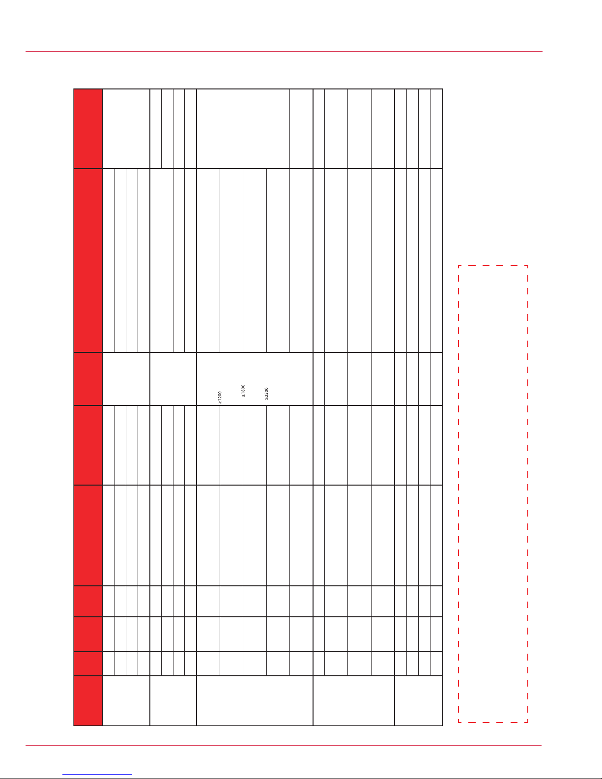
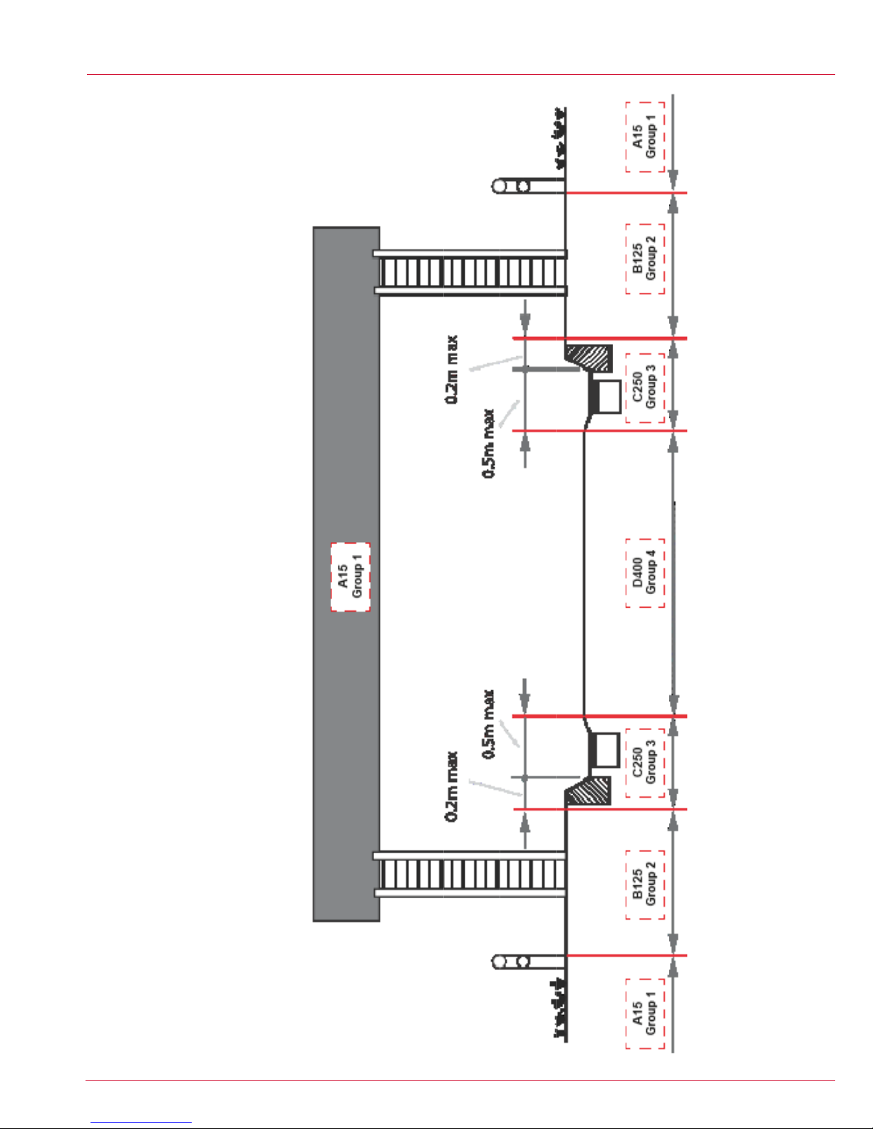
1A15 1200100mm or width of compacting equipment50mm of compacted stone (MOT1) Compacted MOT1 stone, or as dug material if of a granular type.
2B125 1200100mm or width of compacting equipment100mm of compacted stone (MOT1) Compacted MOT1 stone or lean mix concrete.
3 C250 1200150mm or width of compacting equipment150mm of lean mix concrete (C40) Minimum 150mm C40 concrete
4 D400 2000200mm or width of compacting equipment 150mm of lean mix concrete (C40),
reinforced with A393 mesh.Minimum 200mm C40 concrete
1A15 1200100mm or width of compacting equipment50mm of compacted stone (MOT1)
2B125 1200100mm or width of compacting equipment100mm of compacted stone (MOT1)
3 C250 1200150mm or width of compacting equipment150mm of lean mix concrete (C40) Minimum 150mm C40 concrete
4 D400 2000200mm or width of compacting equipment 150mm of lean mix concrete (C40),
reinforced with A393 mesh.Minimum 200mm C40 concrete
1A15 2400150mm or width of compacting equipment50mm of compacted stone (MOT1) Sidewall length < 1500mm As dug if granular is ok, otherwise compacted MOT1 stone.
Sidewall length between 1500 and 2500mm compacted MOT1 stone.
Sidewall length > 2500mm minimum 150mm C40 Concrete
2B125 2400150mm or width of compacting equipment100mm of compacted stone (MOT1) Sidewall length < 2500mm compacted MOT1 stone
Sidewall length > 2500mm minimum 150mm C40 concrete
3 C250 2400150mm or width of compacting equipment150mm of lean mix concrete (C40) Sidewall length < 2500mm compacted MOT1 stone
Sidewall length > 2500mm minimum 150mm C40 concrete
4 D400 2400 200mm or width of compacting equipment 150mm of lean mix concrete (C40),
reinforced with A393 mesh. Minimum 200mm C40 concrete
5E600 2400200mm or width of compacting equipment
250mm of lean mix concrete (C40),
reinforced with 2 layers A393 mesh
equally spaced.
Minimum 250mm C40 concrete
1A15 1200100mm or width of compacting equipment50mmof compacted stone (MOT1) Bracing required on
chambers with side wall Compacted MOT1 stone, or as dug material if of a granular type.
2B125 1200100mm or width of compacting equipment100mm of compacted stone (MOT1)
Bracing required on
chambers with side wall
lengths greater than
600mm.
Compacted MOT1 stone or lean mix concrete.
3 C250 1200150mm or width of compacting equipment150mm of lean mix concrete (C40)
Bracing required on
chambers with side wall
lengths greater than
600mm.
Minimum 150mm C40 concrete
4 D400 2000200mm or width of compacting equipment 150mm of lean mix concrete (C40),
reinforced with A393 mesh.
Bracing required on
chambers with side wall
lengths greater than
600mm.
Minimum 200mm C40 concrete
1A15 2000100mm or width of compacting equipment50mm of compacted stone (MOT1) No requirement for
bracing. Compacted MOT1 stone
2B125 2000100mm or width of compacting equipment100mm of compacted stone (MOT1) No requirement for
bracing.
Compacted MOT1 stone or in areas where additional stability is required lean mix
concrete can be used.
3 C250 2000150mm or width of compacting equipment150mm of lean mix concrete (C40) No requirement for
bracing. Minimum 150mm C40 concrete
4 D400 2000200mm or width of compacting equipment 150mm of lean mix concrete (C40),
reinforced with A393 mesh.
No requirement for
bracing. Minimum 200mm C40 concrete
Double bracing, equally
spaced
mm single central
bracing, required in both
directions.
mm double
bracing at equal
spacing.
mm bracing at
600mm spacing using
acrow props, both
horizontally and vertically
.
Minimum 100mm C40 concrete
*Cover Class,
r
efers to recommended minimum frame & cover for EN124 Group, backfill r
equirements are as per EN124 Group, see diagram xxx for reference
Footw
ay Fortress
Carriagew
ay
Fortress
M
odula (Sidew
all
upto 1200mm)
Modula (Sidew
all
greater 1200mm)
Ultima
Hydrant Sections require only a
granular backfill. Final adjustment is
not necessary, 25mm sections
available. Split base/dog kennel
arrangment around infrastructure.
TSSL base section do not require to
be concreted, minimum depth of
450mm upto 900mm
French Telecom
SNCF
Motorway Communications
approved, total system available from
sump base, bracketry and cover.
Bracing required on
chambers with side wall
lengths greater than
600mm.
It is key to note that the chamber backfill conditions relate to where the chamber is installed (EN124 Group).
Example
- If an ULTIMA
Chamber 1310 x 850 x 1050 deep is to be installed in the footpath (Group 2) but
with a D400 Ductile iron frame and cover. This should be installed as a group 2 Chamber i.e. base - 100mm
compacted MOT TYPE 1, backfill - 150mm compacted MOT
Type1.

10
DIAGRAM 1

11
DIAGRAM 2
Typical detail of a hard shoulder showing the location of some installation groups.

Contact us:
Head Ofce: 4 Silverwood Industrial Estate, Lurgan,
Co. Armagh, BT66 6LN, Northern Ireland
Telephone: +44 (0)28 38 313 100
Email: [email protected]
Web: www.cubis-systems.com
v.1.3
01/02/2016
Table of contents
Popular Plumbing Product manuals by other brands

Elkay
Elkay ELUH2317 Series installation instructions

Glacier bay
Glacier bay 67780-0001 Installation and care guide

IKEA
IKEA RINNEN installation instructions

Lefroy Brooks
Lefroy Brooks R1-4009 Installation, operating, & maintenance instructions

Sanela
Sanela SLP 37R Instructions for use

Omnires
Omnires Y1231GR Installation and Maintenance